
Summary of Contents for Boltek EFM-100
- Page 1 BOLTEK CORPORATION Lightning Detection EFM-100 Atmospheric Electric Field Monitor Installation/Operators Guide EFM100-1000120-032311...
- Page 2 Neither Boltek Corporation nor its affiliates shall be liable to the purchaser of this product or third parties for damages, losses, costs, or expenses incurred by purchaser or third parties as a result of use, misuse, accident, or abuse.
- Page 3 FCC Compliance Statement For United States Users This equipment is tested and found to comply with the limits for a Class B digital device, pursuant to Part 15 of the FCC Rules. These limits are designed to provide reasonable protection against harmful interference in a residential installation.
- Page 4 Strike and storm locations indicated and alarm statuses may be erroneous and should not be used to safeguard personnel, equipment or data. Install the EFM-100 Field Mill on a calm clear day when no thunderstorms are expected. If you are not experienced in safe antenna installation using appropriate safety equipment you should refer installation to an experienced antenna installer.
-
Page 5: Table Of Contents
................22 EFM O PTIONS OGGING .................. 23 EFM O PTIONS HARING .................. 24 OPERATION ......................27 NTERPRETING THE ISPLAY ................29 MAINTENANCE ....................... 33 TROUBLESHOOTING ..................... 35 EFM-100 DATA FORMAT ..................37 LECTRIC IELD ENTENCE ..................37 SPECIFICATIONS..................... 39... - Page 6 Figure 11: Female Fiber Optic Connector ................11 Figure 12: Male Fiber Optic Connector .................. 12 Figure 13: EFM-100 Field Mill Connections ................12 Figure 14: Sensitivity Plugs ..................... 13 Figure 15: Correcting a Field Mill using a Reference Field Mill ..........
-
Page 7: Introduction
Introduction Congratulations on your purchase of a Boltek EFM-100 Electric Atmospheric Electric Field Monitor. The EFM-100 is a low cost, high quality atmospheric electric field monitor which uses your personal computer to display and record data. The EFM-100 not only detects nearby lightning but can also detect the high electric field conditions which preceded lightning. -
Page 8: Theory Of Operation
1 CDROM containing Windows software and USB drivers, 1 user manual (this is it) Unpack your EFM-100 and make sure all the parts are included. Theory of Operation Electric fields develop wherever there is a difference in electric potential. If the electric... -
Page 9: Figure 1: Electric Field Mill At Ground Level
C H A P T E R I N T R O D U C T I O N For an accurate electric field reading the field mill needs to be mounted flush with the ground. Mounting the field mill flush with the ground is not practical however as water, dirt, insects, etc will collect around the sense electrodes and contaminate the electrode insulators. -
Page 10: Figure 3: Field Mill Block Diagram
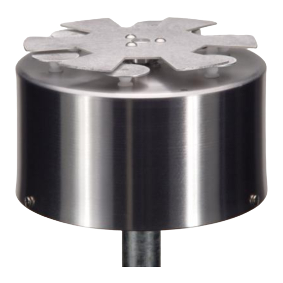
C H A P T E R I N T R O D U C T I O N The EFM-100’s electric field mill senses electric field by repeated exposing and shielding a series of sense electrodes. An electric field mill uses a mechanical chopper to alternately shield and expose several sense plates to an electric field. -
Page 11: Installation
Chapter Installation Connect and test your EFM-100 on the ground before permanently mounting the sensor unit. Install the software on your computer and connect the field mill as shown below. The field mill should respond to charged objects brought near it. Most plastic objects can be easily charged by rubbing them on your clothes. -
Page 12: Efm-100 Display Software Installation
If the setup program does not start automatically you can start it manually by clicking on Start…Run…, type d:setup.exe then click OK. Once the software is installed you can run the EFM-100 display software by clicking on Start…All Programs...Boltek…EFM-100 Electric Field Monitor. -
Page 13: Choosing An Outdoor Mounting Location
Radio Shack store or your local television antenna installer (see Television Antennas in your Yellow Pages). Install the EFM-100 Field Mill on a calm clear day when no thunderstorms are expected. Your local antenna installer can do a safe and professional field mill installation and can also ensure that the field mill is properly grounded. -
Page 14: Figure 5: A Poor Choice Of Mounting Locations
C H A P T E R I N S T A L L A T I O N Mounting the field mill close to tall objects will result low readings as the tall object will shield the field mill sensor. + + + + + + + + + + + + + + + - - - - - - - - - - - - - -... -
Page 15: Epm-1 Power Module
C H A P T E R I N S T A L L A T I O N EPM-1 Power Module The EPM-1 power module is a connection point for sending DC power up to the field mill and connecting to analog signals from the field mill. Figure 7: EPM-1 Power Module Connectors Field Mill Power Cable Connector Connect the black cable from the EPM-1 Power Module’s field mill power connector to... -
Page 16: Analog Output
C H A P T E R I N S T A L L A T I O N Analog Output Analog output is available on the EPM-1 Power Module. Output voltage is 1V per kV/m differential, ranging from +20V corresponding to +20kV/m to -20V corresponding to -20kV/m. -
Page 17: Efa-10 Fiber Optic Adapter
USB if a USB connection is preferred. ST Fiber Optic Connectors The EFM-100 transmits its data over a fiber optic cable. The fiber optic cable uses St style connectors on each end. Figure 11: Female Fiber Optic Connector If the field mill installer is not familiar with ST fiber optic connectors he should familiarize himself with the connectors on the ground, before mounting the field mill on the roof. -
Page 18: Figure 12: Male Fiber Optic Connector
Insert the male connector into the female connector and rotate the locking collar until you feel the tabs stop in the detents. Figure 12: Male Fiber Optic Connector Figure 13: EFM-100 Field Mill Connections... -
Page 19: Figure 14: Sensitivity Plugs
C H A P T E R I N S T A L L A T I O N Power Connector Connect the black cable from the field mill’s power connector to the EPM-1 Power Module’s field mill power connector. The cable supplies 12VDC to the field mill and carries the analog output signals back to the EPM-1. -
Page 20: Calculating A Precise Sensitivity Value
C H A P T E R I N S T A L L A T I O N thunderstorms routinely exceed 20 kV/m (the limit of the field mill) you should change to a lower value Sensitivity Plug (after the storm and when it is safe to do so.) Calculating a Precise Sensitivity Value If you require a precisely calibrated field mill for scientific or other precision applications you will need to calculate a precise correction factor, then order or assemble a custom... -
Page 21: Grounding Detail
Grounding Detail The EFM-100 field mill needs to be grounded for proper operation and for lightning and electrical safety. Connect the connector end of the green ground wire to the field mill ground connector. -
Page 22: Figure 16: Field Mill Grounding Detail
C H A P T E R I N S T A L L A T I O N Figure 16: Field Mill Grounding Detail... -
Page 23: Configuring The Software
Chapter C H A P T E R – C O N F I G U R I N G T H E S O F T W A R E Configuring the Software EFM Options: General Figure 17: EFM Options – General Number of Data Sources Enter the number of field mills for which you would like to display data. - Page 24 C H A P T E R – C O N F I G U R I N G T H E S O F T W A R E Data Source Name Enter a descriptive name for each field mill. If you are displaying the data from more than one field mill the name will be used to identify the source of the data.
-
Page 25: Efm Options: High Field Alarm
C H A P T E R – C O N F I G U R I N G T H E S O F T W A R E EFM Options: High Field Alarm Figure 18: EFM Options – High Field Alarm Field Mill Selector Select the field mill for which you would like to enable or disable High Field Alarm. -
Page 26: Efm Options: Very High Field Alarm
C H A P T E R – C O N F I G U R I N G T H E S O F T W A R E High Field Alarm Duration High Field Alarm Duration is the length of time the High Field Alarm will remain active once the field drops below the alarm setpoint. - Page 27 C H A P T E R – C O N F I G U R I N G T H E S O F T W A R E Field Mill Selector Select the field mill for which you would like to enable or disable Very High Field Alarm. Setpoint Very High Field Alarm Setpoint is the magnitude of electric field required to trigger a Very High Field Alarm.
-
Page 28: Efm Options: Lightning Alarm
C H A P T E R – C O N F I G U R I N G T H E S O F T W A R E EFM Options: Lightning Alarm Figure 20: EFM Options – Lightning Alarm Field Mill Selector Select the field mill for which you would like to enable or disable alarms. -
Page 29: Efm Options: Data Logging
C H A P T E R – C O N F I G U R I N G T H E S O F T W A R E WAV Filenames The WAV Filename is the file which will play out the computer speakers when the On Activation, Distance, Repeat, or All Clear is activated. -
Page 30: Efm Options: Data Sharing
High Resolution Checkbox When the High Resolution box is checked, it will store the EFM-100 data 20 times per second. Leaving it unchecked will store the data 2 times per second. Please note when this option is enabled, it will also increase the file size. - Page 31 Check the Enable Sharing checkbox if you wish to share your field mill data with others. If enabled your EFM-100 software will list on the Listen Port for incoming connections. Once a connection has been made the software will begin transmitting field mill data to the remote computer. There is no limit to the number of concurrent connections.
-
Page 33: Operation
O P E R A T I O N Operation The EFM-100 display software interprets and displays the field mill readings and status. For remote field mills the software also attempts to establish and maintain a network connection with the remote computer’s EFM-100 display software in order to receive the remote data. - Page 34 C H A P T E R O P E R A T I O N Location Descriptor describes the location of the field mill. When the software is configured to display data from multiple field mills the descriptor is important in identifying the source of the data. The History Graph shows the most recent data in graphical form.
-
Page 35: Interpreting The Data Display
C H A P T E R O P E R A T I O N Interpreting the Data Display Often the first indication of an approaching thundercloud is a positive field reading followed by a field reversal to a negative field as the cloud moves overhead. Figure 24: Approaching Thundercloud Figure 25: Increasing Field due to Approaching Thundercloud... -
Page 36: Figure 26: Thundercloud Directly Overhead
C H A P T E R O P E R A T I O N Figure 26: Thundercloud Directly Overhead Figure 27: Electric Field Polarity Reversal With the thundercloud directly overhead the polarity of the field has reversed to a negative electric field. -
Page 37: Figure 28: Departing Thundercloud
C H A P T E R O P E R A T I O N Figure 28: Departing Thundercloud Figure 29: End of Storm Oscillation Once the cloud has passed over the field will often reverse back to positive before decaying to a normal fair-weather electric field reading of about 0.1 kV/m. -
Page 38: Figure 30: Step Changes In Field Magnitude Indicate Lightning
Figure 30: Step Changes in Field Magnitude Indicate Lightning Step changes in the magnitude of the electric field indicate lightning. Closer lightning produces larger field changes than distant lightning. The EFM-100 can detect lightning out to about 30 miles. Figure 31: Precipitation Noise Rain, snow, and dust can carry an electric charge. -
Page 39: Maintenance
M A I N T E N A N C E Maintenance Your EFM-100 should run for years with very little maintenance. An occasional cleaning may be all that is necessary. In most installations even that will not be necessary as rain will wash away any accumulated dirt. -
Page 41: Troubleshooting
Signal Lost Fault Solution: The EFM-100 software will report a “signal lost” fault if it does not receive data from the field mill for more than a few seconds. You will need to determine why the data is not reaching the software. - Page 42 If the rotor is found to be spinning either too fast or too slow the supervisory circuitry will change the fault status in the data stream from a 0 (no fault) to a 1 (rotor fault.) The EFM-100 display software will indicate a Rotor Fault.
-
Page 43: Efm-100 Data Format
Appendix EFM-100 Data Format The EFM-100 Electric Field Mill transmits data sentences down the fiber optic cable at the rate of ten readings per second. The EFA-10 converts the optical signal to standard RS232 at 9600 baud, 8 data bits, no parity, 1 stop bit. -
Page 45: Specifications
A P P E N D I X – S P E C I F I C A T I O N S Appendix Specifications EFM-100 Hardware Specifications Electric Field Range: -20 kV/m to +20 kV/m Typical Range of Interest: -5 kV/m to +5 kV/m Response Time: 0.1 seconds... - Page 46 S P E C I F I C A T I O N S Shipping Dimensions: 18.5" x 13" x 8.8" (47 x 33 x 22 cm) Warranty: 1 Year EFM-100 Software Specifications Operating System: Microsoft Windows XP, 2000, NT, 98, 95 Alarms: High Field Alarm, Very High Field Alarm, Lightning Alarm...
Need help?
Do you have a question about the EFM-100 and is the answer not in the manual?
Questions and answers
From the output data of EFM-100C, we get 3 coloumn, the first coloumn is time, what is the meaning of the second and the third column? and, please tell me the meaning of positive and negative data output of EFM-100C. with the extention is .efm
The second column in the output data of the Boltek EFM-100C represents electric field strength in volts per meter (V/m), and the third column represents the temperature inside the EFM-100 housing in degrees Celsius (°C). A positive data output in the .efm file indicates a downward electric field (positive charge overhead), while a negative output indicates an upward electric field (negative charge overhead).
This answer is automatically generated