
Summary of Contents for SUMAVISION TECHNOLOGIES EMR3B
- Page 1 SUMAVISION Operating Instructions Integrated Media Processing Platform Enhanced Multimedia Router SUMAVISION TECHNOLOGIES CO., LTD.
- Page 2 Version Description Sumavision Technologies Co., Ltd. Copyright and all rights reserved. Without paper permission of Sumavision Technologies Co., Ltd, any company or individuals are not allowed to extract, copy part or all of this book, and spread in any form.
- Page 3 Digital video/audio system engineers Contact Us Sumavision Technologies Co., Ltd. is committed to providing a full range of technical support. When users are not familiar with the device or any fault of the device occurs, it is recommended not to disassemble the device, but to contact Sumavision Office or the After-sales Technical Support Department of the Company.
-
Page 4: Table Of Contents
SUMAVISION EMR Operation Introduction Content SUMAVISION ............................1 OPERATING INSTRUCTIONS ......................1 CHAPTER 1 OVERVIEW ......................1 ........................ 1 ETWORK OLUTION ..................1 ERFORMANCE ARAMETERS ......................2 PPLICABLE TANDARDS CHAPTER 2 PRODUCT DESCRIPTIONS .................. 3 ......................3 RODUCT DENTIFICATION ..........................3 PPEARANCE 2.2.1 Indicator .......................... - Page 5 SUMAVISION EMR Operation Introduction ........................43 UTPUT ETTINGS CHAPTER 7 FAULT ANALYSIS AND TROUBLESHOOTING ..........44 ......................44 LARM NFORMATION 7.1.1 LCD does not display after powering on ................44 7.1.2 ASI 5-channel input card fails to refresh any input signals..........45 7.1.3 ASI 4-channel output card fails to output the decoding normally ........
-
Page 6: Sumavision
SUMAVISION EMR Operation Introduction Chapter 1 Overview SUMAVISION Enhanced Multimedia Route, which can be abbreviated to EMR, is a new generation multi-media exchange platform. This device, which uses 1U card plug-in structure, and supports at most 6 boards (cards) as well as dual-power redundancy backup. -
Page 7: Applicable Standards
SUMAVISION EMR Operation Introduction Support the encoding of HD and SD video resolutions Audio encoding: Dolby AC3 and MPEG-1 Layer II Support DS3, ATM and other adaption format Support Gigabit Ethernet input/output Support multi-channel ASI output ... -
Page 8: Chapter 2 Product Descriptions
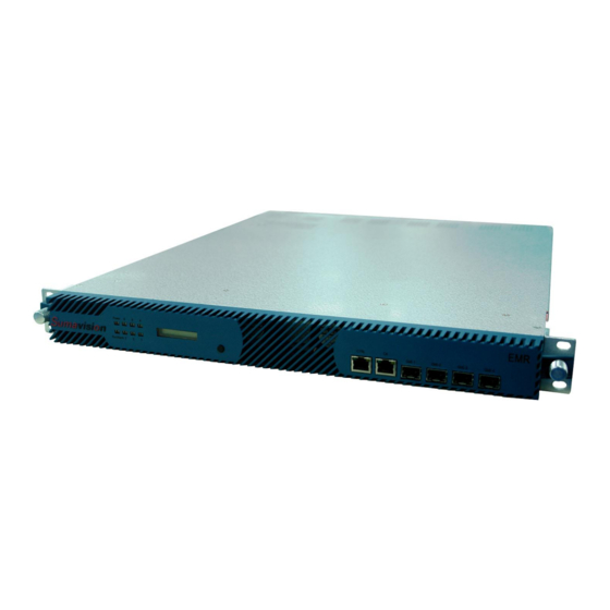
Fig. 2-2 Ex-factory Identification. EMR3B081006 Fig. 2-4 Ex-factory Identification Where, “S/N” refers to the ex-factory serial number, “EMR3B” stands for the device model and “081006” is the production code. 2.2 Appearance EMR appearance is shown as Fig. 2-3 EMR Appearance. -
Page 9: Lcd
SUMAVISION EMR Operation Introduction Run/Alarm Operating indicators (1-6) Connect to the power supply and turn on the power switch, the indicator of Power keep lighting. When the device starts and operates normally, there is no abnormalty, the indicator of Run/Alarm on the device panel will turn green. -
Page 10: Keyboard Operating
SUMAVISION EMR Operation Introduction LCD button to display IP and subnet mask information of the device, press and hold the LCD button to display current alarm information of the device. 2.2.3 Keyboard Operating User can enable the LCD panel through keyboard to view the IP of the device. 2.2.4 Connector of the Device SUMAVISION EMR rear panel adopts the form of sub-panels. -
Page 11: Interface Performance
SUMAVISION EMR Operation Introduction 2.2.5 Interface Performance 2.2.5.1 ASI 5-input card ASI 5-input card provides 5-channel 75ΩBNC interface for ASI signal input, as shown in Fig. 2-6 ASI 5-input card: Fig. 2-7 ASI 5-input card 2.2.5.2 ASI 4-Output Scrambling Card ASI 4-Output Scrambling Card provides 4-channel 75ΩBNC interface for ASI signal output, and an Ethernet interface for CAS connection, as shown in Fig. -
Page 12: Analog Sd Mpeg2 Encoding
SUMAVISION EMR Operation Introduction 2.2.5.5 Analog SD MPEG2 Encoding Card Analog SD MPEG2 Encoding Card provides the video input interface of 75ΩBNC, and provides audio input interface as the phoenix printed circuit board terminals of MINI COMBICON (MC) socket and plug, plug direction parallel with conductors axial. Analog SD MPEG2 Encoding Card is shown in Fig. -
Page 13: Heat Emission Descriptions
SUMAVISION EMR Operation Introduction Fig. 2-12 4-frequency DVB-S2 Demodulation Receiving Card 2.2.5.8 Power socket EMR provides two power sockets on the rear panel. The device will be powered on if the power lead is insert the power socket correctly. The power sockets used by EMR fully conform to the international industrial standards, for detailed information, refer to Table 10-3 Power Socket Parameters. -
Page 14: Chapter 3 Safety Precautions
SUMAVISION EMR Operation Introduction Chapter 3 Safety Precautions 3.1 Outline Dimensions EMR external structure is shown as Table 3-1 EMR Physical Parameters. Table 3-1 EMR Physical Parameters Physical Parameters Value (Unit) Height 44.4mm (1U) Width 482.6mm (19") Depth 564.7mm 3.2 Weight The device weights <7.5kg, and its specific quality is related to the configurations of the device. - Page 15 SUMAVISION EMR Operation Introduction the door or routine maintenance. The cabinet can not be installed against the wall, and the distance between the cabinet side and the wall should be not less than 0.8m. Site room floor: Site room floor should be non-conductive, dust-proof, and its surface smoothness error should be less than 2mm per square meter.
-
Page 16: Power Supply Requirement
SUMAVISION EMR Operation Introduction system or fixed extinguishing system. Power supply requirements: The devices, air-conditioning system and lighting system should have their own power system respectively. 3.3.3 Power supply Requirement Parameters for normal operation of EMR are shown as follows: ... -
Page 17: Chapter 4 Installation And Debugging
SUMAVISION EMR Operation Introduction Chapter 4 Installation and Debugging 4.1 Unpacking and Checking Please check whether the package of the device is damaged or not when receiving the device; in case of device’s damage, please contact the carrier company or the After-sales Technical Support Department of Sumavision in a timely manner. -
Page 18: Debugging
SUMAVISION EMR Operation Introduction Fig. 4-2 Assembly cabinet for EMR ====================================== The device can be installed in any plug-in frame of the assembly cabinet. However, the general principle for arranging the location of the device is that the connection between various stand-alone devices should be arranged neatly on the assembly cabinet in accordance with the flow of signal. -
Page 19: Methods For Debugging And Testing
SUMAVISION EMR Operation Introduction 4.5 Methods for Debugging and Testing EMR provides the function of Device IP address search through LCD display. The button can be used to light the LCD normally to facilitate the use by users. 4.6 Device Upgrade Step 1: View device IP through the LCD panel. - Page 20 SUMAVISION EMR Operation Introduction The device will restart automatically after completing the upgrade. 15 /53...
-
Page 21: Chapter 5 Operating Methods
SUMAVISION EMR Operation Introduction Chapter 5 Operating Methods This chapter mainly introduces the methods for system setting and use of EMR, which may be helpful for users to know initial knowledge about the system setting and operation steps of EMR. The system setting includes device IP, user management, factory reset and restart;... -
Page 22: System Setting
SUMAVISION EMR Operation Introduction Fig. 5-1 EMR WEB Network Management Screen 5.1.1 System Setting The System Setting menu includes the following four sub-menu: System parameter: search EMR version information, set the IP address, gateway address and subnet mask, then click “Submit” button to complete the setting;... - Page 23 SUMAVISION EMR Operation Introduction User Management: you can add/delete users, the user types including system administrator and ordinary user. Factory reset: after using this function, EMR will restart automatically, and all parameters except the device IP will be resorted to the factory settings. Does not recommend to use.
-
Page 24: Operating Method
SUMAVISION EMR Operation Introduction Restart: It means that soft reboot the EMR. 5.1.2 Operating Method EMR is the core head-end access device of digital TV. By configuring different board cards, 19 /53... - Page 25 SUMAVISION EMR Operation Introduction users can finish encoding, decoding, QPSK demodulation, DVB-S2 demodulation and descrambling, QAM demodulation and descrambling, DS3 adaptive input/output, QAM modulation output, ASI multiplexing and routing, IP multiplexing and routing, TS and IP signal scrambling, etc. To complete the configuration of device successfully, we’ll describe basic operating processes of EMR through three parts: input section, multiplexing section and output interface section.
- Page 26 SUMAVISION EMR Operation Introduction Fig. 5-1 Multiplexing Screen of WEB Network Management Step 1: Click “Multiplexing Setting” on the network management screen to navigate to the multiplexing screen; Step 2: Select an input board card; Step 3: Select a program to be multiplexed; Step 4: Select an output board card for multiplexing;...
-
Page 27: Board Card Description
SUMAVISION EMR Operation Introduction RF output: Insert a 6-adjacent-channel QAM modulation card (Refer to 6-adjacent-channel QAM modulation card) into the platform to provide RF output for the platform. 5.2 Board Card Description This section will introduce the board cards applied in EMR to help users understand the version information, status information and parameter settings of each kind of board card. - Page 28 SUMAVISION EMR Operation Introduction WEB Network Management Screen There are the following seven sub-menu: Status information: search the version information, status information, input/output information of the board card; Board card parameter setting: Set the parameters for Ethernet port 1 and 2, including IP address, subnet mask, gateway, speed and duplex, optical output amplitude;...
- Page 29 SUMAVISION EMR Operation Introduction added receiving port, and includes such functions as Add, Delete, Delete All and Modify in Batch. After finishing the modification, click “Submit” to make the modifications take into effect. Add Port: This screen is used to add ports and set the parameters of the added ports. Web Network Management Screen Parameter Range...
- Page 30 SUMAVISION EMR Operation Introduction the IANA reserved address unavailable) Source IP2 1.1.1.1~223.254.254.254 Complete according to the actual situations. (127.0.0.0~127.255.255.255, the IANA reserved address unavailable) Baseline switch On/Off Baseline bit rate 0-300000000 Specified PID 1~1FFF 1FFF Alarm switch On/Off Delete: Delete the selected port; Delete All: Delete all added ports;...
- Page 31 SUMAVISION EMR Operation Introduction Parameter Range Recommended value Receiving IP 1.1.1.1~223.254.254.254 Complete according to the actual situations. (127.0.0.0~127.255.255.255, the IANA reserved address unavailable) Receiving port 1~65535 Complete according to the actual situations. Receiving mode INCLUDE/EXCLUDE EXCLUDE Source IP1 1.1.1.1~223.254.254.254 Complete according to the actual situations.
- Page 32 SUMAVISION EMR Operation Introduction Web Network Management Screen Parameter Range Recommended value Complete according to the Number of port added 1~256 actual situations. System bit rate 0~1000000000 30000000 Output packet length 188/204 Complete according to the Destination IP Unicast IP or multicast IP actual situations.
- Page 33 SUMAVISION EMR Operation Introduction Delete All: Delete all added ports; Modify in batch: Select several ports to select and modify specific parameters; Web Network Management Screen Parameter Range Recommended value System bit rate 0~1000000000 30000000 Output packet length 188/204 Complete according to the Destination IP Unicast IP or multicast IP actual situations.
-
Page 34: Asi 5-Channel Input Card
SUMAVISION EMR Operation Introduction 5.2.2 ASI 5-channel Input Card ASI 5-channel input card supports 5-channel ASI input, and can search current version information, status information and parameter settings of ASI 5-channel input card through WEB Network Management System. Web Network Management Screen Parameter Range Recommended value... -
Page 35: 6-Adjacent-Channel Qam Modulation Card
SUMAVISION EMR Operation Introduction card, as shown in the following figure: WEB Network Management Screen Parameter Range Recommended value System output 0~213000000 30000000 bit rate Output packet 188/204 length Regenerated On/Off Alarm switch On/Off 5.2.4 6-adjacent-channel QAM Modulation Card 6-adjacent-channel QAM modulation card is equipped with a RF output interface supporting 6-adjacent frequency output. - Page 36 SUMAVISION EMR Operation Introduction parameter settings of 6-adjacent-channel QAM modulation card, as shown in the following figure: WEB Network Management Screen Parameter Range Recommended value Channel ANNEX_A/B Set according to encoding mode the needs Channel 6/8M Set according to bandwidth the channel encoding mode Authorization...
-
Page 37: 4-Frequency Dvb-T2 Demodulation Receiving Card
SUMAVISION EMR Operation Introduction 5.2.5 4-frequency DVB-T2 Demodulation Receiving Card 4-frequency DVB-T2 Demodulation Receiving Card provides 4 RF input interfaces, for DVB-T/T2 standard RF signal reception. The WEB Network Management System can be used to search the current status information and set receiving parameters of 4-frequency DVB-T2 Demodulation Receiving Card, as shown in the following figure: WEB Network Management Screen 5.2.6 Analog SD MPEG2 Encoding Card... -
Page 38: Hd 422 Decoding Card
SUMAVISION EMR Operation Introduction WEB Network Management Screen 5.2.7 HD 422 Decoding Card HD 422 Decoding Card can decode SD or HD program, supporting the outputs of 1 video and 2 audios (hardware version V3.2 supports 4 audio outputs). The program needed to be decoded can be selected by multiplexing function. -
Page 39: 4-Frequency Dvb-S2 Demodulation Receiving Card
SUMAVISION EMR Operation Introduction WEB Network Management Screen 5.2.8 4-frequency DVB-S2 Demodulation Receiving Card 4-frequency DVB-S2 Demodulation Receiving Card provides 4 RF input interfaces, for DVB-S/S2 standard RF signal reception. The WEB Network Management System can be used to search the current status information and set receiving parameters of 4-frequency DVB-S2 Demodulation Receiving Card, as shown in the following figure: 34 /53... -
Page 40: Web Network Management For Scrambling Module
SUMAVISION EMR Operation Introduction WEB Network Management Screen 5.3 Web Network Management for Scrambling Module In EMR, the Scrambling module uses CA network interface, and can be set independently by web network management. The first time setting scrambling module in EMR, we need to query the IP address, which can be checked from the web network management. -
Page 41: System Setting
SUMAVISION EMR Operation Introduction Fig. 5-3 EMR3.0 Web NMS for Scrambling Module 5.3.1 System Setting There are four submenus in the system setting menu. System parameters: in which we can set IP address, subnet mask and gateway, set authorization information, and set PID’s display. Click button “Submit”... - Page 42 SUMAVISION EMR Operation Introduction Fig. 5-5 User Information for Scrambling Web Status information: there are three sub pages: system status, ECM status and EMM status. System status shows the version information of the system, EMM’s total bit rate and EMM’s memory used percent,Fig. 5-; ECM status shows the connect status of ECM, as shows in Fig.
- Page 43 SUMAVISION EMR Operation Introduction Fig. 5-7 ECM Status Fig. 5-8 EMM Status Device restart: this function is for the scrambling module in EMR to restart itself,Fig. 5-. 38 /53...
-
Page 44: Program Scramble
SUMAVISION EMR Operation Introduction Fig. 5-9 Restart Page 5.3.2 Program Scramble The web page for Program Scramble is displayed in Fig.Fig. 5-. Fig. 5-10 Program Scramble Web Page There are three parts in the program scramble page: port select, scramble set and scamble option. -
Page 45: Port Setting
SUMAVISION EMR Operation Introduction After the port is setting ok or the table is searched, if the port, CAS, EMM is already setting ok, then we only need to do the scramble setting job. For the single PID scrambling, we need to select the checkbox before the “Program list”... -
Page 46: Cas Setting
SUMAVISION EMR Operation Introduction 5.3.4 CAS Setting CAS setting page is shown below in Fig. 5-12. Fig. 5-12 CAS Setting First, select group, and set the CAS parameters for the group. Key period’s value deponds on the customer’s requirement, other parameters are supplied by CAS, and the parameters just need to match the CAS server. - Page 47 SUMAVISION EMR Operation Introduction Fig. 5-13 EMM Setting For all the contents in this page please under the guide of CAS setting. 42 /53...
-
Page 48: Chapter 6 Descriptions Of Advanced
SUMAVISION EMR Operation Introduction Chapter 6 Descriptions of Advanced 6.1 Output Settings This screen can add the corresponding pass-through relationship by applying the function of set-port mapping, and then the output port can directly output the input stream of corresponding port. Step 1: Set the output mode of corresponding output port as pass-through;... -
Page 49: Chapter 7 Fault Analysis And Troubleshooting
SUMAVISION EMR Operation Introduction Chapter 7 Fault Analysis and Troubleshooting 7.1 Alarm Information When EMR runs abnormally, the alarm indicator on the front panel of the device will light, and the Web network management will provide a variety of abnormality alarm to prompt the users to facilitate the investigation and solve the problems. -
Page 50: Asi 5-Channel Input Card Fails To Refresh Any Input Signals
SUMAVISION EMR Operation Introduction Solution: EMR can be allowed to leave the factory only if the test ensures that all function indicators meet the requirements. Therefore it is almost unlikely that the LCD module of the device is broken, thus this cause can be excluded; check the power lead of the device to confirm whether there’s any damage to the surface of the power lead, check the quality of power socket to confirm whether the supply voltage is normal. -
Page 51: 6-Adjacent-Frequncy Qam Modulation Card Output Can't Be Received By Stb
SUMAVISION EMR Operation Introduction rate for output programs. 7.1.4 6-adjacent-frequncy QAM modulation card output can’t be received by STB. Reasons for such fault: The output level of 6-adjacent-frequency QAM modulation card is too high; Wrong receiving parameters of the STB are set. Solution: Lower the output level of 6-adjacent-frequency QAM modulation card to be in the range that STB can receive the output;... -
Page 52: Chapter 8 Maintenance
The device is inspected according to the specifications & instruction manual of Sumavision Technologies Co., Ltd. The man-made accident should be prevented. Wear the anti-static bangle when operating the device hardware. -
Page 53: Routine Maintenance
Don’t reset the device easily and change the service data. For any alarm with unidentified reasons, please contact the After-sales Technical Support Department of Sumavision Technologies Co., Ltd. 8.3 Routine maintenance Refer to Table 8-1 for routine maintenance. Table 8-1... -
Page 54: Quarterly Maintenance
SUMAVISION EMR Operation Introduction Table 8-2 M maintenance onthly Maintenance Maintenance contents Operation guide Reference standard Reference type maintenance hour (man×hour) Check Cabinet cooling hole Check the state of Keep clean around the cooling external state cooling holes. holes, without any mess. environment 8.5 Quarterly Maintenance Refer to Table 8-3 for quarterly maintenance. -
Page 55: Operation And Maintenance
SUMAVISION EMR Operation Introduction be penetrated into the device. Do not plug in and out all connection cables with current without instructions. Check whether the cable is pressed or pulled by the heavy object, whether the plug and socket are connected tightly, ensure that the cable is not extruded by the external force and is placed in order. -
Page 56: Annex A
SUMAVISION EMR Operation Introduction Annex A Table 8-5 Parameters of input/output interface 75Ω Electrical Normal appearances characteristics impedance can be shown as the figure below: Frequency range 0-2GHz Voltage rating 500 VRMS (Sea-level Max.) Dielectric 1500 VRMS (Sea-level Min.) withstand voltage VSWR 1.5 (Max)
Need help?
Do you have a question about the EMR3B and is the answer not in the manual?
Questions and answers