Table of Contents
Advertisement
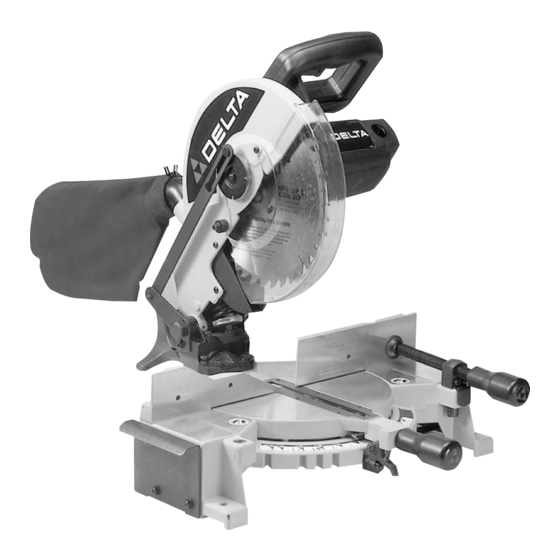
10" Compound Miter Saw
(Model 36-225)
PART NO. 899935 - 03-14-02
Copyright © 2002 Delta Machinery
To learn more about DELTA MACHINERY
ESPAÑOL: PÁGINA 21
visit our website at: www.deltamachinery.com.
For Parts, Service, Warranty or other Assistance,
1-800-223-7278 (
1-800-463-3582).
please call
In Canada call
Advertisement
Table of Contents

Related Manuals for Delta 36-225


Summary of Contents for Delta 36-225
- Page 1 10" Compound Miter Saw (Model 36-225) PART NO. 899935 - 03-14-02 Copyright © 2002 Delta Machinery To learn more about DELTA MACHINERY ESPAÑOL: PÁGINA 21 visit our website at: www.deltamachinery.com. For Parts, Service, Warranty or other Assistance, 1-800-223-7278 ( 1-800-463-3582).
-
Page 2: General Safety Rules
GENERAL SAFETY RULES Woodworking can be dangerous if safe and proper operating procedures are not followed. As with all machinery, there are certain hazards involved with the operation of the product. Using the machine with respect and caution will con- siderably lessen the possibility of personal injury. -
Page 3: Additional Safety Rules For Miter Saws
1. USE ONLY CROSS-CUTTING SAW BLADES. WHEN USING CARBIDE TIPPED BLADES, MAKE SURE THEY HAVE A NEGATIVE HOOK ANGLE. 2. DO NOT OPERATE the miter saw until it is com- pletely assembled and installed according to the instruc- tions. 3. IF YOU ARE NOT thoroughly familiar with the oper- ation of compound miter saws, obtain advice from your supervisor, instructor or other qualified person. -
Page 4: Motor Specifications
A separate electrical circuit should be used for your machines. This circuit should not be less than #12 wire and should be protected with a time lag fuse. If an extension cord is used, use only 3-wire extension cords which have 3-prong grounding type plugs and matching receptacle which will accept the machine’s plug. -
Page 5: Extension Cords
FOREWORD Delta Model 36-225 is a 10" compound miter saw designed to cut wood or aluminum extrusion. Compound angle and bevel cutting are easy and accurate. It can crosscut up to 5-5/8" x 2-3/4", miter at 45° both left and right 4" x 2-3/4", bevel at 45°... -
Page 6: Assembling Table Extensions
4 - Clamp 5 - Table Extension (2) ASSEMBLY INSTRUCTIONS WARNING: FOR YOUR OWN SAFETY, DO NOT CONNECT THE MITER SAW TO THE POWER SOURCE UNTIL THE MACHINE IS COMPLETELY ASSEMBLED AND YOU HAVE READ AND UNDERSTOOD THE ENTIRE OWNER’S MANUAL. -
Page 7: Assembling Dust Bag
ASSEMBLING WORK CLAMP 1. The work clamp (A) Fig. 7, can be used on either the right or left side of the saw base. Insert post of work clamp (A) into the hole located on either the right or left side of the saw base. -
Page 8: Fastening Machine To Supporting Surface
Before operating your compound miter saw, make sure it is firmly mounted to a sturdy workbench or other supporting surface. Four holes are provided, two of which are shown at (A) Fig. 9, for fastening the saw to a supporting surface. -
Page 9: Operating Controls
(B) Fig. 14 with vent unauthorized use, a 3/16" diameter shackle. ROTATING TABLE FOR MITER CUTTING Your miter saw will cut any angle from a straight 90 on scale) cut to 47 ° right and left. Simply loosen lock han- dle (A) Fig. -
Page 10: Pointer And Scale
1°. In effect, when the pointer is moved from one line to the next on the scale, the angle of cut is changed by 1°. TILTING CUTTINGHEAD FOR BEVEL CUTTING The cuttinghead of your compound miter saw can be tilted to cut any bevel angle from a 90 a 45 °... -
Page 11: Rear Support/ Carrying Handle
CARRYING HANDLE A rear support bar (A) Fig. 19, is provided to prevent the miter saw from tipping to the rear when the cuttinghead is returned to the raised position after a cut has been made. For maximum support, support bar (A) should be pulled out as far as possible before attempting to per- form a cut. -
Page 12: Adjusting Table Positive Stops
(H), and make the required adjustments. Then tighten fence mounting screws. NOTE: Make certain the saw is still cutting a true 90°. 2. Move the table to the 0 ° straight cut-off position, making sure the plunger (B) is engaged in the 0 °... - Page 13 TRAVEL OF SAW BLADE 1. DISCONNECT THE SAW FROM THE POWER SOURCE. 2. The downward travel of the saw blade can be limit- ed to prevent the saw blade from contacting any metal surfaces of the machine. This adjustment is made by loosening locknut (A) Fig.
-
Page 14: Adjusting Blade Parallel To Table Slot
PARALLEL TO TABLE SLOT 1. DISCONNECT THE SAW FROM THE POWER SOURCE. 2. Lower the cutting arm. The saw blade (A) Fig. 33, should be parallel to the left edge (B) of the table open- ing. 3. If an adjustment is necessary, raise the cuttinghead, loosen screws (C) Fig. -
Page 15: Auxiliary Wood Fence
When performing multiple or repetitive cut-off operations that result in small cut-off pieces, one inch or less, it is pos- sible for the saw blade to catch the cut-off pieces and project them out of the machine or into the blade guard and housing, possibly causing damage or injury. -
Page 16: Cutting Aluminum
When cutting aluminum extrusions, or other sections that can be cut with a saw blade and are within the capacity of the machine, position the material so the blade is cutting through the smallest cross- section, as shown in Fig. -
Page 17: Cutting Crown Moulding
CUTTING CROWN MOULDING One of the many features of your saw is the ease of cut- ting crown moulding. The following is an example of cut- ting both inside and outside corners on 52/38° wall angle crown moulding. NOTE: When cutting 45° wall... -
Page 18: Constructing Work Support Extensions
3-1/2 inches. This enables you to fasten standard 2 x 4’s (C) to the top of the 2 x 4’s (A), as shown. The top of the 2 x 4’s (C) will then be the same height as the miter saw table. This method allows you to provide support for long work-pieces using standard 2 x 4’s instead of constructing an expensive, complicated work support. -
Page 19: Brush Inspection And Replacement
Fig. 50, making sure flats on outside blade flange are engaged with flats on arbor shaft. 6. Thread arbor screw (C) Fig. 50, into saw arbor by turning screw (C) counterclockwise as far as possible by hand. Then tighten arbor screw (C) with wrench supplied while at the same time pressing in on arbor lock (D) Fig. -
Page 20: Parts, Service Or Warranty Assistance
A complete line of accessories is available from your Delta Supplier, Porter-Cable • Delta Factory Service Centers, and Delta Authorized Service Stations. Please visit our Web Site for the name of your nearest supplier. WARNING: Since accessories other than those offered by Delta have not been tested with this product, use of such accessories could be hazardous. - Page 21 Parts and accessories for Porter-Cable ·Delta products should be obtained by contacting any Porter-Cable·Delta Distributor, Authorized Service Center, or Porter-Cable·Delta Factory Service Center. If you do not have access to any of these, call 800-223-7278 and you will be directed to the nearest Porter-Cable·Delta Factory Service Center. Las Estaciones de Servicio Autorizadas están ubicadas en muchas grandes ciudades.