Advertisement
Advertisement

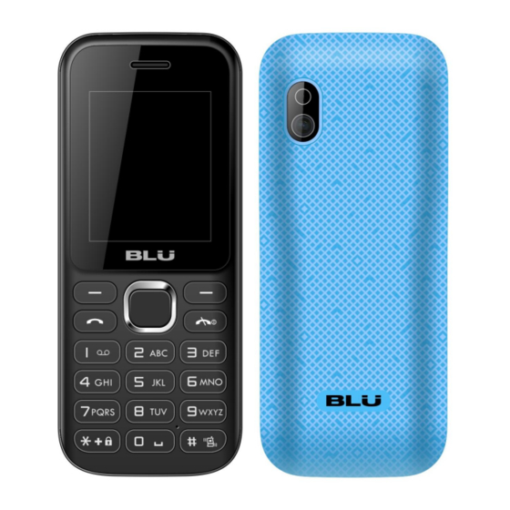
Related Manuals for Blu ARIA II


Summary of Contents for Blu ARIA II
- Page 1 ARIA II SERVICE MANUAL...
-
Page 2: Table Of Contents
CAUTIONS 1、 Please read this service manual carefully and make sure all elements of anti-static are in place before the repair work is carried out. 2、 Servicing and alignment MUST be undertaken by qualified personnel only. 3、 Please use specified tools and equipments for servicing, in which the parameters need to be calibrated with specified criteria. - Page 4 Aria II Features & Functions Dual SIM MT 6260M 24Mb+32Mb Fashion bar phone Moner detector flash Multi-Media application 0.08M sw upgarde to 0.3M by sw T-Flash(Support 8G T Card) 1.8“TFT 128*160 ...
-
Page 5: Exploded View
Chapter 2 Exploded View 1. Lens 3. Receiver 4. Front cover 5. FM antenna 7. LCD 9. PCBA 11. Speaker 13 Back cover 18 Battery 19 Camera 21 DOME 22 Keypad... -
Page 6: Tools
Chapter 3 Tools Solder iron Hot Air Gun Power Supply Multimeter Solder wire, Flux Tweezer Screw Cable Driver Wrist grounding strap Antistatic gloves Pick PC, Download cable Others... -
Page 7: Assembly
Chapter 4 Disassembly & Assembly 1. Disassembly Process 1. Remove the battery cover 2. Unfasten the 4 screws by screw driver 3. Prize up the back cover by pick 4. Remove the PCBA .. 5. Stick protection film for front cover. 6. - Page 8 7. Remove the FM antenna by iron 8. Remove the speaker by iron 10. Remove the camera by iron 9. Remove the LCD by iron 11. Remove the keying film Finished.
- Page 9 2. Assembly Process 2. Install the camera. 1. Install the keying film 4. Install the speaker by iron. 3. Install the LCD by iron.. 5. Install the FM antenna by iron.. 6. Remove the protection film front cover...
- Page 10 6. Install the PCBA. 6. Remove the protection film LCD 6. . Install the back cover 6. Fasten the screws 6.. Install the battery cover Finished.
- Page 11 Chapter 5 Picture of PCBA 5.1 Side A Side A Keypad PCBA (Side A) Location of components LCD connector Connector Camera (J701) connector(J702) 5.2 Side B Side B PCBA (Side B) Location of Components SIM connector T-flash connector 26Mhz Light (J403) (J404) (U301)
-
Page 12: A&B Of Pcba Layout
5.3 PCBA Layout side A 5.4 PCB Layout Side B... -
Page 13: System Block Chart
Chapter 6 System Block Chart... - Page 14 Chapter 7 Unit Circuit 7.1.1 System Overview MT6260M is a monolithic chip integrating leading edge power management unit, analog baseband and radio circuitry based on the low power CMOS process. MT6260M is a feature-rich and extremely powerful single-chip solution for high-end GSM/GPRS and EDGE-Rx capability.
- Page 15 Chapter 7 Unit Circuit 7.1.2 Baseband & CPU Audio Processing Keypad Interface SIM Data Transfer control Data Transfer Interface T- T-flash Data transfer control...
- Page 16 7.1.3 Keypad Input Interface 7.1.4 Output of SIM Card...
- Page 17 7.1.5 Display interface circuit Read/write control signal Led control signal Display control bus...
- Page 18 The battery test Input battery...
- Page 19 Power amplifier 7.1.6 Start signal Power supply input Radio frequency signal input Received signal output...
- Page 20 System Overview The AP5200 is a dual-band frond-end module for GSM900 and DCS1800 operation. It offers complete handset transmitting receiving function including, transmitting transceiver-to-antenna and receiving antenna-to-SAW filter, in a compact module. It also supports GPRS Class 12 multi-slot operation.
- Page 21 7.1.7 I/O Interface (5PIN) Charging voltage input Sofware download port The data transfer...
-
Page 22: Trouble Shooting Guide
Chapter 8 Trouble shooting guide Can’t Download Cannot download Check if it is caused by the Power on PC, cable, tools etc. Replace or re-config. Replace or Check I/O Connector re-solder the I/O connector Connect the cable, check if Disconnect the cable the current is normal (about and check if the chipset 30 mA) - Page 23 Cannot power on-current swing instability Make the phone connect the power supply and find the current swing at 50-100mA Upgrade the software Check and replace the I/O connector Check the power manage supply output: VCCRE 1.8V VDD 2.8V AVDD 2.8V Replace or VTCXO 2.8V reweld CPU...
- Page 24 Cannot power on-low or no current Make the phone connect the power supply and find low or no current , Check battery Clean connector and power reweld replace it Upgrade the software Check and replace I/O Check the power manage connector supply output:...
- Page 25 Cannot Power on-large current Make the phone connect the power supply and then press power key find large current make the phone heat Check if the phone leakage (current 0mA is normal) Use the Check and touch replace RF method to PA, Audio Check if the capacitance, varistor, LDO tube leakage...
- Page 26 Repair flow for phone dead Phone dead Upgrade the software can Upgrade the settle the defect issue? Software. Check battery connector Clean or replace the battery and battery touch point if or battery connector. is dropped or dirty? Check the keypad if stuck or Check and reinstall the keypad touch panel do not work to or replace the touch panel.
- Page 27 No display or display abnormality No display or display abnormality after power on Check LCD if damage or Change LCD liquid flow out Check LCD connector Clean/re-solder is OK or not connector Change LCD FPC Problem solve Check if 13 PIN of J701 have signal Upgrade software or not, check 8...
- Page 28 Test process for Key can’t work Key can’t work Single key can’t All key can’t Some of key can’t work work work (e.g: 1/2/3, regular problem) Clean it Upgrade software Use multimeter to check if to check if can the voltage is 0.7V or not solve this problem Visual check if any corrosion or short Clean the place...
- Page 29 Key light can’t work Key light can’t work Reassemble FPC Expect bar model Use multimeter to check Check if circuit is voltage of LED is OK or not broken Upgrade software Problem solve 软件升级 Use external power (2.8V) to Change LED check LED can work or not Changed or re-solder CPU MT6260 Problem solve...
- Page 30 Insert SIM Repair Process Insert SIM Clean or replace Check if all the SIM connector. SIM pins are clean Resolved If SIM card Replace SIM card is available CPU MT6260 Connect Power supply may be defective to check the current MT6260 may be defective Resolder or replace...
- Page 31 N0/weak signal trouble shooing No or weak signal Inspect the antenna and Replace the defective antenna connector to see components. if there’s any distortion Put a false antenna at RF PA Replace RF PA IC. IC to see if there’s any signal Make a false antenna at Saw filter is damaged, J501, check if there’s any...
- Page 32 No/Low sound from Speaker No sound or noise Remove the speaker and Press power on and side button to measure with multimeter to check if there’s the ring is normal see if there’s any sound. Set the phone as The phone is in Replace speaker.
- Page 33 Receiver low voice or no voice Receiver is low. Set the phone as Check if LS401 hands-free mode is damaged. Re-weld clean LS401 Check if the receiver Replace the is broken or damaged receiver. Test if there’s sound from Replace receiver receiver with multimeter Measure the signal with oscillograph...
- Page 34 No/Low sound from MIC No/Low sound from MIC Check if there’s Install the MIC cover MIC cover *#84666*# and activate echo loop, measure MIC MK400 Replace MIC voltage is 1.5V、0.7V Check if inductor R505、 Replace R505 or R506 R506 is damaged. Measure C526/C527 with Replace multimeter to see if there’s...
- Page 35 Does not charge – remind error charge Remind error during charge Remind: “fault connection” “battery overheat” Change battery Re-flash SW Check battery connector testing Pin, if the bias resis and vatge be normal. Check capacitor C205、resistor R211\R208 be normal Replace Check charge protective tube re-solder Q201 be normal.
- Page 36 Does not charge – no charge No charge Change battery Re-flash SW Check charger and cable without problem, or change good one Check if I/O connector works normal Connect the charger without battery put in, check if the voltage of positive pole is around 3.6V. Replace Check charge protective tube be re-solder...
- Page 37 Does not charge – does not recognize charging If recognize “charger connected” There is no symbol shows charging Re-solder or replace Power on and connect charger, input *#84666*# to check if connector ADC is around 0.40A Change battery Re-flash SW Connect the charger without battery put in, check if the voltage of positive pole is around 3.6V.
- Page 38 Stand-by short time Stand-by short time Change battery Re-flash SW Connect the phone with Voltage regulator, the current should be zero Power on the phone, check the if working current be By touch to Check and normal(no exceed 600mA) find the replace component RF- PA,...
- Page 39 Can’t read T-Flash card Can’t read T-Flash card Check if T-Flash Replaced the slot appearance T-Flash slot was ok? Measure if Re-solder T-Flash slot pin 4 T-flash slot VMC was 2.8V. Check if the voltage of T-Flash Measure if there is pin pin3/pin5/pin7 to the ground was around short for the T-flash 0.7V with multimeter diode column...
- Page 40 Can’t successfully take picture Can’t successfully take pictures. Re-install the camera and check if it can work well. Power on the PCBA and Upgrade SW to check if open the camera function, it was related to SW. Check if C706、C708 have 2.7V or 1.5V voltage Check if camera slot Re-solder or replace...
- Page 41 Chapter 9 Firmware Upgrading Guide 9.1 Firmware Upgrading 9.1.1 Install USB driver The maximum downloading speed can be up to 921600bit/s when using USB-Serial cable. The driver need to be installed before using the USB cable. Please keep the USB cable unplugged when installing the driver. Plug the USB cable when installing is completed.
- Page 42 9.1.4 Select “Options”-“Format FAT (DISABLED)…” and please do NOT select “validation”.
- Page 43 9.1.5 Please select “Format FAT”. Select “Format FAT” 9.1.6 Select “Options”- “Backup and Restore”, then select the “Backup -> Download/format -> Restore”.
- Page 44 9.1.7 Click the ”Download Agent” and select the file “MTK-ALLInOne-DA.bin”. Select this one...
- Page 45 Select this one 9.1.8 Click the “Scatter/config file” and select the “scat36_11A_GEMINI.txt”.
- Page 46 9.1.9 Power off the handset, remove the battery, click “Download”, and connect the cable with handset, then insert the battery, press the power on button, the gray, red, blue, green and gray progress bar shall appear. Then upgrade would be completed when appear “OK”.
- Page 47 9.1.11 Connect to phone. (red progress bar) 9.1.12 Downloading is in process. (blue progress bar)
- Page 48 9.1.13 Downloading is completed. 9.1.14 Power on phone and input “*#84666*#”, select “one key Restore”, phone will be reboot, then the user’s setting could be eliminated entirely. Description: can’t power on(also upgrade software fail) Root cause: red scroll 100% run completely when upgrade software, the detail as figure 1, also it prove power supply, clock is normal and defective typical issue is focus on CPU or FLASH poor soldering or damage, and maybe software do not fit for hardware.
- Page 49 (figure 1) Description: E930 can’t power on (handset is dead when upgrade software.)details as figure 2. Root cause: the power supply and clock both work on as common during upgrade software. The typical defective issue as poor soldering or go to fall, other way as exchange CPU or Flash.
-
Page 50: Cit Testing
Chapter 10 CIT Testing Input “*#84666*#” in the standby mode. 1. Version: Confirm the firmware version. 2. Echo Loop: Receiver shall produce sound when blowing over the mic. 3. Keypad: Press every button on the handset until the screen is clear. 4.
Need help?
Do you have a question about the ARIA II and is the answer not in the manual?
Questions and answers