
Subscribe to Our Youtube Channel
Summary of Contents for Teleste CXE851
-
Page 1: User Manual
User Manual CXE85X 59300464 Rev.005 9.12.2013 1(44) CXX Series User Manual Teleste Corporation CXE851 / CXE852 Single / Dual optical receiver with Ethernet management... -
Page 2: Table Of Contents
User Manual CXE85X 59300464 Rev.005 9.12.2013 2(44) Contents Introduction ......................3 CXE85x generations .................... 3 Installation ......................4 Housing ........................ 4 Powering ......................5 Interfaces ......................5 Fibre installation ....................6 Front panel ......................7 Features ......................9 Local user interface ..................... 9 RF performance .................... -
Page 3: Introduction
9.12.2013 3(44) Introduction CXE851 is a single input fibre optical receiver and CXE852 is a dual input fibre optical receiver. Both receivers can be monitored and controlled through standard Ethernet interface using WebUI, SNMP and CLI interfaces. They are designed for cases which don't need optical transmitter and only a downstream signal is required. -
Page 4: Installation
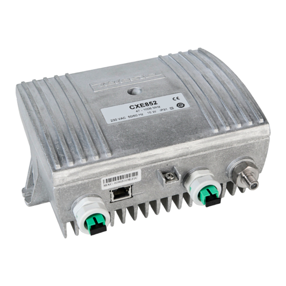
User Manual CXE85X 59300464 Rev.005 9.12.2013 4(44) Installation Housing 8912081 Figure 1. CXE85x Single / dual fibre optical receiver, 1) Optical fibre input port, 2) Ethernet port, 3) Ground, 4) Optical fibre input port 2 (CXE852), 5) RF output port The CXE85x can be installed either into a street cabinet or to a sheltered outdoor environment. -
Page 5: Powering
User Manual CXE85X 59300464 Rev.005 9.12.2013 5(44) The lid of the housing is secured by a single bolt. There are no hinges. Open lid should be removed completely. Using 4 mm Allen key, the retaining bolt is fasten with a tightening torque of 2.5...3.5 Nm. Before closing the lid ensure that: nothing is trapped between the lid and the case all case gaskets are in their correct positions... -
Page 6: Fibre Installation
User Manual CXE85X 59300464 Rev.005 9.12.2013 6(44) Fibre installation The CXE85x comes as standard with a bulkhead mounted SC/APC adapters. Fibre installation is a critical procedure and it should be done with care. Incorrect handling of the fibre can result in damage and degraded performance. Warning: The SC/APC adapter is connected to the integrated fibre receiver through a short length of fibre on the rear side of the bulkhead. -
Page 7: Front Panel
User Manual CXE85X 59300464 Rev.005 9.12.2013 7(44) Front panel 8913048 Figure 3. CXE851 front panel (2 generation) 8913055 Figure 4. CXE852 front panel (2 generation) Integrated optical receiver 1 Output test point, -20 dB directional Integrated optical receiver 2 (CXE852) - Page 8 User Manual CXE85X 59300464 Rev.005 9.12.2013 8(44) Attenuator range (Fig. 3/4 pos. 6) Slope selection (Fig. 3/4 pos. 7) 16-31 dB Flat 0-15 dB Middle sloped High sloped OLC mode jumper (Fig. 3/4 pos. 8 ) External control jumper (Fig. 3/4 pos. 11) OLC ON External control ON OLC OFF...
-
Page 9: Features
User Manual CXE85X 59300464 Rev.005 9.12.2013 9(44) Features Local user interface The local user interface consists of two/three status LEDs for optical input power and general status, a reset button, a rotary switch for midstage gain setting, three jumpers for setting the output slope, gain adjustment range and controlling the OLC and one jumper controlling the DC voltage connection at the RF output port. -
Page 10: Rf Performance
User Manual CXE85X 59300464 Rev.005 9.12.2013 10(44) The status led blinks when the RF controls are under software control and changing the rotary switch or jumpers has no effect. Hardware control can be restored using the reset button. RF output port RF output port features an “open collector output”... - Page 11 User Manual CXE85X 59300464 Rev.005 9.12.2013 11(44) Optical input selection The CXE852 optical input selection can be set to 3 modes: Automatic, Manual 1, Manual 2. When the input selection is set to the “Automatic” mode, the node automatically selects the optical input according to signal conditions. If the optical input power at the main input is out of major alarm limits, input 2 will be selected provided that its optical input power is inside major alarm limit + deadband.
- Page 12 User Manual CXE85X 59300464 Rev.005 9.12.2013 12(44) Forward path adjustment via software The mid stage gain, OLC enabling and slope setting can be taken into software control. When software control is enabled, the rotary switch and jumpers have no effect. Hardware control can be restored with reset button or via software. There are two software control modes: manual and OMI-based.
-
Page 13: Establishing Connection
User Manual CXE85X 59300464 Rev.005 9.12.2013 13(44) Establishing connection Ethernet port The Ethernet port of CXE85x supports both 10 and 100 Mbps half and full duplex standard Ethernet connection. The port has a Auto-MDI/MDI-X feature, thus the connection between CXE85x's RJ-45 port and a PC or Ethernet switch can be made with either straight or crossed cable. -
Page 14: Management Interfaces
SNMP communities. It is also possible to use a 3rd party SNMP browser / manager software to control and monitor CXE85x. The required Teleste SNMP MIBs can be downloaded from Teleste Club and SCTE MIBs from SCTE website. - Page 15 User Manual CXE85X 59300464 Rev.005 9.12.2013 15(44) Web browser Interface (WebUI) CXE85x has also a web browser user interface (WebUI) which can be used to read and adjust RF controls and to monitor the status of the unit. It is also possible to update the unit software via WebUI.
- Page 16 User Manual CXE85X 59300464 Rev.005 9.12.2013 16(44) Monitored parameters The CXE85x monitored parameters are described in the table below. SNMP traps, if enabled, are sent to user specified IP addresses. The affected LED and factory default severity settings are presented next to each parameter.
-
Page 17: Viewer Pages (Snmp Interface)
Viewer pages (SNMP interface) The CXE85x viewer is a graphical user interface that can be used to control CXE85x with Teleste CATVisor Commander PC software. The same viewers are used also by CATVisor EMS system. This chapter presents CXE85x viewer pages and the functionality of the unit. -
Page 18: Status Viewer Page
Measured optical input levels are displayed in the “Optical receiver” frame. The background colour of the “Input power” data field changes to indicate alarms. The ”Input 2 power” and “Input in use” data fields are not visible with CXE851. Measurements The measurement frame shows read-only information about the CXE85x. -
Page 19: Settings Viewer Page
User Manual CXE85X 59300464 Rev.005 9.12.2013 19(44) Settings viewer page Figure 7. CXE852 Settings page RF adjustment mode These selections control how the midstage attenuator, slope and OLC controls are adjusted: Hardware: All controls are in hardware control, settings are displayed as read- only in "RF adjustments"... - Page 20 User Manual CXE85X 59300464 Rev.005 9.12.2013 20(44) also be done via the front panel reset button. Note that these actions may result in loss of communication and the viewer needs to be closed and reopened with the new IP address. RF output power Clicking “Set limits to current value”...
-
Page 21: Communication Viewer Page
User Manual CXE85X 59300464 Rev.005 9.12.2013 21(44) Communication viewer page Figure 8. CXE85x Communication page Ethernet port Status: Shows the Ethernet port’s connection speed and duplex mode. MAC address: Shows the Ethernet port’s globally unique MAC address. SNMP communities Community names are the security method of SNMPv1 to limit access to the manageable objects. - Page 22 User Manual CXE85X 59300464 Rev.005 9.12.2013 22(44) IP address: This is a static IP address of the CXE85x and should be consistent with the LAN IP and subnet settings. The address is taken into use when IP address configuration mode is set to manual. Factory default setting is 169.254.1.1.
-
Page 23: Ntp Viewer Page
User Manual CXE85X 59300464 Rev.005 9.12.2013 23(44) NTP viewer page Figure 9. CXE85x NTP page CXE85x can use Network Time Protocol (NTP) to get the correct time automatically from a NTP server across a network. Because the CXE85x uses the time from its system clock for each SNMP trap it generates, the time should be set correctly. -
Page 24: Alarm Log Viewer Page
User Manual CXE85X 59300464 Rev.005 9.12.2013 24(44) Alarm log viewer page Figure 10. CXE85x Alarm Log page The “Alarm log” dialog box displays the alarm history for latest 16 events. All entries are date and time stamped with the most current entry at the bottom. Note that date/time information may not be correct if CXE85x hasn't received correct time. -
Page 25: Monitoring Viewer Page
User Manual CXE85X 59300464 Rev.005 9.12.2013 25(44) Monitoring viewer page Figure 11. CXE85x Monitoring page The "Monitoring" page displays all monitored parameters and their values as well as alarm limits, statuses and severity settings. See "Monitored parameters" chapter for descriptions of CXE85x alarms. Analog parameters Each monitored analog parameter of the unit is displayed in the upper half of the frame with following information in the list:... - Page 26 User Manual CXE85X 59300464 Rev.005 9.12.2013 26(44) The alarm settings are user configurable by double-clicking an analog parameter. This will open a dialog box with parameter's alarm limits and deadband that can be edited by users with at least "Service" level user rights. For others this is read-only information.
- Page 27 User Manual CXE85X 59300464 Rev.005 9.12.2013 27(44) Alarm control Alarm control frame provides independent on-delay and off-delay timers. The time delay feature can be used to eliminate false alarm triggering due to momentary disturbances. An alarm is only active when “Detection” is enabled and the monitored parameter has been over limit longer than "Delay On"...
-
Page 28: Properties Viewer Page
User Manual CXE85X 59300464 Rev.005 9.12.2013 28(44) Properties viewer page Figure 14. CXE85x Properties page The “Properties” page displays unit identification and statistics data. Identification A descriptive alias name for the node can be entered into the “Name” field, site location into “Location”... -
Page 29: Web User Interface
User Manual CXE85X 59300464 Rev.005 9.12.2013 29(44) Web user interface CXE85x has a web browser user interface (WebUI) which can be used to read and adjust RF controls and to monitor the status of the unit. It is also possible to update the unit software via WebUI. -
Page 30: Monitoring Webui Page
Rev.005 9.12.2013 30(44) viewer page” chapters for details. Because CXE851 is equipped with one optical receiver compared with CXE852 with two optical receivers this page is slightly different but contains the same functionality. After editing new settings must be taken into use by clicking "Apply" button. - Page 31 User Manual CXE85X 59300464 Rev.005 9.12.2013 31(44) HIHI: High major alarm limit HI: High minor alarm limit. LO: Low minor alarm limit LOLO: Low major alarm limit. Deadband: Specifies how much the measured value has to be on the "safe" side of alarm limit before turning off the alarm.
-
Page 32: Log Webui Page
User Manual CXE85X 59300464 Rev.005 9.12.2013 32(44) Log WebUI page Figure 17. Log page The “Log” page displays the alarm history for latest 16 events. All entries are date and time stamped with the most current entry at the bottom. The existing values are overwritten when the maximum number of entries (rows) has been reached. -
Page 33: Communication Webui Page
User Manual CXE85X 59300464 Rev.005 9.12.2013 33(44) Communication WebUI page Figure 18. Communication page The Communication page is used to configure the network of the device. IP Addressing Mode: Enable DHCP (Dynamic Host Configuration Protocol) or apply network parameters manually. With DHCP mode the IP address is assigned automatically provided that a DHCP server is installed on the network. -
Page 34: Snmp Webui Page
User Manual CXE85X 59300464 Rev.005 9.12.2013 34(44) SNMP WebUI page Figure 19. SNMP page This page is used to configure SNMP access of the device by using a SNMP manager. SNMP communities Community names are the weak security method of SNMPv1 to limit access to the manageable objects. - Page 35 59300464 Rev.005 9.12.2013 35(44) All trap parameters are adjustable also remotely via TELESTE-COMMON-MIB. Teleste MIBs are available at Teleste Club. Trap receivers IP Address: IP address of remote SNMP trap receiver. Port: Port number of remote SNMP trap receiver listening to incoming SNMP traps.
-
Page 36: Time Webui Page
User Manual CXE85X 59300464 Rev.005 9.12.2013 36(44) Time WebUI page Figure 20. Time page The CXE85x can use Network Time Protocol (NTP) to get the correct time automatically from a NTP server across a network. Because the CXE85x uses the time from its system clock for each log message it generates, the time must be set correctly. -
Page 37: Properties Webui Page
User Manual CXE85X 59300464 Rev.005 9.12.2013 37(44) Properties WebUI page Figure 21. Properties page This page reports the main specific properties of the device. Identification A descriptive alias name for the station can be entered into the “Name” field, site location into “Location” field and contact information into “Contact” field. All these fields can contain up to 63 characters. -
Page 38: Maintenace Webui Page
User Manual CXE85X 59300464 Rev.005 9.12.2013 38(44) Maintenace WebUI page Figure 22. Maintenance page Restart device The button can be used to perform a software reset of CXE85x optical receiver. This process will take ~30 s. Reset communication settings This action can be used to reset the communication settings to their factory default values. - Page 39 Rev.005 9.12.2013 39(44) New software versions for CXE85x optical receivers may be found at Teleste Club. The new versions may contain bug fixes, enhancements and completely new features. For details on each software release, see software release document also available in the Club.
-
Page 40: Cli Commands
-4 dBm Lo(4) temperature: 43 C Nominal(1 Prints units identification data. For details take a look for Viewer page “Properties”. Example: description: TELESTE CXE852 OPTICAL NODE serno: XK00051211 vendor: Teleste Corporation http://www.teleste.com properties name: CXE852 @ Salmra location: Eiger contact: www.teleste.com... - Page 41 RF parameters (For details take a look for Viewer page “Settings”.) Optical input selection: automatic / manual1 / input [auto | 1 | 2] manual2. CXE851 always returns 1. adjmode [hw | sw | Adjustment mode: hardware / software-manual /...
- Page 42 [VALUE] optical2 [enable] [hihi | Optical input 2 power value, alarm limits, enabling hi | lo | lolo | and deadband. CXE851 always all disabled. deadband] [VALUE] rflevel [enable] [hihi | hi RF output power value, alarm limits, enabling and | lo | lolo | deadband] deadband.
-
Page 43: Legal Declarations
This document is protected by copyright laws. Unauthorized distribution or reproduction of this document is strictly prohibited. Teleste reserves the right to make changes to any of the products described in this document without notice and all specifications are subject to change without notice. - Page 44 Гарантийный срок службы с момента поставки – 12 месяцев Поставщик: ГК “ПиТРИ” Москва, ул.Кастанаевская, д.62 Тел. (499) 144-00-17 http://www.pitri-tv E-mail: info@pitri-tv Гарантийный талон на ремонт (замену) в течение гарантийного срока Дата продажи_______________________________________ (дата, подпись и печать поставщика)
Need help?
Do you have a question about the CXE851 and is the answer not in the manual?
Questions and answers