Table of Contents
Advertisement
Advertisement
Table of Contents

Summary of Contents for Horizon Technology SPE-DEX 4790
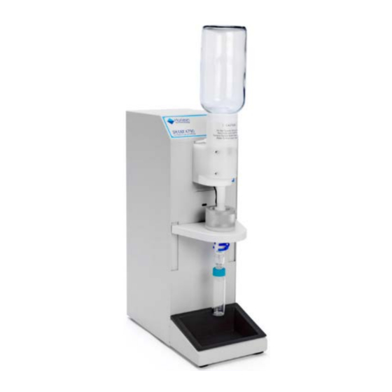
- Page 1 ® SPE-DEX 4790 Solid Phase Extraction System Service Manual...
- Page 2 Copyright © 2015 by Horizon Technology, Inc. All rights reserved. Horizon Technology, Inc. reserves the right to change the information in this document without notice. No part of this work may be processed, reproduced, or transmitted in any form or by any means, electronic or mechanical, including photocopying and recording, or by any information storage or retrieval system, except as may be expressly permitted in writing by Horizon Technology, Inc.
-
Page 3: Table Of Contents
Contents Preface ..............................4 Manual Audience and Intent ..........................4 Technical Support ..............................4 Nomenclature ........................... 6 Recommended System Maintenance ....................7 2.1. Daily Maintenance ............................ 7 2.2. Weekly Maintenance ..........................7 Troubleshooting ..........................8 Preventative Maint. Kits/ Miscellaneous Accessories ................ 14 Preventative Maintenance Procedures ..................... - Page 4 7.11. Replacing the Spring Motor (PN 50-2233) ....................52 7.12. Replacing the IR Photointerruptor (PN 16-0626) ..................54 7.13. Replacing the SPE-DEX 4790 Keypad (PN 18-0588-CE) ................55 7.14. Replacing the Control Circuit Board (PN 50-0145-CE) ................57 Schematics ............................58 8.1.
-
Page 5: Preface
Horizon Technical Support. Product Safety The SPE-DEX 4790 is designed with operator safety in mind. However, the product use is at the discretion and risk of the operator or laboratory supervisor/manager. Do not attempt to disassemble or repair the unit before reviewing this guide. - Page 6 Notes:...
-
Page 7: Nomenclature
4700 Controller or a PC-connected Envision Controller. Both are capable of controlling up to eight Modules. • System: A collection of up to eight (8) SPE-DEX 4790 Modules connected to a single controller and waste system. • Preventative Maintenance (PM): A PM is preformed yearly and is designed to maintain a full System and through the measurement of various conditions and the replacement of commonly wearable parts. -
Page 8: Recommended System Maintenance
2. Recommended System Maintenance 2.1. Daily Maintenance On a daily basis when the instrument is in routine operation: • Clean up any spills immediately using a soft, dry cloth. Follow that by wiping the area with a cloth made damp with a mild nonabrasive general purpose laboratory cleaning solution. Do not spray a cleaning solution directly onto the instrument. -
Page 9: Troubleshooting
3. Troubleshooting SYMPTOM PROBABLE CAUSE SOLUTION Module not displayed on the Data Cable not attached. Ensure that the Data Cable is Envision Operation Page. properly seated on both the Module’s and the Envision’s Data Port. Bad Data Cable. Connect the Data Cable to a different port on the Envision and see if communication can be established. - Page 10 SYMPTOM PROBABLE CAUSE SOLUTION Prewet solvent overflows. Incorrectly set Thermistors Use the Thermistor Height Tool to ensure the recommended height is set. Pressure is set too high. Verify the nitrogen source pressure is set correctly. Verify that the Solvent Bottle Pressure is set correctly.
- Page 11 SYMPTOM PROBABLE CAUSE SOLUTION stuck closed. 50-60 psi and run the Sample Drain Method. Actuate the Water Inlet Valve manually. Verify that the MAC valve is firing by disconnecting the nitrogen line on the top port of the Actuator and running the Sample Drain method (this is line A at the MAC valve).
- Page 12 SYMPTOM PROBABLE CAUSE SOLUTION System advances to Air Dry Slow sample flow rate through Verify Thermistor heights using without having processed the SPE disk. the Thermistor Height Setting entire sample. Tool. Investigate other prefiltering options. Bad Thermistor. Verify Thermistor heights using the Thermistor Height Setting Tool.
- Page 13 SYMPTOM PROBABLE CAUSE SOLUTION Solvent Sip Tube not attached to Ensure that the Sip Tube is cap. tightened into the cap. Clogged Solvent Filter Cut or pull Solvent Filter off and verify that solvent is able to be dispensed. Kinked delivery line. Inspect all lines.
- Page 14 SYMPTOM PROBABLE CAUSE SOLUTION Waste valve is stuck open. With the extractor idle, fill a disk holder with water and verify that the fluid level does not decrease. If it does, examine the Waste vessels to determine which valve is stuck open and replace that valve.
-
Page 15: Preventative Maint. Kits/ Miscellaneous Accessories
To ease the process of performing a yearly preventative maintenance (PM), the parts required are bundled into two Kits. A Module Kit allows for the maintenance of a single SPE-DEX 4790 module; Service Engineers will need to have one kit for each extractor Module. The System Kit allows for the maintenance of the external components and accessories of the System;... - Page 16 48-2605 Check Valve 48-2604 Thermistor (set of two) 30-0628 Bottle Holder O-Ring 48-2608 Rinse Needle (pack of two) 02-0692 Thermistor Clip 50-0043-02 Solvent-Waste Manifold 50-0051-02 Water-Waste Manifold...
- Page 17 120-4001-EX-THRU Solvent Manifold - Through Block Includes: • (1) Solvent Manifold: Through Block • (18) Manifold Plugs • (18) Solvent Manifold Delivery Lines • (9) Manifold-to-Manifold Delivery Lines 120-4001-EX-END Solvent Manifold - End Block Includes: • (1) Solvent Manifold: End Block •...
- Page 18 48-2772 Solvent Stone (includes ferrule) 50-2770 Manifold-to-Manifold Delivery Line (single line only; nine needed for complete set) 02-0029-01 Solvent Manifold: End Block 02-0028-01 Solvent Manifold: Through Block...
- Page 19 Hydrophilic Solution o Water-Waste Manifold o Vacuum Line Kit 48-4502 SPE-DEX 4790 Module PM Kit This kit is designed to service a single SPE-DEX 4790 module. For systems containing multiple modules, the same number of kits will be ordered.
- Page 20 o Check Valve o Check Valve Screws (3 Included) o Thermistors (set of two) o Bottle Holder O-Ring o Solvent and Water Waste Lines o Rinse Needle o Collection Adapter Screws (three Included) o Modified Water Plug...
- Page 21 o Module Feet (six included) 50-2769 Vacuum Gauge Kit This tool allows for the measurement and analysis of the condition of the subsystems for a SPE-DEX 4790.
-
Page 22: Preventative Maintenance Procedures
Prior to starting any work, it is recommended that the Service Engineer evaluate the System using the Instrument Repair Report, available upon request from Horizon Technology. This section will explain the Pre- Inspection Testing section on this form and will require that the Service Engineer is able to run the System. - Page 23 11. Starting with Module 1, run all the Modules one at a time and record their responses in the table in the Instrument Repair Report. For Prewet valves, ensure that the solvent dispenses until the level reaches the top Thermistor and then stops.
-
Page 24: Preventative Maintenance: Module
Preventative Maintenance: Module For each Module which a PM is to be performed on, a single SPE-DEX 4790 Module PM Kit (PN 48-4502) will be required. The following sections are meant to help ensure that the parts included are installed correctly. -
Page 25: Replacing The Bottle Holder O-Ring
Attach the Thermistor to the Thermistor Clip. Do the same for the other Thermistor. Set the height of the Thermistors using the Thermistor Height Adjustment Tool (see the appropriate section below). Replace the cover and screws on the Module. Note: The connection to the Main Circuit Board dictates the height of the Thermistor. If improperly set, the Prewet and Sample Processing steps may generate errors. -
Page 26: Replacing The Collection Adapter Screws
5.2.5. Replacing the Collection Adapter Screws Unscrew the three screws which hold the Collection Adapter to the Module Platform. Use the screws provided to reattach the Collection Adapter to the Platform. Note: The Collection Adapter is made of soft plastic and can have the screw holes stripped if the screws are tightened too forcefully. -
Page 27: Replacing The Module Feet
5. Replace the cover and screws on the Module. 5.2.7. Replacing the Module Feet Remove the exhaust tubing from the rear of the instrument. Lay the instrument on its side, being careful not to kink any of the external solvent tubing. Remove the old feet using either a pair of pliers to pull them off or by scraping the feet off using a knife. -
Page 28: Preventative Maintenance: System
5.3. Preventative Maintenance: System A specific point to the System PM Kit is to replace those tools which are vital to the running of the System every day. The following sections will detail the replacement of those parts which are mutual to all Modules. 5.3.1. -
Page 29: Hydrophilic Solution
5.3.3. Hydrophilic Solution Since the Water Inlet Valves are made of hydrophobic material, they are treated with a Hydrophilic Solution to ensure the rapid and complete delivery of the sample from the Sample Container to the Disk Holder. Without this treatment, the sample may not completely flow into the Disk Holder. 1. -
Page 30: Vacuum Line Kit
Note: It is critically important that vacuum supply lines are located above all lines which carry fluid to prevent the aspiration of fluid into the vacuum pump. 5.3.5. Vacuum Line Kit Through constant use, the Vacuum Lines may become occluded with solid material leading to lower vacuum and slower flow rates. -
Page 31: Post-Maintenance Inspection
5.4. Post-Maintenance Inspection After the completion of the PM, it is recommended that the Service Engineer re-evaluate the System using the Instrument Repair Report. This section will explain the Post-Maintenance Inspection Testing section on this form and will require that the Service Engineer is able to run the System. Note: The following procedures will run the SPE-DEX System through a complete run where solvent is used. - Page 32 The Water-Waste valve should activate during the Sample Processing step to remove the water. The Elution valve should activate during the Rinse steps to pull the solvent into the Collection Vessel. 11. Using the Vacuum Test apparatus and the T-Fitting, measure the vacuum as follows for each Module: Turn off the nitrogen and de-pressurize the Solvent Bottles.
-
Page 33: Service Kits And Parts List
6. Service Kits and Parts List This is a list of the service kits that can be purchased from Horizon Technology. Part # Description 50-2457 Bottle Holder (includes Bottle Holder O-Ring and Rinse Needle) 48-2607 Water Inlet Valve 48-2606 Downtube Assembly... - Page 34 25-0666 Water Inlet Valve Actuator 02-0602 Collection Adapter 50-2237 MAC Valve (includes connectors and barbs) 50-0629 Exhaust Fan (includes Molex connectors) 50-2233 Spring Motor (includes bolt and nut) 16-0626 IR Photointerrupter...
- Page 35 18-0588-CE SPE-DEX 4790 Key Pad 50-0145-CE Control Circuit Board 50-0027-03 External Nitrogen Regulator...
-
Page 36: Service Replacement Procedures
7. Service Replacement Procedures Due to the nature of use for the SPE-DEX 4790, it is recommended that proper Personal Protective Equipment (PPE) be used when servicing the System. This is to include safety glasses and gloves, but may include additional PPE based on your safety requirements. -
Page 37: Replacing The Water Inlet Valve (Pn 48-2607)
7.2. Replacing the Water Inlet Valve (PN 48-2607) PURPOSE: This work instruction will replace the Water Inlet Valve on a SPE-DEX 4790 Module. TOOLS: 5/32 inch Hex Wrench Phillips-head Screwdriver PARTS REQUIRED: 48-2607 – Water Inlet Valve CAUTIONS: Prior to beginning, the Module being worked on should have all rinse solvents drained and the lines flushed to prevent spills. -
Page 38: Replacing The Downtube Assembly (Pn 48-2606)
7.3. Replacing the Downtube Assembly (PN 48-2606) PURPOSE: This work instruction will replace the Downtube Assembly on a SPE-DEX 4790 Module. TOOLS: 5/32 inch Hex Wrench Phillips-head Screwdriver PARTS REQUIRED: 48-2606 – Downtube Assembly CAUTIONS: Prior to beginning, the Module being worked on should have all prewet and rinse solvents drained and the lines flushed to prevent spills. -
Page 40: Replacing The Sample Collect Valve (50-2498)
7.4. Replacing the Sample Collect Valve (50-2498) PURPOSE: This work instruction will outline the process to replace Sample Collect Valve within a SPE-DEX 4790 Module. TOOLS: ¼ inch Nut Driver 5/16 inch Wrench Molex Pin Extraction Tool (99-0766) Small Standard Screwdriver... - Page 41 Press Here to Unlock Rotate the valve bracket and remove the screws for the valve. Unscrew the vacuum supply from the top and side of the valve. Using the replacement valve supplied in the kit, attach the bottom vacuum line to the port on the valve labeled NC.
-
Page 42: Replacing The Solvent- Or Sample-Waste Valve (50-2535)
PURPOSE: This work instruction will outline the process to replace either the Solvent-Waste Valve or the Sample- Waste Valve within a SPE-DEX 4790 Module. The valves are identical in nature but are connected to the vacuum and electrical supplies differently. - Page 43 Remove the pins for valve that needs to be replaced. For the solvent to waste valve, remove pins 3 and 4. For the water to waste valve, remove pins 5 and 6. Refer to the pictures below for the proper removal technique.
-
Page 44: Replacing A Prewet Or Rinse Valve (50-2536)
7.6. Replacing a Prewet or Rinse Valve (50-2536) PURPOSE: This work instruction will replace a Prewet or Rinse Valve within in a SPE-DEX 4790 Module. The valves are identical in nature. TOOLS: ¼ inch Nut Driver 5/32 inch Hex Wrench... - Page 45 If this is not possible, remove the external solvent delivery lines from the unit and, using the 5/32 inch hex wrench, unscrew the entire valve block from the SPE-DEX 4790. This will allow easier access to the afflicted valve. When the valve is removed, be sure that the black gaskets do not remain in the block.
-
Page 46: Replacing The Water Inlet Valve Actuator (25-0666)
7.7. Replacing the Water Inlet Valve Actuator (25-0666) PURPOSE: This work instruction will replace the Water Inlet Valve Actuator in a SPE-DEX 4790 Module. TOOLS: ¼ inch Nut Driver Phillips Screwdriver 3/32 inch Hex Wrench PARTS REQUIRED: 25-0666 – Water Inlet Valve Actuator... -
Page 48: Replacing The Collection Adapter (02-0602)
Using a standard screwdriver, remove the (3) screws which hold the Check Valve into the Collection Adapter and set the Check Valve aside if it is going to be used again. Press down on the front platform on the SPE-DEX 4790 and, using a Phillips screwdriver, unscrew the Collection Adapter from the platform. -
Page 49: Replacing The Mac Valve (50-2237)
7.9. Replacing the MAC Valve (50-2237) PURPOSE: This work instruction will replace the MAC Valve in a SPE-DEX 4790 Module. TOOLS: ¼ inch Nut Driver 5/16 inch Wrench Molex Pin Extraction Tool (99-0766) Small Standard Screwdriver Small Phillips Screwdriver Small Wire Cutters PARTS REQUIRED: 50-2237 –... - Page 50 The line going into port “B” on the MAC Valve should come from the bottom fitting on the Water-Inlet Valve Actuator. c. The bottom line extends to the gas supply port on the bulkhead of the SPE-DEX 4790. With the tubing attached, replace the screws which hold the MAC Valve in place.
- Page 51 a. Locate the “IN” (left one shown in photo) and “EX” brass screws on the MAC Valve. b. The “IN” screw controls the rate of “open” motion of the rotary actuator. c. Turn the brass colored “EX” screw completely counter-clockwise. d.
-
Page 52: Replacing The Exhaust Fan (Pn 50-0629)
7.10. Replacing the Exhaust Fan (PN 50-0629) PURPOSE: This work instruction will replace the Exhaust Fan in a SPE-DEX 4790 Module. TOOLS: ¼ inch Nut Driver 5/16 inch Wrench PARTS REQUIRED: 50-0629 – Exhaust Fan CAUTIONS: Prior to beginning, the Controller should be turned off and the Module should have the data/power cable unplugged. -
Page 53: Replacing The Spring Motor (Pn 50-2233)
7.11. Replacing the Spring Motor (PN 50-2233) PURPOSE: This work instruction will replace the Spring Motor in a SPE-DEX 4790 Module. TOOLS: ¼ inch Nut Driver 5/16 inch Hexagonal Wrench Short Phillips Screwdriver PARTS REQUIRED: 50-2233 – Spring Motor CAUTIONS: Prior to beginning, the Controller should be turned off and the Module should have the data/power cable unplugged. - Page 54 Locate the mounting bracket and loosen the 5/16” hexagonal nut and the screw, circled in red. Swing the valve mounting bracket out of the way and, using a screwdriver, remove the four screws from the Spring Motor. Install the new Spring Motor. Pull the Spring Motor Wire over the Pivot Wheel and attach to the Platform.
-
Page 55: Replacing The Ir Photointerruptor (Pn 16-0626)
7.12. Replacing the IR Photointerruptor (PN 16-0626) PURPOSE: This work instruction will replace the IR Photointerruptor in a SPE-DEX 4790 Module. TOOLS: ¼ inch Nut Driver PARTS REQUIRED: 16-0626 – IR Photointerruptor CAUTIONS: Prior to beginning, the Controller should be turned off and the Module should have the data/power cable unplugged. -
Page 56: Replacing The Spe-Dex 4790 Keypad (Pn 18-0588-Ce)
7.13. Replacing the SPE-DEX 4790 Keypad (PN 18-0588-CE) PURPOSE: This work instruction will replace the Keypad on a SPE-DEX 4790 Module. TOOLS: ¼ inch Nut Driver Phillips Screwdriver PARTS REQUIRED: 18-0588-CE – Keypad Overlay CAUTIONS: Prior to beginning, the Controller should be turned off and the Module should have the data/power cable unplugged. - Page 57 Pull the old Keypad Ribbon upwards and out through the hole in the chassis. Insert and run the Keypad Ribbon through the chassis and route it behind the Control Circuit board. Tighten or replace all screws to the Control Circuit Board making sure to attach the KeyPad’s Grounding Wire to the bottom front screw.
-
Page 58: Replacing The Control Circuit Board (Pn 50-0145-Ce)
7.14. Replacing the Control Circuit Board (PN 50-0145-CE) PURPOSE: This work instruction will replace the Control Circuit Board on a SPE-DEX 4790 Module. TOOLS: ¼ inch Nut Driver Phillips Screwdriver PARTS REQUIRED: 50-0145-CE – Keypad Overlay CAUTIONS: Prior to beginning, the Controller should be turned off and the Module should have the data/power cable unplugged. -
Page 59: Schematics
8. Schematics 8.1. Nitrogen and Solvent Delivery System... -
Page 60: Waste And Vacuum System
8.2. Waste and Vacuum System... -
Page 61: Plumbing Schematics
8.3. Plumbing Schematics 8.3.1. MAC Valve and Water Inlet Valve Actuator Water Inlet Valve Actuator MAC Valve Supply Water Inlet Valve Status MAC Valve Line A MAC Valve Line B Closed Not Pressurized Pressurized Open Pressurized Not Pressurized... -
Page 62: Prewet And Rinse Plumbing
8.3.3. Prewet and Rinse Plumbing Valve Manifold Water Inlet Valve Assembly PW 1 PW 2 PW 3 PW 4 PW 5... -
Page 63: Vacuum Plumbing
8.3.4. Vacuum Plumbing Modified Luer Plug Collection Adapter Solvent Waste Valve Water Waste Valve Elution Valve To Waste... -
Page 64: Electrical Systems
8.4. Electrical Systems 8.4.1. Ribbon Cable All circuits within this table are run at 24 Volts. Wire Color Conn. A Pins Conn. B Pins Conn. C Pins Conn. D Pins Brown Not Used Not Used Orange Prewet 2 Yellow Not Used Green Solvent-Collect Blue... - Page 65 Conn. D Conn. C Conn. A Conn. B Conn. A Conn. B Conn. C Conn. D...
-
Page 66: Control Circuit Board Valve Indicators
8.4.2. Control Circuit Board Valve Indicators There are 16 LEDs in the top right of the Control Circuit Board. These LEDs can be used to tell if a signal is being given for a valve to fire. The LEDs are highlighted in red below. LED 1 Rinse 4 LED 9... -
Page 67: Operation Code
8.5. Operation Code 8.5.1. Prewet Cycle Start Are Prewets Sample Process Programmed Solvent-Waste Valve Opens Wait 2 s Specified Prewet Valve Opens Timer = 0 seconds Wait 5 s Solvent-Waste Valve Closes Top Thermistor Timer >= 60 Cool Timer >= 60 s seconds Top Thermistor Not Cool FAULT... -
Page 68: Sample Processing Cycle
8.5.2. Sample Processing Cycle Sample Process Water-Inlet Valve Opens Timer = 0 s Top Thermistor Cool Timer >= 45 s Wash Top Thermistor Not Cool Timer >= 45 s Timer < 45 s Top Thermistor Cool Water-Waste Valve Opens Bottom Thermistor Warm Bottom Thermistor Cool... -
Page 69: Wash Cycle
8.5.3. Wash Cycle Wash Are Washes Air Dry Programmed Timer = 0 seconds IR Sensor Not Specified Rinse Covered Covered Valve Opens Not Covered Specified Rinse Valve Opens Wait 2 s Specified Rinse Wait 8 s Valve Closes Solvent-Waste Valve Opens Wait 1 s Solvent-Waste Valve... -
Page 70: Air Dry Cycle
8.5.4. Air Dry Cycle Air Dry Water-Waste Valve Opens Programmed Time Water-Waste Valve Closes Solvent-Waste Valve Opens Wait 15 s Solvent-Waste Valve Closes Rinse... -
Page 71: Rinse Cycle
8.5.5. Rinse Cycle Rinse Are Rinses Stand By Programmed Timer = 0 seconds IR Sensor Not Specified Rinse Covered Covered Valve Opens Not Covered Specified Rinse Valve Opens Wait 2 s Specified Rinse Wait 8 s Valve Closes Wait 10 s Soak Programmed Time Elute;... -
Page 72: Available Service Documents
9. Available Service Documents Examples of the following documents are kept separately and can be furnished upon request. o PM & Service Parts Part Replacement and Recommended Inventory o Pre-Installation Requirements o Instrument Qualification / Operational Qualification o Instrument Maintenance Form...
Need help?
Do you have a question about the SPE-DEX 4790 and is the answer not in the manual?
Questions and answers