Table of Contents
Advertisement
TRAX-10 Standard Model
T
echnical Manual
Document #9821, rev. 1.00
Superior Support – Relentless Reliability
Octagon Systems Corporation, 7403 Church Ranch Blvd., Westminster, CO 80021-5490
CONTACT INFORMATION
Main Office: +1-303-430-1500
Technical Support: +1-303-426-4521
support@octagonsystems.com
www.octagonsystems.com
Advertisement
Table of Contents

Summary of Contents for Octagon TRAX-10
- Page 1 TRAX-10 Standard Model echnical Manual Document #9821, rev. 1.00 Superior Support – Relentless Reliability CONTACT INFORMATION Main Office: +1-303-430-1500 Technical Support: +1-303-426-4521 support@octagonsystems.com www.octagonsystems.com Octagon Systems Corporation, 7403 Church Ranch Blvd., Westminster, CO 80021-5490...
-
Page 2: Technical Support
It is a Condition of Sale that the use of Octagon products in life support applications assumes all the risk of such use and indemnifies Octagon against all damage. -
Page 3: Table Of Contents
Governing Law ............................17 List of Tables Table 1 - Internal Connectors and Sockets ....................8 Table 2 – TRAX-10 Mating Connectors ......................12 Table 3 - POWER Connector Pin-Out ......................12 Table 4 - DISPLAY Connector Pin-Out ......................13 Table 5 –... -
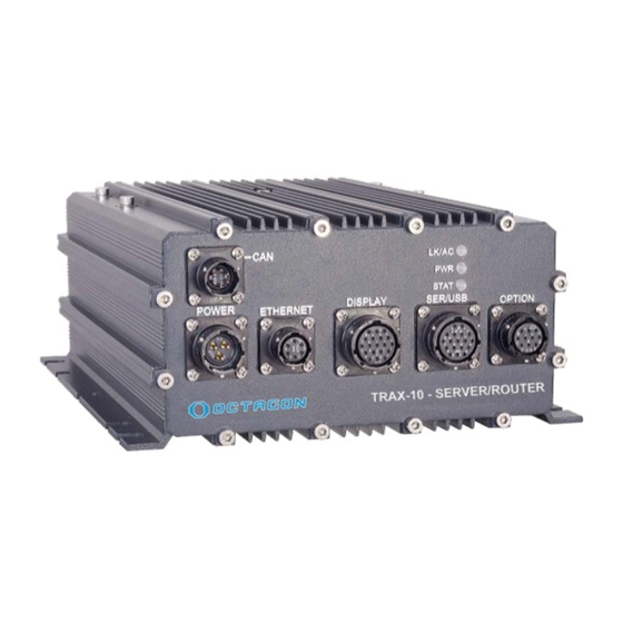
Page 4: Trax-10 Functional Overview
Other I/O includes Concurrent GPS, high resolution video, and digital. External power range is from 9 VDC to 36 VDC. Internally, the TRAX-10 has a 32 GB (or larger) solid state drive, a PCI-104 interface, a Mini PCI socket, and Mini PCI Express sockets. -
Page 5: Trax-10 Major Software Features
The TRAX-5 has an AMIBIOS BIOS optimized for the device and embedded installations. Boot Sequence The TRAX-10 can be configured to boot from native SATA SSD, a network resource, or from a USB device such as a floppy drive, hard drive, flash device, or a CD–ROM. A USB or network boot allows software installation without opening the case. - Page 6 Octagon’s warranty. 7. Do not over-tighten the antenna cable connectors. 8. The TRAX-10 includes mounting flanges that must be secured to a surface with ¼ inch or 6 mm bolts or screws. 9. The power supply cable gauge should be as large and as short in as practicable.
- Page 7 TRAX-5, 10 Case Dimensions [inches] mm Back panel shown without options Page 7 of 17 © 2016 Octagon Systems Corporation...
-
Page 8: Baseboard Connectors
J11-PCI/104 Table 1 - Internal Connectors and Sockets PCI / 104 Connector SIM card socket for J4 SATA connector SIM card socket for J5 Mini PCI socket To power supply --------------------------------- Page 8 of 17 © 2016 Octagon Systems Corporation... -
Page 9: Using The Trax-10
Using the TRAX-10 Power The TRAX-10 is rated for nominal 24V battery operation, but accepts 9V to 36V. The low end rating is for starting the vehicle. Sustained operation below 10V is not recommended. The external power cable negative and positive battery leads must be at least 16 AWG and should be stranded wire. -
Page 10: Serial Communication
Serial Communication The TRAX-10 has four serial ports. One port supports RxD, TxD, RTS and CTS. Two of the ports implement RxD and TxD. The fourth port supports RxD/TxD, RS-232 and RS-485 RS 485 operation flow chart Be aware that operating systems may assign port numbers in a different order, such as 1, 2, and 3. -
Page 11: Digital I/O
1A, 100V diode across the load, and the cathode connected to the supply voltage. The TRAX-10 also provides five digital inputs. The inputs detect a positive voltage with an input range of 0V to +Battery. The input is inactive when open (less than 100mA) and active when connected to a positive voltage of 4-36VDC. -
Page 12: Mating Connectors
Mating Connectors Table 2 – TRAX-10 Mating Connectors External Connectors Connector Function Mating Connector GPS antenna TNC-F, 50 ANT1 Wireless Accessory (optional) N-F, 50 Cellular Wireless WAN (optional) N-F, 50 Power Power Input PT06E12-3SSR or similar Display Video, Audio, USB... -
Page 13: Table 4 - Display Connector Pin-Out
COM3 GND COM1 RXD USB1 +5V COM2 TXD USB1 Data+ COM2 RXD USB1 Data- COM2 GND USB1 GND COM4 D-/TXD COM1 CTS COM4 D+/RXD COM1 RTS COM4 GND Mating Connector PT06E14-18PSR Page 13 of 17 © 2016 Octagon Systems Corporation... - Page 14 CAN1 GND CAN0 H CAN1 H Mating Connector PT06E10-6SSR Table 9 – ETHERNET Connector Pin-Out - rear panel Pin # Signal MDX0+ MDX0- MDX1+ MDX1- MDX3+ MDX3- MDX2- MDx2+ ---------- ♦♦♦ ---------- Page 14 of 17 © 2016 Octagon Systems Corporation...
-
Page 15: Opening The Trax-10
This must be done in accordance with safe and approved methods in an approved anti-static environment. Larger storage devices can only be installed as factory options. Contact Octagon Technical Support for complete instructions prior to disassembling the unit. Failure to properly reassemble the environmental protection (gaskets) will void the warranty. -
Page 16: Warranty
Octagon neither assumes nor authorizes any other liability in connection with the sale, installation or use of its products. Octagon shall have no liability for incidental or consequential damages of any kind arising out of the sale, delay in delivery, installation, or use of its products. -
Page 17: Returning A Product For Repair
5. Write the RMA number on the outside of the shipping container. 6. The customer pays for shipping to Octagon. Octagon pays for shipping back to the customer. Expedited shipping may incur costs to the customer. 7. Other conditions and limitations may apply to international shipments.
Need help?
Do you have a question about the TRAX-10 and is the answer not in the manual?
Questions and answers