Advertisement
Installation & Operations Manual
2500-12SPRVSR
2500-16SPRVSR
2500-28SPRVSR
2500-36SPRVSR
Made in the USA
2 Year Warranty
360° Supervision System
N56W24720 N. Corporate Circle
800-451-1460
www.area-of-refuge.com
2500-56SPRVSR
2500-76SPRVSR
2500-92SPRVSR
Sussex, WI 53089
262-246-4828 (fax)
www.rathmicrotech.com
RP8500SPRVSR
Ver. 3
10/17
Advertisement
Table of Contents

Summary of Contents for Rath 2500-12SPRVSR
- Page 1 Installation & Operations Manual 360° Supervision System 2500-56SPRVSR 2500-12SPRVSR 2500-76SPRVSR 2500-16SPRVSR 2500-92SPRVSR 2500-28SPRVSR 2500-36SPRVSR N56W24720 N. Corporate Circle Sussex, WI 53089 RP8500SPRVSR 800-451-1460 262-246-4828 (fax) Ver. 3 Made in the USA www.area-of-refuge.com www.rathmicrotech.com 10/17 2 Year Warranty...
- Page 2 Thank you for purchasing Rath’s 360° Supervision System. We are the largest Emergency Phone Manufacturer in North America and have been in business for over 35 years. We take great pride in our products, service, and support. Our Emergency Phones are of the highest quality.
- Page 3 Wiring For 12-36 Zone System: NOTE: For 12-16 Zone Systems (1) 2500 Supervisor Board is included, for 28-36 Zone Systems (2) 2500 Supervisor Boards are included. Wiring For 56-92 Zone System: NOTE: For 56 Zone Systems (3) 2500 Supervisor Boards are included, for 76 Zone Systems (4) 2500 Supervisor Boards are included, and for 92 Zone Systems (5) 2500 Supervisor Boards are included.
- Page 4 4. Secure the cables using provided cable ties. 5. Attach supplied +12vdc Power Supply to appropriate terminals on 2500 Supervisor Board. Insert the + wire into the + connector and - wire into the RETURN connector on board and secure by screwing down the capture clip.
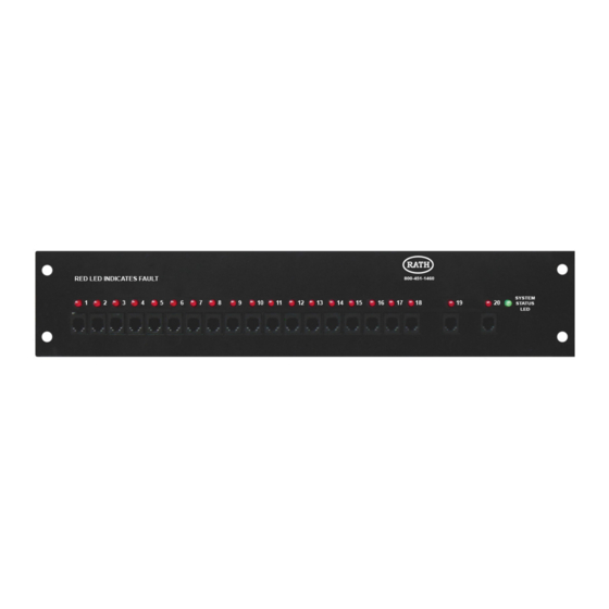
- Page 5 6. Ensure switches for monitored ports are set to proper positions. The system comes from factory with switches in “DISABLE” position. If port is to be monitored, slide switch to “ENABLE”. Switches on positions 19 and 20 are for central office (telephone) lines, Base Station phone, or phones. 7.
- Page 6 9. Mount swing-mount bracket to wall using appropriate fasteners (skip this step if mounting 2500 Supervisor Board in 19” rack). 10. Attach 2500 Supervisor Board to mount using screws removed in step 2. 11. Plug feeder cables into Distribution Module. 12.
- Page 7 Typical System Wiring Diagram Page 6...
Need help?
Do you have a question about the 2500-12SPRVSR and is the answer not in the manual?
Questions and answers