Table of Contents
Advertisement
Quick Links
Advertisement
Table of Contents

Subscribe to Our Youtube Channel
Related Manuals for Murideo Fresco SIX-A


Summary of Contents for Murideo Fresco SIX-A
- Page 1 Page 1 of 35 Murideo Fresco SIX-A – Advanced HDMI 2.0 & HDCP 2.2 Tester & Signal Analyzer Murideo Fresco SIX-A Advanced HDMI 2.0 & HDCP 2.2 Tester & Signal Analyzer User’s Manual Version 1.00 Call the AVPro Team at –North America 877-886-5112 International +1-605-274-6055...
- Page 2 Page 2 of 35 Important Safety Information • Follow all instructions • Use only a dry cloth to clean • Use caution not to block side vents on unit • Indoor use only: To reduce the risk of electric shock, do not use near water or expose to rain or moisture. Keep away from excess moisture • Do not use near heat sources such as room heaters, hot A/V equipment • Read all warnings • Use only accessories provided by Murideo • Unplug the device during lightning storms or when unused for long periods of time • Keep away from open flames • Protect all connected cords including power cords from being pinched, compressed, and stepped on • Do not open the case. All servicing should be done only by qualified and approved service personnel • Electrical Input Rating: Power over 5Vdc 700mA. Caution: Use only the supplied AC/DC Adapter. • Operating temperature range: e.g. 0 to 40 C. • For charging use the provided 5Vdc 3A supply only. • To disconnect power sources, remove the AC/DC adapters from the wall outlets. Attention: 1. In order to protect your SIX-A and complete system under test from possible damages, please don't turn on the SIX-A power switch before analyzer Input is attached to tested device (source, repeater, AVR, Blu-Ray, Streamer, etc.) output. Please make sure that...
-
Page 3: Table Of Contents
What’s in the Box? .......................... 5 Input/Output ............................ 6 Buttons & Indicators (see picture next page).................. 6 Connecting the Murideo SIX-A to SUT (Source Under Test) ............7 PC Software (Included): ....................... 17 HDMI Tips for Installers ......................27 Murideo Fresco SIX-A API ...................... -
Page 4: Overview
Page 4 of 35 Overview Thanks for purchasing the Murideo SIX-A! The Murideo SIX-A is for the AV integration market to troubleshoot, analyze and commission digital AV distribution systems up to HDMI 2.0(a) and HDCP 2.2 operation up to the 18 GBPS level. Pair the 6A with the 6G (generator) and you have the perfect "fox and hound" point-to- point troubleshooting system available today. One of the biggest challenges for integrators today is determining what infrastructure to put in the systems they design and further verifying that all of the components will work together. Over the past few years UHD TVs have been a mix of HDCP 2.2 and 1.4, 300MHz and 600MHz – even to the point of varying by port. The SIX-A takes the guess work out of the equation and provides absolute information about HDMI components that will work and IDs ones that won’t work – all in a hand-held, affordable, portable field tool. The SIX-A is designed to be extremely accessible shipping with free control software, plus front panel controls that allow access to 90% of the features. High bandwidth cable testing is simple with the 6A and also necessary with the release of HDMI 2.0(a) - make 100% sure your cables are good before you send Sparky out to the job site. Call the AVPro Team at –North America 877-886-5112 International +1-605-274-6055... -
Page 5: Key Features: Murideo Fresco Six-A
Page 5 of 35 Key Features: Murideo Fresco SIX-A – Advanced HDMI 2.0 & HDCP 2.2 Tester & Signal Analyzer • Analyze any HDMI/DVI signal up to 18 GBPS (4096x2160P60 4:4:4) • Test HDMI/DVI Cables up to 18 GBPS - Full TMDS Testing • View up to 18 GPBS Video Content & Format Info - Anywhere • Test/Analyze HDBaseT Signal Integrity & Report HDBaseT Data • Read & Analyze HDR Signals & Metadata • Report & Analyze InfoFrames • Analyze & Report HDMI Distribution System over Time (minutes, hours, days) - Down to the Pixel • Advanced EDID Analysis & Tools • Hot Plug Detect Setting • HDCP Analyzer - 2.2, 1.X, Disable • Audio Tests - 2-Channel & Multichannel • Audio VU Meter • Pixel Color Checker • Portable, Battery Operated • CEC Testing • Printable Reports Pair the SIX-A with the SIX-G and you have a test suite ready to tackle even the toughest troubleshooting jobs out there ! What’s in the Box? -
Page 6: Input/Output
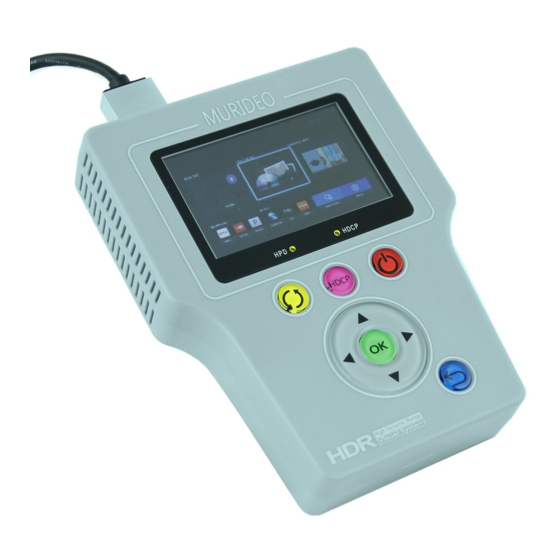
Page 6 of 35 Input/Output 1. Power in : 5VDC @ 3A adapter 2. Batteries Included - Unit runs off internal batteries and is recharged via supplied power adapter. You can also leave the power source connected during use. 3. Charging Indicator – on top of unit: a. Red – Unit is charging b. Green – Unit is charged c. Front button – OK then Left Arrow – shows charge level bars. 4. Control – connect USB micro cable from Control Port to PC for use of SIX-A PC Software or other 3 party control system. 5. RS232 – Use to connect the supplied 3.5mm to 9-pin serial adapter to a PC or 3 party controller for RS232 operations – not normally used for standalone operation. 6. L/R Out – 3.5mm Provides Line Audio output (L/R) – Not normally used for standalone operation. 7. HDMI in – For connecting to an HDMI source (BluRay, UHD Player, Streamer, PC, etc.) Can also be connected to any repeater output for troubleshooting distributed systems – baluns, extenders, HDBaseT, HDIP, matrices, distribution amps, etc. Buttons & Indicators (see picture next page). 1. 3” OLED Display: a. -
Page 7: Connecting The Murideo Six-A To Sut (Source Under Test)
Page 7 of 35 is highly recommended that any HDTV you purchase is compatible. Current versions of HDCP are 1.4 and 2.2. The Murideo SIX-A handles both. 4. Quick Select (Yellow) – This button is used to quickly select various 6A functions that will be covered below. 5. HDCP (Magenta) – Used to Select HDCP 1.X, HDCP 2.2 or Disable (no HDCP). 6. Power (Red) – Hold down for a few seconds to power on or power off the unit. 7. OK Button (Green) – Press to enter the menu and then use left and right arrows to navigate through menu pages and up and down arrows to select specific items in menu. Pressing OK again selects the menu item. 8. Up/Down/Left/Right Arrows – during normal operation use up and down arrows to navigate through test patterns. 9. Exit Menu (Blue) – Use to go back or exit menus. Connecting the Murideo SIX-A to SUT (Source Under Test) The SIX-A can be operated manually (front panel buttons) or via PC interface (software provided with unit and available at murideo.com). Manual Operation Connection 1. Connect the provided AC power adapter to the analyzer and plug into AC power (110V- 220V) or power the analyzer using the internal battery. 2. Connect the HDMI cable between the analyzer and SUT. 3. You are now ready to power up the analyzer and SUT and proceed with analysis functions. a. The display will show the horizontal and vertical pixel format and refresh rate (ex. 3840x2160P 29.999 Hz) momentarily then the live video coming from the SUT. - Page 8 Page 8 of 35 The HPD light will be ON and the HDCP light will be ON if HDCP is enabled on the SUT. PC Software Application Connection You will need a SIX-A, a PC with the application installed, supplied HDMI cable, supplied USB cable, and supplied AC power adapter. 1. Connect the SIX-A to it AC power adapter. 2. Connect the SIX-A to the PC using the supplied USB cable or alternatively supplied RS-232 cable terminated with DB 9 female receptacle (in case if your host PC does have physical Serial COM Port). 3. Connect the SIX-A Input to the unit under test using an HDMI cable. Menu System – When the SIX-A initially boots up you will see a splash screen with firmware revision followed by the resolution and timing of the SUT, followed by the live video or test pattern from the SUT or generator (ex. SIX-G). Menu Timeout – The on screen menu will exit after 20 seconds. After 1 minute of device inactivity display goes black to conserve battery charge – pressing any button will wake it up immediately. Unit Sleep/Shutdown – The unit will completely shut down after 10 minutes of no activity. This is to conserve battery charge and to avoid overheating if you put it back in the case without powering down. Navigation – To navigate the SIX-A menu system start by pressing the OK button or the yellow shortcut button. From there use the left and right arrows to scroll through the menu system. Use the up and down arrows to navigate through sub menu items and use the OK button to execute analyzer functions. Use the return button to return to live video. Menu Pages/Analyzer Functions – for the purpose keeping with the order below once in the menu use the right arrow to navigate and use the OK button to enter menu system. 1. Signal Info - provides the following basic info on the SUT. a. Timing – Horizontal & Vertical Pixel Count, Progressive or Interlaced Video info, and Refresh Rate (ex. 3840x2160P 60Hz) b.
- Page 9 Page 9 of 35 c. Video Type – HDMI or DVI d. HDCP – Displays HDCP type (ex. 1.X or 2.2 or None) e. Color Depth – Display the bit depth of the signal (ex. 8-bit, 10-bit, 12-bit, 16-bit. Bit Depth, aka Color Depth, describes the amount of information stored in each pixel of data. As you increase bit depth, you also increase the number of colors that can be represented. In the case of an 8-bit RGB image, each pixel has 8-bits of data per color (RGB), so for each color channel the pixel has 2 = 256 possible variations. In the case of a 10-bit RGB image, each color channel would have 2 1024 variations. Sometimes manufacturer documentation refers to 8-bit as 24 bit and 10-bit as 30 bit, etc. – they are both correct and mean the same thing ex. 8 x 3 (Red, Green & Blue RGB) = 24. f. TMDS Bandwidth – Displays the total bandwidth of the source under test – ex. A 720P requires about 2.2 GBPS of bandwidth, 1080P about 4.5 GBPS and a 4K signal would require between about 9 to 18 GBPS depending on refresh rate and chroma subsampling. More on this later in the troubleshooting section. g. HDR Metadata – This indicates that HDR is present. If the status is “Present” this indicates that valid HDR Metadata is present. If the status is “Invalid” the metadata is not present or incorrect. You can examine the HDR Infoframe in the PC Software under “Utilities” h. Audio Sampling Frequency – Displays the audio sampling frequency (ex. 48K, 88K, 176K, etc.) Sample rate is the number of samples of audio carried per second, measured in Hz or kHz (one kHz being 1000 Hz). For example, 44 100 samples per second can be expressed as either 44 100 Hz, or 44.1 kHz. Bandwidth is the difference between the highest and lowest frequencies carried in an audio stream. i. Audio Sampling Size – Displays the audio sample size (ex 16-bit, 24-bit). Using 16- bit digital audio, for example, each one of those samples has 16-bits worth of data, or 2 (65,536) possible positions it can record, from the lowest position to...
- Page 10 Page 10 of 35 2. Pixel Color Checker – Used to check the accuracy of an input video signal from any other device. So if you're wondering about the accuracy of your Blu-ray player, you can connect the 6A to the output of the player. Using a calibration disc on the Blu-ray player, you can enter row (horizontal pixels) and column (vertical pixels) information to read the exact color coordinates or RGB triplet values for any pixel on the screen. The 6A color checker will ID player-induced errors that can affect calibration discs, it can help diagnose color decoding errors in other devices as well. Alternatively, a reference SMPTE Bar pattern can be injected into a distribution system with the Murideo SIX-G and decoding errors can be identified throughout the system. Color Checker Usage: Call the AVPro Team at –North America 877-886-5112 International +1-605-274-6055...
- Page 11 Page 11 of 35 a. Press OK Button to select/enable b. Use up/down arrows to enter horizontal pixel location (ex in 720P format set to 712) c. Use left/right arrows to enter vertical pixel location (ex. In 720P format set to 1276) d. Press OK e. RGB Triplet Value will be displayed R:008 G:008 B:008 – in an 8-bit system this would be almost black (Black RGB are all 0 and White RGB all 255). 3. Signal Monitor – This is an abbreviated test for signal loss and frame to frame difference in an HDMI distribution system. This can be used to diagnose intermittent issues in a system caused by defective sink, source or repeater and their handling of HDMI and HDCP handshake and key exchange. This can also be used to identify external devices causing interruption to the signal – ex. EMI (Electro-Magnetic Interference) from an HVAC transformer in a commercial facility the “interferes” with the HDMI distribution system and cause loss of HPD or 5V. The Signal Monitor, when placed in the system will record the exact minute or second when the error occurred. The Signal Monitor can record information for up to a year (361 days and 6 hours), collecting actionable information for diagnosing component or external problems in the system. Call the AVPro Team at –North America 877-886-5112 International +1-605-274-6055...
- Page 12 Page 12 of 35 Signal Monitor Usage: a. Setup – scroll up/down to select: i. New Start – start a new test ii. Time Slot – press OK first, then cursor will be on Time Slot, from there use up/down to set at either 1 second or 1 minute – this is the recording intervals for performing the test for signal loss. iii. Working Status – Indicate that the test is active (working) or stopped (inactive). iv. Total Number – this is the number of tests run based on the interval/time slot selected. v. Trigger Number – This is the number of errors detected – should be all 0’s if system is working correctly. Will show the number of errors to total number of tests 58/0 would mean 58 tests and 0 errors or when there are errors it would show 58/2 or more than 0. 4. VU Meter - A volume unit (VU) meter or standard volume indicator (SVI) is a device displaying a representation of the signal level in audio equipment. The Acoustical Society of America standardized it in 1942 (C16-5 - 1942) for use in telephone installation and radio broadcast stations. The VU meter on the SIX-A displays channel volume on up to 8 channels embedded in the HDMI signal and relative level expressed in dB (decibels). VU Meter Usage: View meter – will show dB level of each channel. Adjust level at AVR or Amplifier for each channel. Call the AVPro Team at –North America 877-886-5112 International +1-605-274-6055...
- Page 13 Page 13 of 35 5. Cable Test - To use the cable test function you must also have the Murideo SIX-G as a source. The HDMI Cable test is powerful tool for pre-installation testing of desired cables and extenders. The SIX-A tests cables up to 18 GBPS and does complete bit error rate testing on cable under test or link between HDMI extenders - HDBaseT or HDIP. What are the 4K formats supported by HDMI 2.0? The SIX-A tests for and identifies the highest possible bandwidth the cable or link is capable of passing, giving you 100% confidence that the system you install works. The chart above from HDMI.org shows formats supported by HDMI 2.0. The chart below shows limitations of extending over CAT with HDBaseT. Systems Integrators should keep this information in mind when designing and retrofitting systems. Bandwidth requirements for video signals Frame Chroma Pixel 8-bit 10-bit Resolution Rate Subsampeling Clock color color Remark 720P / 74.25 2.23 2.78 1080I 60Hz...
- Page 14 Page 14 of 35 Cable Test Usage: From the Cable Test Menu Screen a. Plug the SIX-G into one end of the cable to be tested or into the HDMI Transmitter (input) port on the link device (balun/extender) in the link to be tested. b. Plug the SIX-A into the other end of the HDMI cable or the HDMI Receiver (output) port of the link device (balun/extender) in the link to be tested. c. Press OK button on the SIX-A to start test - SIX-G requires no interaction as the SIX-A automatically controls the test and requirements for both devices. d. The following tests are completed: 5V - This checks to make sure the required 5V DC signal is present and passed from Source to Sink 2160P60 (18G) - This completes a bit error test at the highest data rate that will pass though the best HDMI cables. This will not pass through an extended HDMI link as of this writing. iii. 2160P30 (9G) - This completes a bit error test at 9 GBPS 1080P60 (4.5G) - This completes a bit error test at 4.5GBPS 720P60 (2.2G) - This completes a bit error test at 2.2GBPS 480P60 (1G) - This completes a bit error test at 1 GBPS vii. DDC - Pass/Fail - The Display Data Channel (DDC) is a communication channel based on the I²C bus specification. HDMI specifically requires the device implement the Enhanced Display Data Channel (E-DDC), which is used by the HDMI source device to read the E-EDID data from the HDMI sink device to learn what audio/video formats it can take. HDMI requires that the E-DDC implement I²C standard mode speed (100 kbit/s) and allows it to optionally implement fast mode speed (400 kbit/s). The DDC channel is actively used for High-bandwidth Digital Content Protection. viii. HPD - Pass/Fail - The hot plug detect channel, which uses one pin, senses when you plug in or unplug a device, re-initializing the HDMI link if necessary. The one-pin display data channel (DDC) carries device information and the HDCP encryption information discussed in the previous section. Other channels carry encryption data and electricity to power communication between devices. Call the AVPro Team at –North America 877-886-5112 International +1-605-274-6055...
- Page 15 Page 15 of 35 Figure 1 - HDMI Under the Hood At this writing (May 2016) many cables will not pass 18 GBPS data and in fact we have only seen cables up to about 11M pass the full bandwidth signal. Test all cables and links in the system to verify and document throughput and system compatibility. Call the AVPro Team at –North America 877-886-5112 International +1-605-274-6055...
- Page 16 Page 16 of 35 6. Audio Volume - This controls the audio output level on the SIX-A - use this for audio confidence testing. 7. Auto Power Off - This function allows you to bypass the auto sleep and shut down functions. These functions are designed to save battery life; however, some integrators don't like auto shutdown so it can be disabled. Options are Disable and Enable. 8. Input Standby - This allows you to turn off the input connected to the SIX-A - this is great for creating a hot plug event without having to physically disconnect from the system. Options are Standby Off and Standby On. 9. EDID Setup – This function is used to make the analyzer emulate any display – there are several fixed or test EDIDs with common attributes and 10 USER defined EDIDs that you can pull from any display with the COPY EDID function. This will be covered in depth in the troubleshooting guide and in a video on murideo.com 10. Copy EDID – This function is used to COPY an EDID from ANY display – you can copy 10 USER EDIDs into the device. These EDIDs are placed in non-destructive memory locations. USER EDIDs can be used to emulate/duplicate any display. This is helpful if you need to verify a distribution system prior to actual delivery of the displays or projectors. 11. HPD Setup - The HPD (Hot-Plug-Detect) feature is a communication mechanism between a source and a sink device that makes the source device aware that it has been connected/disconnected to/from the sink device. When an HDMI cable is inserted between the two devices, the resulting hot-plug detection instantiates a start-up Call the AVPro Team at –North America 877-886-5112 International +1-605-274-6055...
-
Page 17: Pc Software (Included)
12. HDCP Setup – High-bandwidth Digital Content Protection (HDCP) is a form of digital copy protection developed by Intel Corporation to prevent copying of digital audio and video content as it travels across connections. This is used to emulate type required to pass protected content (movies). The options are : a. HDCP Auto – Means both HDCP 1.X and 2.2 will be accepted from the source b. HDCP 1.X Enable – Means ONLY HDMI 1.X signal will be accepted. c. HDCP 2.2 Enable – Means ONLY HDMI 2.2 signal will be accepted d. HDCP Disable – Means only signals with NO HDCP will be accepted. This is a great tool for troubleshooting HDCP issues and lets you emulate any HDCP scenario in the field. 13. Battery Stats – Provides a bar graph of battery charge level. PC Software (Included): PC Interface - This is a program that works with the Murideo SIX-A. It is a free download from the murideo.com website (under SIX-A product page) The PC software lets you control the unit from your PC (Mac – use Parallels, Bootcamp or other PC emulator). Connection – Connect from your PC USB port to the SIX-As USB Micro port with the supplied cable. No driver installation is required. USB is serial under the hood and the SIX-A will show up as a COM port in Device Manager. If for some reason your PC can’t find the driver, you can download one from the products webpage at murideo.com. Run – The program by double-clicking on the SIX-A Icon. The program can be downloaded from the Murideo.com website if you don’t already have it. Call the AVPro Team at –North America 877-886-5112 International +1-605-274-6055... - Page 18 Page 18 of 35 PC Software Usage: 1. Opening Screen: (Timing Tab) Use: 1. To connect (to your SIX-A) click on SEARCH MACHINE – this will find the COM port & change the COM Port light to RED as seen above. 2. Status Panel (Left Side Of Screen)- The status panel is viewable from all pages and is on the left side of the screen. a. Close Port – press to close the serial connection (disconnect from the unit). b. COM Port – this is a drop down menu for direct selection of COM port if known c. Search Machine – This button is used to search all COM ports (1-100) from a valid SIX-A device and connect to it. Call the AVPro Team at –North America 877-886-5112 International +1-605-274-6055...
- Page 19 Page 19 of 35 d. Address & Address Management – This would only be used if you have and want to manage several SIX-As in a testing environment. Use the function to name and number multiple SIX-As. See below for test system connections. Creating test system with multiple SIX-A and allowing 3rd party system integration. For the purpose setting up large test system with multiple SIX-A, we provided Serial port via 3.5 mm, 3 pin receptacle and supplied PC Control software mechanism for Serial identification for each connected SIX-A device. We also supplied a proprietary serial cable, terminated on one side with DB9 (9 pin connector and on the other side with 3.5mm (aka: Mini Stereo Jack) with 3 contacts. Serial Connection diagram: e. Input Port On/Off – This is a quick way to renegotiate the entire HDMI connection sequence f. Volume – This allows you to increase and decrease the OUTPUT audio volume of the device. This only works if you are connected to a set of headphones, and audio receiver or amplifier. g. Received Signal Info – This provides a snapshot of the HDMI signal connected to the SIX-A. i. HDCP ii. HDMI/DVI iii. Timing iv. Color Space v. Color Depth vi. 2D/3D Call the AVPro Team at –North America 877-886-5112 International +1-605-274-6055...
- Page 20 Page 20 of 35 vii. Audio Sample Rate viii. Audio Bit Sample Size ix. Audio Type x. Audio Channels (number) 3. Timing Details Tab – This will give you detailed information about the signal you are Analyzing (see screenshot below): a. Video Timing Diagram – This is a static image of the timing signals and is for reference only (does not change). b. Download Image – This will update the video frame when pressed. c. Color Checker – After you “Download Image” you can see the RGB Triplet color of any point of the image by: i. Pointing and clicking anywhere on the image ii. Using the up/down/left/right arrows iii. Directly inputting a pixel location d. Save (after you download an image) – This will save the current frame as .bmp for further analysis or editing. This is useful for creating/editing test patterns, or examining color performance of various repeater devices (AVR, Switch, etc…). The image is saved into the directory where you have the software and save like this: img16-5-26-21-46-37(1920x1080).bmp (Year-Month-Day-Hour-Minute- Second-Resolution). e. Update Status – This will update the timing information displayed and the Received Audio and Video information.
- Page 21 Page 21 of 35 4. Utilities Tab – For advanced troubleshooting please see CEA-861.3 – HDR Static Metadata Extensions and CEA-861-F – A Detailed Profile for Uncompressed High Speed Digital Interfaces. We will also be coving InfoFrames in our soon to be released troubleshooting guide that will be available on the SIX-A webpage at murideo.com. See screenshot below of utilities tab. a. HDMI InfoFrames - An InfoFrame packet carries one InfoFrame. The InfoFrame provided by HDMI is limited to 30 bytes plus a checksum byte. HDMI Sources are required, in some cases, to use the Auxiliary Video information (AVI) InfoFrame and Audio InfoFrame and recommended in other cases. Other InfoFrames specified in CEA-861-D are optional. All InfoFrames are described in detail in the CEA-861 standard. b. HDMI InfoFrame Analysis Report : If further information is available, the space on the right will give the details (See HDR Infoframe Analysis image on page 23) c. HDMI sources and sinks are expected to use two basic InfoFrames: i. AVI (Auxiliary Video Information) InfoFrame Communicates Colorimetry, Picture aspect ratio, Pixel-Repetition factor, RGB or YCbCr indicator, and others specified within 861B standard. Call the AVPro Team at –North America 877-886-5112 International +1-605-274-6055...
- Page 22 Page 22 of 35 ii. Audio InfoFrame Communicates, Channel count, Coding Type, Sample size, Sample frequency, Channel allocation and other audio specific information. iii. There are other types of InfoFrames that are supported by the 861 standard, but are optional with respect to HDMI specification. Call the AVPro Team at –North America 877-886-5112 International +1-605-274-6055...
- Page 23 Page 23 of 35 5. Monitor Tab – Signal Monitor – is designed to monitor the HDMI signal traffic over time. Many HDMI issues that present the toughest challenges in the field are intermittent. Many of these issues can be traced back as an interruption in the HDMI handshake. The HDMI handshake is the exchange of encrypted keys (HDCP) between the source / player and the Display (sink) and HDMI Distribution equipment (repeaters). Each device features a unique set of keys which need to be accepted by the display and source before video/audio is displayed. HDMI Handshake issues occur when the display or source does not accept the keys from HDMI Distribution equipment. Signal Monitor Usage: a. Time Slot Setting – enter and interval and select either seconds or minutes – this will calculate the total testing time in the box below the settings. Example 1 and Seconds would sample the signal every second for a total of 34 minutes. b. Trigger Mode – Select by frame image difference if you are using a generator like the SIX-G with a static image. Select loss of signal if you are injecting into a system with live video content (changes from frame to frame). c. New Start – Press this button to start the test Call the AVPro Team at –North America 877-886-5112 International +1-605-274-6055...
- Page 24 Page 24 of 35 d. Read Status Record from Device – This button will poll the device and pull the test data for display on the screen below – in the example below showing 000000000000, this means there are no errors. e. Interpreting Results – 1 = ERROR, 0 = NO ERROR. If you look at the start time and know the interval (time slot) and units (seconds or minutes) you can identify exactly when the error occurred. Example (from above): Test started on May 27 at 8:37 and 32 seconds – the far left 0 is second number 33, then 34, then 35 and so on. This will track and is easy to calculate based on ANY time slot setting. Once you have this up and running (can run for up to a year) you can easily go back and analyze the results. A practical example would be a system where your customer complains about certain times of day when the TV flashes or drops audio, but it’s hard to pin down since every time you go out to the site its working – a real intermittent issue. By placing the SIX-A on the output side of whatever is feeding the intermittent display (AVR, Switcher, UHD Player, etc.). Run Call the AVPro Team at –North America 877-886-5112 International +1-605-274-6055...
- Page 25 Page 25 of 35 the test for about 24-48 hours (or longer) and look for any 1’s (errors) generated. Then track the errors to the time they occurred and start looking for repetition – every 3 hours and 22 minutes and 33 seconds the error occurs in the HDMI bit stream. What is going on in the dwelling every 3 hours and 22 minutes? Large transformer is kicking on, HVAC, something generating EMI/ESI? Once you identify the problem you can fix it. In this example using shielded CAT5 may solve or moving components away from devices causing interference. There are hundreds of uses for this feature and we will be covering many in depth in our soon to be released troubleshooting guide. 6. EDID Tab - Extended Display Identification Data (EDID) is a data structure provided by a digital display to describe its capabilities to a video source (ex. graphics card or set-top box). It is what enables a modern personal computer to know what kinds of monitors are connected to it. Additionally, a modern consumer electronic source will “read” the EDID to determine the preferred format information to send to the display. A sample EDID for a Samsung UHD TV is shown below. Call the AVPro Team at –North America 877-886-5112 International +1-605-274-6055...
- Page 26 Page 26 of 35 a. The EDID function on the SIX-A is used to read, write, copy, store and manipulate EDIDs to gain a clear picture of what exactly is happening with regards to all sinks, sources and repeaters in the system. Most of these functions are available on the SIX-A itself. The PC program allows you to store/retrieve EDID files on your hard drive and write EDIDs to the SIX-A. b. Open File – This will allow you to access previously saved EDIDs. The EDID files are by default saved in the directory where you installed the PC software. The file you are looking for is a .bin file. You can rename these files to match the display model number you are dealing with. c. Save to File – This will save the EDID that is display on screen to the directory where you installed the SIX-A PC software: Once the file is saved you can rename it to match the display and model number. New firmware will be released soon to allow naming from the PC Software and SIX-A. d. Write to USER EDID – This writes the EDID displayed on screen to the USER EDID (1-10) on the SIX-A. a. Use EDID Selection to select USER EDID to write to device (1-10) Call the AVPro Team at –North America 877-886-5112 International +1-605-274-6055...
-
Page 27: Hdmi Tips For Installers
Page 27 of 35 b. Read EDID from file (open file) or use the EDID that is on screen c. Write to USER EDID – this will add the EDID to the SIX-A and will be accessible under the USER Number (1-10) where you stored it. e. Read EDID from Device – This will allow you to read an EDID from the device. This is useful when you captured several EDIDs (up to 10) in the field and want to back them up on your PC. a. Use EDID Selector to pick the EDID you want to read. b. Once on screen you can now save it to a file. Note: EDIDs can be modified from your PC and then loaded into the generator for troubleshooting and emulation of potential issues. There are several utilities out there that allow you to write EDIDs directly back to the display, however, we strongly discourage this as you can potentially BRICK the TV. If you identify an EDID problem, it is best to contact the manufacturer for resolution. WARNING – EDID WRITE UTILITIES CAN DESTROY YOUR DISPLAY, MOTHERBOARD, OR OTHER CONNECTED HARDWARE IF RUN INCORRECTLY. Be very sure you understand what you are doing before using one of these EDID write utilities. HDMI Tips for Installers • Use Active equipment over Passive wherever possible • Insure all devices are on the most recent firmware • Insure all devices are on the same AC circuit if possible • Keep solid HDMI runs under 25ft (use 24AWG) and go to HDBaseT extenders for runs over 25'. • Use best cabling possible, the higher bandwidth the better. • CAT5e or better - use shielded (STP) when you are not absolutely sure what is behind the Call the AVPro Team at –North America 877-886-5112 International +1-605-274-6055... - Page 28 Page 28 of 35 wall. • Use only solid copper CAT cables - no CCA. • Don’t over complicate the system with too many devices in series. Too many handshakes cause unexpected and unwanted results. • Try to buy all the HDMI devices and HDMI cables from one vendor as they have been tested with each other assuring system interoperability. • Cycle power on all devices in the system - this will cause a hot plug event and will cause the source to read the sink EDID again and possibly return the system to normal operation • Make sure everything in the system is HDCP 2.2 compliant in a UHD distribution system. • Clock stretching issues are common in some STB with older HDMI chipsets (although they look new). This will cause a no picture situation. You can use EDID minder to fix this, and some connectivity companies’ even list a fix for clock stretching as a feature in extenders and matrix switches. • When using POE extenders - make sure they are IEEE 802.11af - this ensures that you don't damage downstream or upstream components. Call the AVPro Team at –North America 877-886-5112 International +1-605-274-6055...
- Page 29 Page 29 of 35 Murideo Fresco SIG-A – Advanced HDMI 2.0 & HDCP 2.2 Tester & Signal Analyzer • Analyze any HDMI/DVI signals up to 18 GBPS (4096x2160P60 4:4:4) • Test HDMI/DVI Cables up to 18 GBPS - Full TMDS Testing • View up to 18 GPBS Video Content & Format Info - Anywhere •...
-
Page 30: Murideo Fresco Six-A Api
Page 30 of 35 Murideo Fresco SIX-A API A comprehensive API document is available upon request for software developers. Updating Firmware Field firmware updates are available via USB port. Firmware updates, when available will be posted on the Murideo.com web site, along with instructions. FCC Interference and Compliance Statement This device complies with part 15 of the FCC Rules. Operation is subject to the following two conditions: 1. This device may not cause harmful interference, and 2. 2. This device must accept any interference received, including interference that may cause undesired operation. FCC WARNING This equipment has been tested and found to comply with the limits for a Class B digital device, pursuant to Part 15 of the FCC Rules. These limits are designed to provide reasonable protection against harmful interference in a residential installation. This equipment generates, uses, and can radiate radio frequency energy and, if not installed and used in accordance with the instructions, may cause harmful interference to radio communications. However, there is no guarantee that interference will not occur in a particular installation. If this equipment does cause harmful interference to radio or television reception, which can be determined by turning the equipment off and on, the user is encouraged to try to correct the interference by one or more of the following measures: •Reorient or relocate the receiving antenna. •Increase the separation between the equipment and the receiver. •Connect the equipment into an outlet different from that to which the receiver is connected. •Consult the dealer or an experienced radio/TV technician for help. Call the AVPro Team at –North America 877-886-5112 International +1-605-274-6055... - Page 31 Page 31 of 35 Caution To comply with the limits for an FCC Class B computing device, always use the shielded signal cord supplied with this unit. The Federal Communications Commission warns that changes or modifications of the unit not expressly approved by the party responsible for compliance could void the user’s authority to operate the equipment. CE mark for Class B ITE (Following European standard EN55022/1998; EN61000-3-2/1995; EN61000-3-3/1995, EN55024/1998, EN60950-1/2001) Radio Frequency Interference Statement Warning: This is a Class B product. In a domestic environment, this product may cause radio interference in which case the user may be required to take adequate measures. Call the AVPro Team at –North America 877-886-5112 International +1-605-274-6055...
-
Page 32: Warranty And Getting Help
Page 32 of 35 Warranty and Getting Help General Warranty Terms AVPro Global Holdings (DBA MURIDEO) offers a limited warranty for its MURIDEO products. Any product first sold to you is guaranteed to be free from defects in both components and workmanship under regular uses. The warranty period commences on the date the item ships. Attention: Your invoice with the date of purchase, model number and serial number of the product is your proof of the date of purchase. The International Limited Warranty is applicable and shall be honored in every country where MURIDEO or its Authorized Service Providers offer warranty service subject to the terms and conditions provided in this International Limited Warranty Statement. MURIDEO Products Warranty Period The warranty terms for MURIDEO products are: Domestic & Asia EU & UK MURIDEO – Fresco Six-G & SIX-A HDMI 2.0, 4K Test Pattern Generator and Analyzer &1 Year & 2 Year MURIDEO – Prisma Networked Video Processor 1 Year & 2 Year System Warranty During the warranty period, the defective hardware of MURIDEO products will be either repaired or replaced, with new or like new products, at the discretion of MURIDEO except in the cases listed in the Limitation of Liability Clause of this document. This International Limited Warranty covers the costs of service parts and labor required to restore your product to fully functional condition. MURIDEO will, at its discretion, repair or replace any defective products or parts thereof covered by this International Limited warranty with refurbished parts of the product that are equivalent to new or like new products in both functionality and performance. A product or part that is repaired or replaced under this International Limited Warranty shall be covered for the remainder of the original warranty period applying to the product or part, or for 90-days, whichever expires last. All exchanged parts and products under this International Limited Warranty will become the property of MURIDEO. Obtaining the Warranty Service Warranty service or Returned Merchandise Authorization (RMA) under this International Limited Warranty will be honored only if claims are made within the warranty period. For notifications to MURIDEO or products outside the warranty period, the process will be the same, but charges may apply. Contact details may be obtained on MURIDEO websitehttp://http://avpro.r n maportal.com/Customers are requested to perform the following actions before claiming MURIDEO product as defective: (a) Owner must notify MURIDEO, during the warranty period, in writing of alleged defect, and Call the AVPro Team at –North America 877-886-5112 International +1-605-274-6055... - Page 33 Page 33 of 35 allow MURIDEO a reasonable opportunity to inspect the allegedly defective product; (b) No Product may be returned without MURIDEO’s consent, The MURIDEO RMA# must accompany all returns, and all returns must be delivered to MURIDEO within the warranty period; (c) Owner may, then at its own expense, return the allegedly defective Product, freight pre-paid and in the original packaging, accompanied by a brief statement explaining the alleged defect to MURIDEO; (d) If MURIDEO determines that any returned Product is not defective, or if MURIDEO determines that the defect is not covered by the warranty, MURIDEO will return the Product to the Owner at Owner’s expense, freight collect, and Owner agrees to pay MURIDEO’s reasonable cost of handling and testing; (e) Upon determining that a returned product is defective, to receive warranty service Owner will need to present the invoice showing the original purchase transaction. If shipping the product, Owner will need to package it carefully and send it, transportation prepaid by a traceable, insured method, to the MURIDEO Service Center. Package the product using adequate padding material to prevent damage in transit. The original container is ideal for this purpose. Include the RMA #, your name, return shipping address, email address and telephone number where you may be reached during business hours, inside the shipping package with the unit. Any replacement unit will be warranted under these Terms and Conditions for the remainder of the original warranty period or ninety (90) days whichever is longer. Refer to user manual enclosed within the product package and/or information on http://www.murideo.com/analyzers.html for important tips on how to operate and troubleshoot the product. International Warranty Warranty may be valid when a MURIDEO product is purchased in one country and transferred to another country, without voiding the warranty. Please be advised that service availability and response time may vary from country to country. Warranty is transferrable within the warranty period. MURIDEO is not responsible for any export and import control issues, handling fees, tariffs, import duties, and all other related fees where owner is responsible for shipping its products. This International Limited warranty does not affect your statutory rights. Limitation of Liability MURIDEO reserves the right to refuse warranty service of products under disputable conditions. MURIDEO also holds the rights to declare final decision whether products are within warranty conditions. The following actions and damages will result in voiding the limited warranty: • Damage caused by act of nature, such as fire, flood, wind, earthquake, lightning, etc. Call the AVPro Team at –North America 877-886-5112 International +1-605-274-6055...
- Page 34 Page 34 of 35 • Damage or incompatibility caused by failure to perform a proper installation or to provide an appropriate operational environment for the product, including but not limited to unstable wired/ wireless network connection and phone lines, bad grounding, external electro-magnetic fields, direct sunlight, high humidity and vibration. • Damage caused by impact with other objects, dropping, falls, spilled liquids, or submersion in liquids. • Damage caused by unauthorized repair or disassembling of the product. • Damage caused by any other abuse, misuse, mishandling, or misapplication. • Damage caused by third party peripherals (including but not limited to visible damages on motherboard or other electronic parts of the product such as burn spots after electric discharge, melting, fusing, splitting, etc.) • Any unauthorized software or modification of built-in software not approved by MURIDEO. • The serial number of the product (or serial number stickers of its parts) has been modified, removed, blurred or damaged. • Defects caused by transportation, handling or customer abuse. Disclaimer of Warranty THIS WARRANTY IS EXPRESSED IN LIEU OF ALL OTHER WARRANTIES, EXPRESSED OR IMPLIED, INCLUDING THE IMPLIED WARRANTY OF MERCHANTABILITY, THE IMPLIED WARRANTY OF FITNESS FOR APARTICULAR PURPOSE AND OF ALL OTHER OBLIGATIONS OR LIABILITIES ON MURIDEO’S PART, AND ITNEITHER ASSUMES NOR AUTHORIZES ANY OTHER PARTY TO ASSUME FOR MURIDEO ANY OTHERLIABILITIES. THE FOREGOING CONSTITUTES THE BUYER’S SOLE AND EXCLUSIVE REMEDY FOR THEFURNISHING OF DEFECTIVE OR NONCONFORMING PRODUCTS AND MURIDEO WILL NOT IN ANY EVENT BELIABLE FOR COST OF SUBSTITUTE OR REPLACEMENT, COST OF FACILITIES OR SERVICE, DOWNTIMECOSTS, LOSS OF PROFITS, REVENUES OR GOODWILL, RELIANCE DAMAGES, LOSS OF DATA, LOSS OFUSE IF OR DAMAGE TO ANY ASSOCIATED EQUIPMENT, OR ANY OTHER INDIRECT, INCIDENTAL, SPECIAL,OR CONSEQUENTIAL DAMAGES BY REASON OF THE FACT THAT SUCH PRODUCTS WILL HAVE BEENDETERMINED TO BE DEFECTIVE OR NONCONFORMING. THE RIGHTS AND OBLIGATIONS OF THE PARTIES UNDER THIS AGREEMENT SHALL NOT BE GOVERENED BY THE PROVISIONSOF THE 1980 U.S. CONVENTION ON CONTRACTS FOR THE INTERNATIONAL SALE OF GOODS OR THE UNITED NATIONSCONVENTION ON THE LIMITATION PERIOD IN THE INTERNATIONAL SALE OF GOODS, AS AMENDED (COLLECTIVELY, THE“CONVENTIONS”); RATHER, THE RIGHTS AND OBLIGATIONS OF THE PARTIES SHALL BE GOVERNED BY THE LAWS OF THE STATE of SOUTH DAKOTA, INCLUDING ITS PROVISIONS OF THE UNIFORM COMMERCIAL CODE, AS APPLICABLE. FOR THE AVOIDANCE OF DOUBT, THE CONVENTIONS ARE HEREBY EXCLUDED. This Limited Warranty gives you specific legal rights. You may also have other rights that may vary from state to state or from country to country. You are advised to consult applicable state or country laws for full determination of your rights. Some jurisdictions do not allow the exclusion or limitation of special, Incidental or consequential damages, or limitations on how long a warranty lasts, so the above exclusion and limitations may not apply to everyone.
-
Page 35: Getting Help
Page 35 of 35 Getting Help For service and support, contact your local dealer. To find your dealer or to contact MURIDEO support, go to: http://www.murideo.com/ or call +1-605-782-2462 for worldwide technical support MURIDEO Inc. 3518 N Casco Ave Sioux Falls, SD 57104 Legal notices MURIDEO® Logos are trademarks or registered trademarks of AVPro Global Holdings, Inc. in the United States or other countries. ISF® and the ISF logo are trademarks or registered trademarks of, and are used under license from, Imaging Science Foundation, LLC. in the United States or other countries. All other trademarks and registered trademarks are the property of their respective owners in the United States or other countries. The absence of a trademark symbol does not constitute a waiver of Silicon Image’s trademarks or other intellectual property rights with regard to a product name, logo or slogan. Call the AVPro Team at –North America 877-886-5112 International +1-605-274-6055...
Need help?
Do you have a question about the Fresco SIX-A and is the answer not in the manual?
Questions and answers