Table of Contents
Advertisement
Quick Links
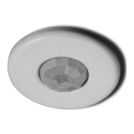
CS Series
360° PIR Occupancy Sensor
Specifications
Voltages . . . . . . . . . . . . . . . . . . . . .20–30VDC (24VDC Typical)
Current Consumption . . . . . . . . . . .@24VDC, 11mA Maximum
Time Adjustment . . . . . . . . . . . . . . . . .15 seconds–30 minutes
Sensitivity Adjustment . . . . . . . . . . . . . . .Minimum/Maximum
U.S. Patents:
4,757,204 • 4,787,722
Des360,842
Syracuse, NY 13221
800.223.4185
Advertisement
Table of Contents

Related Manuals for pass & seymour CS500


Summary of Contents for pass & seymour CS500
- Page 1 CS Series 360° PIR Occupancy Sensor Specifications Voltages .....20–30VDC (24VDC Typical) Current Consumption ...@24VDC, 11mA Maximum Time Adjustment .
-
Page 2: Coverage Patterns
12 feet from the sensor when mounted at 8 feet. Coverage shown in the diagrams below is maximum and represents coverage for half-step, walking motion, with no barriers or obstacles. DRAWING NOT TO SCALE High Density/Reduced Range Lens CS500 24 ft 8 ft Typical desk-top... - Page 3 PLACEMENT The effective coverage distances may be slightly less than the maximum sensing distance (see Coverage Patterns), depending upon obstacles such as furniture or partitions, and this must be considered when planning the number of sensors and their positioning. See the list below for approximate coverage distances for different types of motion.
-
Page 4: Installation
INSTALLATION CAUTION TURN POWER OFF AT CIRCUIT BREAKER BEFORE INSTALLING SENSOR A 4-S junction box can be used with a 3" mud-ring when local building codes mandate that low voltage connections be contained in a junction box. Otherwise a 3" mud-ring or the provided ceiling attachment ring can be used. IMPORTANT: If the lens will be masked, the junction box or mud-ring may need to be positioned so that the mask is oriented properly when the sensor is installed (see Masking). -
Page 5: Wiring Directions
MASKING An insert (mask) is supplied to allow elimination of coverage in unwanted areas. The mask is cut as needed and mounted onto anchor pins in the sensor’s cover. IMPORTANT: Do not use the mask if full coverage is desired. IMPORTANT: Before securing the sensor in the mounting location, the assembled sensor must be turned so the unmasked portion of the lens faces the coverage area (the blue masked area is visible through the lens). -
Page 6: Sensor Adjustment
SENSOR ADJUSTMENT The sensor comes factory preset and ready for operation. If testing of operation is desired: • Remove the sensor’s cover (twist). • Refer to the DIP switch settings chart below for switch configurations. • Make sure that office furniture and fixtures are in place. 1. -
Page 7: Troubleshooting
TROUBLESHOOTING CAUTION USE PROPER SAFETY PRECAUTIONS WHEN WORKING WITH OR NEAR HIGH VOLTAGE Lights will not turn on: 1. Verify the lens is not masked in the direction being tested (see Masking). 2. Adjust Sensitivity settings up if needed (DIP switches #7 & 8). 3. -
Page 8: Ordering Information
ORDERING INFORMATION Catalog# Description CS500 20–30VDC Occupancy Sensor with High Density/Reduced Range Lens CS1200 20–30VDC Occupancy Sensor with Extended Range Lens (Standard) PWP2120 Power Pack: 120VAC, 60Hz, 150mA 20A ballast/13A incandescent PWP2277 Power Pack: 277VAC, 60Hz, 150mA, 20A ballast AR120/277...
Need help?
Do you have a question about the CS500 and is the answer not in the manual?
Questions and answers