Table of Contents
Advertisement
Quick Links
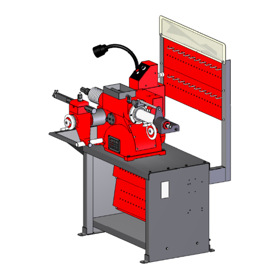
C9350C/C9370C Drum&Disc Brake Lathes
READ these instructions before placing unit in service.KEEP these and other
materials delivered with the unit in a binder near the machine for ease of
reference by supervisors and operators.
Handbook
Installation Instructions
Operating Instructions
Safety Instructions
Maintenance Instructions
SHENYANG 245 FACTORY
1
Advertisement
Table of Contents

Summary of Contents for Shenyang 245 Factory C9350C
- Page 1 C9350C/C9370C Drum&Disc Brake Lathes Handbook Installation Instructions Operating Instructions Safety Instructions Maintenance Instructions READ these instructions before placing unit in service.KEEP these and other materials delivered with the unit in a binder near the machine for ease of reference by supervisors and operators....
-
Page 2: Table Of Contents
Table of Contents Definitions of Hazard Levels……………………………………………3 User ’s Responsibility……………………………………………………4 Safety Notices and Decals………………………………………………5 Warning………………………………………………………………………5 Cautions and Dangers……………………………………………………6 Important Safety Instructions……………………………………………6 Before You Begin Receiving……………………………………………………………………8 Electrical Requirements……………………………………………………9 Installation …………………………………………………………………9 Operating Specifications …………………………………………………11 Principle Operating parts…………………………………………………12 Arbor Installation……………………………………………………………12 Chang and Choose Arbor…………………………………………………13 Adapters……………………………………………………………………13 Basic operation Spindle………………………………………………………………………14... -
Page 3: Definitions Of Hazard Levels
Reconditioning Brake Drums Preparation…………………………………………………………………16 Mounting Drums……………………………………………………………17 Reconditioning Disc Brake Rotors Preparation…………………………………………………………………20 Twin Cutters…………………………………………………………………21 Rotor Mounting………………………………………………………………21 Set Up and Reconditioning Rotors…………………………………………22 Typical Adapter Usage for Rotors…………………………………………25 Adapter Usage for Drums……………………………………………………25 Cross Feed Extension Installation Instructions…………………………25 Maintenance and Service Oiling……………………………………………………………………………26 Cleaning………………………………………………………………………27 Care of Arbors and Adapters………………………………………………27 Important Information Regarding Operation Safety and Eye and Face Protection………………………………………………………………………28 Definitions of Hazard Levels... -
Page 4: User's Responsibility
WARNING Watch for this symbol: △ ! WARNING It Means: Hazards or unsafe practices, which could result in severe personal Injury or death. CAUTION Watch for this symbol: △ ! CAUTION It Means: Hazards or unsafe practices, which may result in minor personal injury or product or property damage. -
Page 5: Safety Notices And Decals
9 If ownership of the unit is transferred, provide new user all information, manuals. Safety Notices and Decals For your safety, and the safety of others, read and understand all of the safety notices and decals included here and on the unit Read entire manual before installing, operating, or servicing this equipment. -
Page 6: Cautions And Dangers
a service facility , the unit should be in a room or enclosure provided for the purpose, or should be at least 18 " or more above floor to minimize the risk of igniting fuel vapors. Cautions and Dangers 1 Eye and face protection requirements: “Protective eye and face equipment is required to be used. - Page 7 When using equipment, basic safety precautions should always be followed, including the following: 1. Keep guards in place. 2. Remove adjusting keys and wrenches from the tool before turning it on. Make this a habit. 3. Keep work area clean. Cluttered areas and benches invite accidents. 4.
-
Page 8: Before You Begin
15. Avoid unintentional starting. Make sure the switch is in the OFF (O) position before plugging the machine in or performing any maintenance or service work. 16. Use recommended accessories. Consult the manufacturer's catalogs for recommended accessories. Use of improper accessories may cause risk of injury to operator or bystanders. -
Page 9: Electrical Requirements
If any of the goods called for on this bill of lading are shorted or damaged, do not accept them until the carrier makes a notation on the freight bill of the shorted or damaged goods. Do this for your own protection. Notify the carrier at once if any hidden loss or damage is discovered after receipt and request the carrier to make an inspection. - Page 10 2. After assembly, the bench should be leveled and may be bolted down with bolts or Screws. 3. Unbolt the lathe from the shipping pallet. Lift the lathe onto the bench. 4. Bolt the lathe to the bench with the hardware provided. Tighten fasteners securely.
-
Page 11: Operating Specifications
5.9 inch (150mm) – C9370C Cross feed speed Infinitely variable 0 – 0.015"/r (0 – 0.4mm/r) Maximum brake rotor diameter 7 -- 17" (178 -- 432 mm) – C9350C 7 -- 18" (178 -- 457 mm) – C9370C Cross Feed... -
Page 12: Principle Operating Parts
Principle Operating Parts 1. Bench 2.Radiate Window 3.Cross Feed Lock Knob 4. Slide Shaft 5.Tool Holder Housing 6. Nut Assembly 7. Tool Holder Cover 8. Cross Feed Assembly 9. Tool Holder 10. Cutter for Turning Drum 11. Square Head Screw GB85-M8x25 12. Stud 13. -
Page 13: Chang And Choose Arbor
The witness marks must be carefully aligned when installing the arbor (Figure 3). 1. Locate the witness marks on the arbor and the spindle. Figure 3-Align witness marks during arbor installation 2. Insert the arbor into the spindle making sure the witness marks are aligned. -
Page 14: Basic Operation
Basic Operation To completely understand drum and rotor turning you must have knowledge of the lathe itself. Spindle The spindle is a motor driven shaft that turns the arbor upon which the brake drum or rotor is mounted. By turning the drum and holding a cutting tool against the inner braking surface, metal can be removed. -
Page 15: Cross Feed
1. Release the belt tension by moving the V-belt adjusting lever to the right (clockwise). 2. Move the belt to the pulley groove that will give the correct spindle speed for the cut to be taken. 3. Reapply tension to the V-belt by moving the adjusting lever back to the operating position. -
Page 16: Basic Operation Of Handwheels
Basic Operation of Handwheel Clockwise rotation of the spindle feed handwheel retracts the spindle in towards the lathe. Clockwise rotation of the cross feed handwheel moves the cutting tool in towards the lathe. Figure 9-Clockwise rotation of handwheel Counterclockwise rotation of the spindle feed handwheel extends the spindle out away from the lathe. -
Page 17: Mounting Drums
Note: most often, the discard diameter is cast into the brake drum, not the maximum machining diameter. 3. Inspect brake drum. do not attempt to machine a drum that is damaged or in poor condition. Mounting Drums 1. Loosen the boring bar clamp nut and push the boring bar all the way into the clamp. - Page 18 6. Turn the drum by hand to make sure that everything is clear. 7. Turn the lathe ON. 8. Advance the tool bit manually until it just contacts the drum surface momentarily and makes a scratch cut. Figure 14 - First scratch cut 9.
- Page 19 12. Turn the spindle feed handwheel 1/2 turn in either direction and make a second scratch cut. No change the drum diameter. Figure 16-Second scratch cut 13. Turn the lathe OFF. 14. Examine the scratch cuts. If the first and second cuts are opposite one another (180°apart), fix wrong, remove the drum from the arbor, check the mounting adapters and arbor for nicks, burrs, or chips, remount the drum , and repeat scratch cut process.
-
Page 20: Reconditioning Disc Brake Rotors
until the cutter move to the drum outside. Turn off the drum/rotor switch and spindle motor switch. 21. Spindle feed speed should be adjusted by feed timing potentiometer. High speed used to roughing cut, low speed used to finish cut. NOTE: Refer to rotor diameter to find spindle speed and feed speed. -
Page 21: Twin Cutters
Twin Cutters Twin cutters can cut two surfaces of disc. Figure 20 – fix twin cutters Rotor Mounting Review the descriptions of mounting a brake drum on page 6. The same directions apply when mounting a brake rotor. Spacers are used to fill out the arbor shaft so that the arbor nut can be tightened. -
Page 22: Set Up And Reconditioning Rotors
Set Up and Reconditioning Rotors 1. Install a silencer band on the mounted rotor. Stretch the band around the rotor and hook the metal loop over a lead weight. Figure 22 – Attach silencer band 2. Center the twin cutter to the rotor. The twin cutter should be approximately parallel to the lathe spindle. - Page 23 8. When the tool bits make contact, rotate each of the inner depth-of-cut collars to zero and back the tool bits away from the rotor. Figure 25 – Tool bit controls 9. Turn the cross feed handwheel until the tool bits are at mid-point of the rotor face.
- Page 24 Figure 28 – Second scratch cut 12. If the scratch cuts are side; the run out or wobble is caused by rotor condition. A centesimal meter may be used to compare rotor run out with manufacturer's specifications. 13. If the scratch cuts are opposite one another (180°), the rotor may not be properly mounted on the arbor.
-
Page 25: Typical Adapter Usage For Rotors
Typical Adapter Usage for Rotors Before you begin It is important in any machining operation that all adapters and mounting hardware, as well as disc to be machined, are clean and free of nicks. IMPORTANT: The flange plate must contact the flat portion of the disc, but must not contact the rotor anywhere around the outside radius. -
Page 26: Maintenance And Service
Referring to the illustration, remove the cross feed locking stud and clean all surfaces of chips. Mount the cross feed extension plate directly on the cross feed seat. Insert the locking stud (with nut and washer assembly)through the cross shelves joint cross feed extension. Hand tightens the stud using the knurled head. -
Page 27: Cleaning
Use a hand pump grease gun only when cross feed grease fitting. A high pressure gun can burst the lathe casting. Figure 34 – Cross feed grease fitting Grease the feed screw pole monthly. Locate the feed screw pole by pulling the protective boot back. -
Page 28: Important Information Regarding Operation Safety And Eye And Face Protection
Shenyang 245 factory, as manufacturer of drum and disc break lathes, provides a safety shield with each model C9350,C9350C,C9370,C9370C brake lathe to be used with the twin cutter.
Need help?
Do you have a question about the C9350C and is the answer not in the manual?
Questions and answers