Table of Contents
Advertisement
Quick Links
Advertisement
Table of Contents

Summary of Contents for Rialto Comfort Thermo Kit
- Page 1 Thermo Kit Installation guide...
-
Page 2: Safety Warnings
Safety warnings All hardware connections must be made by a person who is suitably qualified and aware of the risks associated with installation, observing minimum standards of safety, and with the equipment isolated from the power supply. The user assumes all liability and risk connected with the steps of installing, configuring and utilizing these products with the end in view of benefiting from the various functionalities they offer. -
Page 3: Compatibility Requirements
Overview is a system for the smart management of domestic heating, ialto heRmo easy to use, allowing you to adjust the temperature of many independent zones. manages the domestic heating both at home and from remote, ialto heRmo thanks to the “Rialto” App, available for Android/iOS smartphone and/or tablet. Compatibility requirements To instal R you need:... - Page 4 Necessary equipment for assembly 1 slotted screwdriver (preferably mains tester) 1 drill with 5 mm tip 1 philips screwdriver Electrical tape | 4 |...
-
Page 5: Package Contents
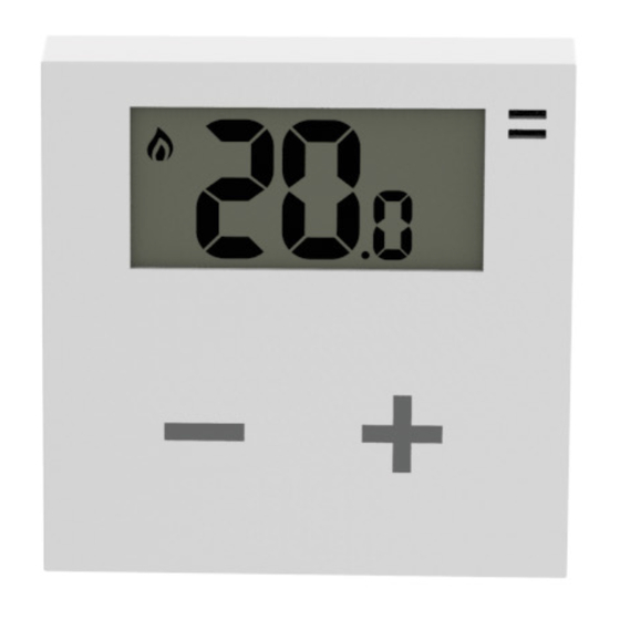
Package contents no. 1 R no. 1 R ialto heRmostat ialto hite no. 2 AA batteries no. 2 screws + no. 2 anchors no. 1 USB/micro USB cable no. 1 Ethernet cable no. 1 USB power supply no. 1 Installation guide | 5 |... - Page 6 ialto heRmostat Operating boiler Radio signal strength level Decrease/increase the temperature set-point No radio signal Temperature sensor Battery level | 6 |...
- Page 7 ialto hite 5 6 7 Reset button Network radio signal t (ZigBee). heRmostat Blue LED on: W connected to the t Ethernet port hite heRmostat Micro USB input Blue flashing LED: search t signal. heRmostat App pairing button Ethernet connection to the local network. White LED on: W connected to the router.
-
Page 8: Installation
Installation connection hite heRmostat 1. Connect the W to the router with the hite Ethernet cable (fig. 1 A). 2. Supply the W with the USB cable and its hite power supply unit included in the packaging (fig. fig. 1 1 B). - Page 9 9. Verify the t 's radio signal coverage by heRmostat tapping on + and - touch keys: on the display will appear at least one visible bar (fig. 4). 10. Verify the radio signal coverage of the W hite the blue LED on the W shall be hite switched steady on, NOT blinking (fig.
- Page 10 Replacing your old thermostat CAUTION: before any intervention, make sure power is turned off. C NO 1. Remove the cover of your old thermostat. Caution: dangerous voltage parts 2. Take a picture of the wiring. fig. 6 3. Identify the control cables COM (Common Cable) and NO (Normally Open), with the help of labels and / or connection screens in your old thermostat (fig.
-
Page 11: Installation Verification
rupt the boiler power supply. Therefore, the position of NO and COM wires is not important. 7. Cover the terminals with the supplied protection cover. 8. Verify the correct position of the batteries (fig. 3 page 6) and set the t on the mounting heRmostat plate (fig. -
Page 12: Technical Specifications
Technical specifications ialto heRmostat Wireless thermostat with battery and display with touch technology Main features Electronic control device with installation / Frequency: ZigBee HA 1.2 Radio features / 2.4.4 GHz / Alkaline batteries (2x) AA 1.5V Power Supply / Battery life: >2 years min Control relay / Contacts NC/COM/NO 250V 5A Cos(Φ)=1 resistive charge / Regulation range: +30°C... - Page 13 ialto hite Main features Ethernet-ZigBee gateway to connect to the router No. max t supportati eRmostati Power supply 5 V=, 0.4 A, 2 W power supply provided Radio features Frequency: ZigBee HA 1.2 Status display No. 3 operating status LEDs / no.
- Page 14 Notes | 14 |...
- Page 15 | 15 |...
- Page 16 1999/5/CE. The declaration of conformity is available on the web page www.rialtocomfort.com is a brand of ASTREL GROUP +05N003011R1.4 Rialto Thermo Kit installation guide_EN ASTREL GROUP SRL Via Isonzo, 21/E 34070 Mossa (GO) Italy 15.10.2016...
Need help?
Do you have a question about the Thermo Kit and is the answer not in the manual?
Questions and answers