Daikin McQuay 910121754 Installation & Maintenance Data
Digitally adjustable display sensor for water source heat pumps smartsource gs series; smartsource gt series; with microtech iii controls enfinity cch series; enfinity ccw series; enfinity vfc series; enfinity vfw series; enfinity lvc series; enfinity lvw
Table of Contents
Advertisement
Digitally Adjustable Display Sensor
Used With:
Water Source Heat Pumps (WSHP) - Sensor Part No. 910121754
SmartSource™ Units - Models GS & GT
Enfinity™ Units with MicroTech
MHC, MHW & VHC, VHF
Fan Coil Units (FCU) - Sensor Part No. 910113679
Models With MicroTech III Controls
©2013 McQuay International
Installation & Maintenance Data
®
III Controls - Models CCH, CCW; VFC, VFW; LVC, LVW;
•
800.432.1342
•
www.mcquay.com
IM 1171-3
Group: WSHP/FCU
Part Number: 910140464
Date: January 2013
Advertisement
Table of Contents

Summary of Contents for Daikin McQuay 910121754
- Page 1 Part Number: 910140464 Date: January 2013 Digitally Adjustable Display Sensor Used With: Water Source Heat Pumps (WSHP) - Sensor Part No. 910121754 SmartSource™ Units - Models GS & GT Enfinity™ Units with MicroTech ® III Controls - Models CCH, CCW; VFC, VFW; LVC, LVW;...
-
Page 2: Table Of Contents
Sensor Functions ..............5 Override & Alarm Reset): ..........10 910113679, Fan Coil Unit Model: ........5 Occupied Button (Occupied/ ..........910121754, Water Source Heat Pump Model: ....5 Unoccupied Request): ...........10 Up & Down Setpoint Buttons ..........Sensor Dimensions .............5 (Temp Or Humidity): ............11 Terminations ................6... -
Page 3: Overview
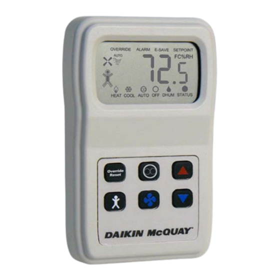
Overview The display sensor is used in conjunction with the MicroTech Figure 1: Digital display sensor - P/N 910121754, Fan Coil III equipped units as described in the Application Section P/N 910113679 below. The same sensor is used for Water Source Heat Pump (WSHP) and for Fan Coil Units (FCU) with just a hardware jumper and menu change during configuration. -
Page 4: Applications
Console Heat Pumps W. GSH, GSV SmartSource 1-Stage Horizontal & MicroTech III SmartSource W. GTH, GTV Vertical Unit Controller SmartSource 2-Stage Daikin McQuay Inverter W. DFW Vertical SmartSource Inverter Controller FC.H, FH.H Fan Coils Horizontal ThinLine™ MicroTech III Unit Controller... -
Page 5: Sensor Functions
2.784 4.500 Termination Daikin McQuay recommends using a twisted shielded pair of at least 22AWG for the power wire connections. The shield should be earth grounded only at the power source. Larger gauge wire may be required for long runs. -
Page 6: Terminations
3 (SP) 4 (UTS) 5 (GND) 6 (FC) Description Sensor Digitally Adjustable Room Temperature Sensor (Part No. 910121754) Figure 5: Fan-Coil MicroTech III board to digital room temperature sensor wiring MicroTech III Board SmartSource Board Base Board Terminal Block Label... -
Page 7: Mounting
Mounting Location 7. Screw the plate firmly to the wall so the foam plate Avoid mounting on outside walls or in direct sunlight. backing is compressed about 50%. Junction Box, (J-Box) 8. Terminate the unit according to the guidelines in the 1. -
Page 8: Initial Start-Up Occupied Sequence
Setpoint Analog Range Tolerance Table 3: Setpoint analog range tolerance Adjusting The Setpoint (Temperature or Setpoint Analog Tolerance Humidity) 55° to 95°F Scale -5° to +5°F Scale Terminal 3 Analog Output Whichever is displayed at the time, temperature or humidity: @ 55°F (min.) @ -5°F (min.) 0.0 to 0.10 vdc... -
Page 9: Fan Status & Speed Indicators
Display Descriptions Fan Status & Speed Indicators: Table 4: WSHP unit status input timing definition The Fan Shape, 4 Wavy Lines and “Auto” word Status Dot Status Dot "ON" WSHP Display indicate Fan and Speed status. "OFF" (0 vdc) (+ 5 vdc) time Availability Indication Time... -
Page 10: Front Panel Button Operation
Front Panel Button Operation • System Mode Indication (FCU Only) “Off” on the display means the unit will not provide cooling, heating, dehumidification or fan operation (“E” “Heat/Cool/Auto/Off” terminal goes Low). The “Heat/Cool/Auto/Off” Mode Indicators on the bottom • “Dhum” on the display means that only dehumidification of the display show the mode status of the sensor and are will operate. -
Page 11: Up & Down Setpoint Buttons
The humidity setpoint is always between 40% to 90%. After 5 seconds of no buttons being pushed, the sensor will go into as FCU). 910121754 = Jumper installed for the standard display mode. WSHP (Default for units ordered System Mode Button (FCU Has as WSHP). - Page 12 Optional Technician Adjustments FCU Models Locks fan to the Fan Low speed Note: If P1 is changed, then P4 and P5 must be changed to position (No Sensor Fan button control) set desired setpoint values. FCU Models Locks fan to the Fan Off position Temperature Offset (Factory set to zero).
- Page 13 Optional Technician Adjustments Firmware Version - XXX.X 9 = Humidity Setpoint (HSP). P15 For Units with a BACnet or LonWorks 10 = Temperature Value & Humidity Setpoint. Communications Module 11 = Temperature Setpoint & Humidity Setpoint. Setpoint Calibration Offset (Factory set to “0”.) 12 = Temperature Value & Temp Setpoint & Humidity •...
-
Page 14: Diagnostics
Diagnostics Problem & Possible Solution Occupied Not Working • Verify that this terminal is in a powered circuit. Measure No Display • Check the power connections and power voltage level the voltage to ground at the occupied terminal (U). When pushing the Occupied Button (<2 secs), it should read •... -
Page 15: Specifications
Specifications Supply Voltage: Field Setup Jumper J50: AC Hot ..... (R) 7 to 28VAC, 24VAC nominal, 0.17VA PRG ......Program Mode, On = Program, Off = Run. GND/Neutral ...(5) Sensor common reference ground. F/C......Display Units, On = ºC, Off = ºF. MDL ......MODEL, On = WSHP. - Page 16 Now that you have made an investment in modern, efficient Daikin McQuay equipment, its care should be a high priority. For training information on all Daikin McQuay HVAC products, please visit us at www.daikinmcquay.com and click on Training, or call 540-248-9646 and ask for the Training Department.
Need help?
Do you have a question about the 910121754 and is the answer not in the manual?
Questions and answers