
Subscribe to Our Youtube Channel
Summary of Contents for Bewator Visilynx 3 Series
- Page 1 Visilynx 3 Series Matrix Switcher VisiPC Software Version 2.01 Part 1 – Visilynx 3 Configurator USER MANUAL Manual : INS00231 Issue 4...
-
Page 2: Table Of Contents
VisiPC Software Manual Part 1 – Visilynx 3 Configurator Table Of Contents INTRODUCTION..........................3 1.1 P ......................4 RINCIPLES PERATION GETTING STARTED ........................5 2.1 H – RS232 I ..............5 ARDWARE NTERCONNECTION NTERFACE 2.2 M PC R ......................6 INIMUM EQUIREMENTS 2.3 S... -
Page 3: Introduction
511 fully functional cameras. A smaller special-purpose rack system is used for trainborne applications. All Visilynx 3 series matrix switcher systems are supplied with a CD-ROM package of configuration and test software called VisiPC, which should be installed onto a suitable PC. -
Page 4: Principles Of Operation
VisiPC Software Manual Part 1 – Visilynx 3 Configurator 1.1 Principles Of Operation VisiPC's main principles of operation are: • A PC COM port is chosen at the ‘Options/Comm. Port’ menu. • The PC port is connected to the Visilynx 3 system ‘test and config’ port using an RS-232 cable. -
Page 5: Getting Started
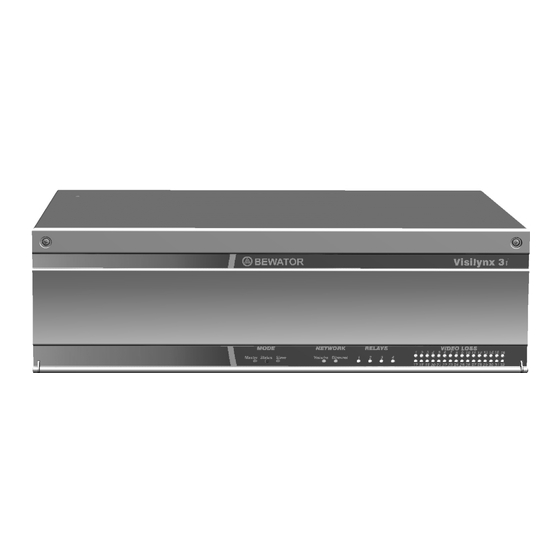
The V3i System Unit incorporates an RS232 Test/Config connector port on the rear panel which allows connection, via a supplied 9-way to 9-way interface lead (Bewator Ltd. Part Number VC-3CONFIG), to an external PC for system set-up and testing. Please refer to Figure 2. -
Page 6: Minimum Pc Requirements
VisiPC Software Manual Part 1 – Visilynx 3 Configurator 2.2 Minimum PC Requirements ® • Windows 95, 98, NT, 2000, XP • 64Mb RAM ® • Pentium 233MHz • One serial port • 10Mb of hard disk space • CD-ROM drive Warning: If the PC is slower than listed above, or if it is fitted with a network card that is not connected to a live network, then communications errors may occur when transferring new software to a Visilynx 3 system. - Page 7 VisiPC Software Manual Part 1 – Visilynx 3 Configurator Figure 3 Visilynx 3 Configurator Global System Settings 2.4.1 Status Bar A status bar along the bottom of the screen displays various information on the configuration or communication status in five panes. The leftmost pane indicates the selected product, either ‘Modular’...
- Page 8 VisiPC Software Manual Part 1 – Visilynx 3 Configurator Whenever VisiPC is communicating with a V3 system, (e.g. during configuration transfer) the first three panes of the status bar change to one pane. This leftmost pane then indicates the status of the communications: Colour Description Indication...
-
Page 9: Menu Bar
VisiPC Software Manual Part 1 – Visilynx 3 Configurator 3 MENU BAR The menu bar provides access to the menu commands in the normal Microsoft Windows fashion. 3.1 File Menu Commands Figure 4 File Menu Click Create a new ‘default’ configuration set-up. - Page 10 VisiPC Software Manual Part 1 – Visilynx 3 Configurator Figure 5 Visilynx Defaults Warning 3.1.2 Open… Command Shortcut keys: Ctrl-O, Alt-FO Toolbar: Use this command to open an existing configuration set-up. This will overwrite your currently open configuration set-up. Figure 6 'File Open' Dialog Box The dialog box allows you to select a previously saved configuration file for use (in this case from a choice of just three).
- Page 11 VisiPC Software Manual Part 1 – Visilynx 3 Configurator Use this command to save the current configuration to its current name and directory. When you save a document for the first time, Visilynx 3 configuration displays the ‘Save As…’ Dialog Box so you can name your document. If you want to change the name and directory of an existing document before you save it, choose the ‘Save As…’...
- Page 12 VisiPC Software Manual Part 1 – Visilynx 3 Configurator Figure 8 Import Dialog Box 3.1.6 View Log Command Shortcut keys: Alt-FV Toolbar: The log records all of the errors found during loading or validating a particular configuration and lists them for reference, as shown above. The system will log all errors made as they happen.
-
Page 13: Node Menu Commands
VisiPC Software Manual Part 1 – Visilynx 3 Configurator Figure 9 VisiPC Log Window 3.1.7 Exit Command Shortcut keys: Alt-F4 Use this command to close VisiPC. 3.2 Node Menu Commands Figure 10 Node Menu Note: Node menu commands are not currently implemented by Visilynx 3 software. warning is provided. - Page 14 VisiPC Software Manual Part 1 – Visilynx 3 Configurator Figure 11 Transfer Menu Use the ‘Configuration’ ‘Send’ and ‘Receive’ commands to send or receive a file to or from the system. 3.3.1 Transfer Configuration Send Command Shortcut keys: Alt-TCS Toolbar: ‘Send’...
- Page 15 VisiPC Software Manual Part 1 – Visilynx 3 Configurator 3.3.2 Transfer Configuration Receive Command Shortcut keys: Alt-TCR Toolbar: ‘Receive’ is used to collect a configuration from the Visilynx 3 system, for backup purposes. It is highly recommended that the received configuration should be saved to disk before making any changes.
- Page 16 VisiPC Software Manual Part 1 – Visilynx 3 Configurator The ‘Open Software File’ option is used to select the software to be transferred to the FLASH memory in the Visilynx 3 CPU. Once the file has been selected, click the Open button and the transfer process will begin V3i software is distributed in these files;...
-
Page 17: Switch Menu Commands
VisiPC Software Manual Part 1 – Visilynx 3 Configurator 3.3.5 Transfer Date/Time… Command Shortcut keys: Alt-TD Selecting the Transfer/Date/Time… menu brings up the ‘Date and Time’ dialog. Figure 17 Date and Time Dialog Box The ‘Date and Time’ option allows you to set the date and time for the Visilynx 3 system as a whole. -
Page 18: Options Menu Commands
VisiPC Software Manual Part 1 – Visilynx 3 Configurator 3.4.3 Receiver Configurator Command Shortcut keys: Alt-SC Select this option to switch to the RX3 Receiver Configurator sub-program. VisiPC will disappear for a few seconds while the RX3 Receiver Configurator screen loads (see page 86). - Page 19 VisiPC Software Manual Part 1 – Visilynx 3 Configurator The ‘Mode’ selector selects whether the VisiPC program is acting as a Master, Slave or both. For most purposes, ‘Master’ Mode should be selected. The ‘Port’ and the ‘Baud’ rate are selected independently for both the Master and the Slave ports, as required.
-
Page 20: Help Menu Commands
VisiPC Software Manual Part 1 – Visilynx 3 Configurator Figure 22 Activity Log Window The window opens immediately below the main VisiPC Window. The size and position of the window can be changed by the user. The ‘Activity log’ can be copied by clicking on the Activity Log window and then pressing Ctrl-C. -
Page 21: System Settings
VisiPC Software Manual Part 1 – Visilynx 3 Configurator 4 SYSTEM SETTINGS 4.1 Introduction The system settings are the building blocks for each configuration. ‘Global System Settings’ are adjusted to accurately reflect the installed equipment. Once configured and accepted, the individual system parts will appear in the ‘Settings’ tree menu on the left-hand side of the screen, with the total number of each installed component appearing in brackets. -
Page 22: Global System Settings
VisiPC Software Manual Part 1 – Visilynx 3 Configurator 4.3 Global System Settings When the VisiPC software is first installed, or when a new configuration is created using ‘File/New’, factory default values will appear for all of the ‘Global System Settings’, as shown below. - Page 23 VisiPC Software Manual Part 1 – Visilynx 3 Configurator The Product selector is provided to select ‘Modular’ or ‘Integrated’, which affects various maximum values and some defaults throughout the configuration screens (see Table 3). If a value is reduced to zero, the feature is assumed not to be installed, and will not be displayed in the settings menu on the left-hand side.
-
Page 24: Alarm Settings
VisiPC Software Manual Part 1 – Visilynx 3 Configurator is detected, the system will show you an error message saying, for example, ‘Configuration verification found 6 error(s)! See log file’. The error log is updated each time an error occurs. Now proceed to the individual component parts of the configuration, starting with the Alarm Settings menu detailed below. - Page 25 VisiPC Software Manual Part 1 – Visilynx 3 Configurator • Description: Each alarm can be given a name, up to 16 characters long, e.g. ‘Front Entrance’. It can be labelled as anything you want, but should reflect the alarm position or type in some way.
- Page 26 VisiPC Software Manual Part 1 – Visilynx 3 Configurator • Restore: will return all of the settings for the current page to the point when the configuration was last saved using Accept. • Default: will restore the settings to valid default values for the current page. 4.4.1 Alarm Keyboard Access Settings ‘Alarm Keyboard Access Settings’...
-
Page 27: Camera Settings
VisiPC Software Manual Part 1 – Visilynx 3 Configurator • Default: will restore the settings to valid default values for the current page. 4.5 Camera Settings ‘Camera Settings’ allows you to set up each camera on the system. The tree on the left highlights ‘Camera’... - Page 28 VisiPC Software Manual Part 1 – Visilynx 3 Configurator cameras 62, 63 and 64. Now these cameras can be accessed as 6 to 12, without changing existing camera input connections. • Picture Loss Alarm: • Enable: Tick the box to activate. This alarm will be in addition to the sync. loss alarm which is always present.
- Page 29 VisiPC Software Manual Part 1 – Visilynx 3 Configurator 4.5.1 Camera Control User Access Settings ‘Camera Control User Access Settings’ assigns permission to each user who is allowed to control the selected camera (via telemetry). Telemetry controls various features of the camera, including pan, tilt, zoom, presets, etc.
- Page 30 VisiPC Software Manual Part 1 – Visilynx 3 Configurator 4.5.2 Camera View User Access Settings ‘Camera View User Access Settings’ assigns permission to each user who is allowed to view the selected camera. This is the same list as is configured by the ‘User Camera View Access Settings’ screen (see page 73), but arranged by camera number rather than user number.
-
Page 31: Keyboard
VisiPC Software Manual Part 1 – Visilynx 3 Configurator 4.6 Communication Channel Settings ‘Communication Channel Settings’ allows you to set up each communication channel on the system. The tree on the left highlights ‘Comm. channel’ and shows the total number of channels configured for the system in brackets. - Page 32 VisiPC Software Manual Part 1 – Visilynx 3 Configurator Network Option card (Master unit) RS-232 14-15 Port not present Port disabled Serial Port (Slave unit) RS-232 + RS-485 Port disabled PCCON (Slave unit) RS-232 + RS-485 Port disabled Serial Port (Slave unit) RS-232 + RS-485 Port disabled Serial Port (Slave unit)
- Page 33 • Parity: choose ‘None’, ‘Odd’, or ‘Even’, according to the protocol of the connected device. Note: Bewator (Molynx Videmech) cameras and keyboards use even parity. • Data Bits: choose 7 or 8 data bits, according to the protocol of the connected device.
- Page 34 VisiPC Software Manual Part 1 – Visilynx 3 Configurator to prevent unauthorised use. The timeout (measured in seconds) begins after the last key selection or joystick movement at the keyboard. The timeout period may be set between 1 and 255 seconds. •...
- Page 35 VisiPC Software Manual Part 1 – Visilynx 3 Configurator 4.7.1 Keyboard Alarm Access ‘Keyboard Alarm Access Settings’ assigns to the selected keyboard permission to manage and view each alarm. If the same alarm is configured as both a Keyboard Alarm and a System Alarm (see page 63), only the System Alarm Setting will be used by the Visilynx 3 system.
- Page 36 VisiPC Software Manual Part 1 – Visilynx 3 Configurator 4.7.2 Keyboard Monitor Access Settings ‘Keyboard Monitor Access Settings’ assigns to the selected keyboard permission to control each monitor. Reference should be made to an installation plan to establish a logical approach for monitor access.
- Page 37 VisiPC Software Manual Part 1 – Visilynx 3 Configurator 4.7.3 Keyboard Node Alarm Access ‘Keyboard Node Alarm Access Settings’ assigns to the selected keyboard permission to manage and view alarms on each network node. This is the same list as is configured by the ‘Node Alarm Keyboard Access Settings’ screen (see page 52), but arranged by keyboard number rather than node number.
- Page 38 VisiPC Software Manual Part 1 – Visilynx 3 Configurator 4.7.4 Keyboard Quad Access Settings ‘Keyboard Quad Card Access Settings’ assigns to the selected keyboard permission to control each quad card. Reference should be made to an installation plan to establish a logical approach for quad access, i.e.
-
Page 39: Monitor Settings
VisiPC Software Manual Part 1 – Visilynx 3 Configurator 4.8 Monitor Settings ‘Monitor Settings’ allows you to set up each video monitor on the system. The tree on the left highlights ‘Monitor’ and shows the total number of monitors configured for the system in brackets. - Page 40 VisiPC Software Manual Part 1 – Visilynx 3 Configurator 4.8.1 Monitor Alarm Text ‘Monitor Alarm Text’ allows you to enable and position the text which appears on the selected monitor (if it is configured as a keyboard or system alarm monitor) during an alarm condition.
- Page 41 VisiPC Software Manual Part 1 – Visilynx 3 Configurator 4.8.2 Monitor Camera Text ‘Monitor Camera Text’ allows you to enable and position the text which appears on the selected monitor when a camera is selected. The screen operates in the same way as ‘Monitor Alarm Text’...
- Page 42 VisiPC Software Manual Part 1 – Visilynx 3 Configurator 4.8.3 Monitor Default Camera Settings ‘Monitor Default Camera Settings’ allows you to assign different default camera numbers to the selected monitor, when camera mapping is enabled. This will only appear if you have defined one or more camera maps in the ‘Global System Settings’...
- Page 43 VisiPC Software Manual Part 1 – Visilynx 3 Configurator • Default: will restore the settings to valid default values for the current page. 4.8.4 Monitor Keyboard Access Settings ‘Monitor Keyboard Access Settings’ assigns permission to each keyboard that is allowed to control the selected monitor.
- Page 44 VisiPC Software Manual Part 1 – Visilynx 3 Configurator 4.8.5 Monitor Time Text ‘Monitor Time Text’ allows you to enable and position the on-screen time and date display. The screen operates in the same way as ‘Monitor Alarm Text’, detailed on page 40. Figure 43 Monitor Time Text Screenshot •...
- Page 45 VisiPC Software Manual Part 1 – Visilynx 3 Configurator 4.8.6 Monitor User Access Settings ‘Monitor User Access Settings’ assigns permission to each user who is allowed to control the selected monitor. Reference should be made to an installation plan to establish a logical approach to monitor access.
- Page 46 VisiPC Software Manual Part 1 – Visilynx 3 Configurator 4.8.7 Monitor User Text ‘Monitor User Text’ is only visible for V3M systems and allows you to enable and position the on-screen user definable text. The screen operates in the same way as ‘Monitor Alarm Text’ detailed on page 40.
- Page 47 VisiPC Software Manual Part 1 – Visilynx 3 Configurator 4.8.8 Monitor View Text ‘Monitor View Text’ allows you to enable and position the text which appears on the selected monitor when a view is selected. The screen operates in the same way as ‘Monitor Alarm Text’...
-
Page 48: Multiplexer Settings
VisiPC Software Manual Part 1 – Visilynx 3 Configurator 4.9 Multiplexer Settings ‘Multiplexer Settings’ allows you to configure a timeout delay for each multiplexer connected to the system. Figure 47 Multiplexer Settings Screenshot • Use the Multiplexer selector (bottom right) to select the one to configure. •... - Page 49 VisiPC Software Manual Part 1 – Visilynx 3 Configurator 4.9.1 Multiplexer User Access Settings ‘Multiplexer User Access Settings’ assigns permission to each user who is allowed to control the selected multiplexer. This is the same list as is configured by the ‘User Multiplexer Access Settings’ screen (see page 75), but arranged by multiplexer number rather than user number.
-
Page 50: Node Settings
VisiPC Software Manual Part 1 – Visilynx 3 Configurator 4.10 Node Settings ‘Node Settings’ allows you to configure the operating parameters for each connected Node. Figure 49 Node Settings Screenshot • Name: Type in a preferred name for your local node, up to 16 characters long. •... - Page 51 VisiPC Software Manual Part 1 – Visilynx 3 Configurator • Monitor Texts: allows you to configure the text that appears on all monitors that are viewing network cameras, during these conditions: • Trunk Stolen: The trunk carrying the camera signal has been stolen. •...
- Page 52 VisiPC Software Manual Part 1 – Visilynx 3 Configurator 4.10.1 Node Alarm Keyboard Access Settings ‘Node Alarm Keyboard Access Settings’ assigns permission to each keyboard that is allowed to manage and view alarms on the selected network node. A Visilynx 3 system can consist of up to 127 separate nodes. Each node can generate up to 1701 alarms.
-
Page 53: Node Trunk Settings
VisiPC Software Manual Part 1 – Visilynx 3 Configurator • Default: will restore the settings to valid default values for the current page. 4.11 Node Trunk Settings ‘Node Trunk Settings’ allows you to configure the camera inputs and monitor outputs that form the trunks that connect nodes. -
Page 54: Quad Card Settings
VisiPC Software Manual Part 1 – Visilynx 3 Configurator 4.12 Quad Card Settings Cameras can be assigned to each of the Quad cards fitted in the system (up to 4 (optional) for V3i and 32 for V3M). Note: In a V3i system, text is shown above the ‘Quad card’ selector to identify the V3i unit and the rear panel connector used for the selected Quad card video output: •... - Page 55 VisiPC Software Manual Part 1 – Visilynx 3 Configurator • When the system is reset using the pushbutton either on the back panel of a V3i unit or on the CPU card of a V3M system. • When the system is switched on for the first time after loading a new configuration. Note: For V3M systems only, a second camera map ‘Map 2’...
- Page 56 VisiPC Software Manual Part 1 – Visilynx 3 Configurator 4.12.1 Quad Card Keyboard Access Settings ‘Quad Card Keyboard Access Settings’ assigns permission to each keyboard that is allowed to control the selected quad card. Reference should be made to an installation plan to establish a logical approach for keyboard access, e.g.
- Page 57 VisiPC Software Manual Part 1 – Visilynx 3 Configurator 4.12.2 Quad Card User Access Settings ‘Quad Card User Access Settings’ assigns permission to each user who is allowed to control the selected quad card. This is the same list as is configured by the ‘User Quad Card Access Settings’ screen (see page 76), but arranged by quad card number rather than user number.
-
Page 58: Relay Settings
VisiPC Software Manual Part 1 – Visilynx 3 Configurator 4.13 Relay Settings ‘Relay Settings’ allows you to configure the action of each relay connected to the system. Figure 55 Relay Settings Screenshot • Use the Relay selector (bottom right) to select the one to configure. •... - Page 59 VisiPC Software Manual Part 1 – Visilynx 3 Configurator 4.13.1 Relay User Access Settings ‘Relay User Access Settings’ assigns permission to each user who is allowed to view the selected relay. This is the same list as is configured by the ‘User Relay Access Settings’ screen (see page 77), but arranged by relay number rather than user number.
-
Page 60: Sequence Settings
VisiPC Software Manual Part 1 – Visilynx 3 Configurator 4.14 Sequence Settings ‘Sequence Settings’ allows you to configure sequences of cameras or views to be shown at when required. Up to 64 sequences may be selected. Each configured sequence provides from 2 to 63 steps. When a sequence step is selected, the step number is highlighted, as shown below at Step 1. - Page 61 VisiPC Software Manual Part 1 – Visilynx 3 Configurator • Delete: removes the highlighted step. • Accept: will save the settings for the current page. • Restore: will return all of the settings for the current page to the point when the configuration was last saved using Accept.
-
Page 62: System Settings
VisiPC Software Manual Part 1 – Visilynx 3 Configurator 4.15 System Settings ‘System Settings’ allows you to set parameters for the system as a whole and to define system alarm monitors. When an alarm is marked as a System Alarm, it is displayed on system alarm monitors instead of keyboard alarm monitors, and it does not need accepting or cancelling by a keyboard. - Page 63 VisiPC Software Manual Part 1 – Visilynx 3 Configurator • Alarm Handling: Determines how system alarms are managed. • LIFO (last in, first out), meaning the most recent alarm is handled first, and FIFO (first in, first out), meaning the oldest alarm is handled first, are the two options available for alarm management.
- Page 64 VisiPC Software Manual Part 1 – Visilynx 3 Configurator 4.15.1 System Alarm Access Settings ‘System Alarm Access Settings’ configures each alarm which is to be treated as a system alarm. • System alarms are handled using System Settings. • Non-system alarms are handled using Keyboard Settings. If the same alarm is configured as both a Keyboard Alarm (see page 35) and a System Alarm, only the System Alarm Setting will by used by the Visilynx 3 system.
-
Page 65: Telemetry Card Settings
VisiPC Software Manual Part 1 – Visilynx 3 Configurator 4.16 Telemetry Card Settings ‘Telemetry Card Settings’ allows each connected Telemetry card to be configured. For V3i, each unit has the equivalent of two D-Type Telemetry cards, so a Master and Slave unit together can be connected to up to 64 cameras (each telemetry port can be connected to only one camera). - Page 66 • Parity: choose ‘None’, ‘Odd’, or ‘Even’, according to the protocol of the connected device. Note: Bewator (Molynx Videmech) cameras use even parity. • Data Bits: choose 7 or 8 data bits, according to the protocol of the connected deviceAt present only 8 data bits are supported, in accordance with the Molynx protocols.
- Page 67 VisiPC Software Manual Part 1 – Visilynx 3 Configurator Figure 61 Telemetry Card Cameras Screenshot ~ V3i Figure 62 Telemetry Card Cameras Screenshot ~ V3M INS00231 Issue 4 Page 67 of 88...
- Page 68 VisiPC Software Manual Part 1 – Visilynx 3 Configurator • Use the Telemetry card selector (bottom right) to select the one to configure. • C-Type (V3i only): ‘Off’ disables the C-type telemetry function for the camera corresponding to that port. ‘On’...
-
Page 69: Timed Event Settings
VisiPC Software Manual Part 1 – Visilynx 3 Configurator 4.17 Timed Event Settings ‘Timed Event Settings’ configures timed actions which enables Visilynx 3 to issue a variety of commands automatically during a seven day period; rather like setting up a domestic VCR to record future television programmes. - Page 70 VisiPC Software Manual Part 1 – Visilynx 3 Configurator • ‘Enable Alarms’: A range of alarms can be enabled as an event. First Alarm and Last Alarm boxes appear to enable the selection of a range of alarms, e.g. from 26 to 53 inclusive.
-
Page 71: User Settings
VisiPC Software Manual Part 1 – Visilynx 3 Configurator 4.18 User Settings ‘User Settings’ allows capabilities for each user to be set, in order to distinguish between each user on the system. Figure 64 User Settings Screenshot • Use the User selector (bottom right) to select the one to configure. •... - Page 72 VisiPC Software Manual Part 1 – Visilynx 3 Configurator 4.18.1 User Camera Control Access Settings ‘User Camera Control Access Settings’ assigns to the selected user permission to control each camera. This is the same list as is configured by the ‘Camera Control User Access Settings’ screen (see page 29), but arranged by user number rather than camera number.
- Page 73 VisiPC Software Manual Part 1 – Visilynx 3 Configurator 4.18.2 User Camera View Access Settings ‘User Camera View Access Settings’ assigns to the selected user permission to view each camera. This is the same list as is configured by the ‘Camera View User Access Settings’ screen (see page 30), but arranged by user number rather than camera number.
- Page 74 VisiPC Software Manual Part 1 – Visilynx 3 Configurator 4.18.3 User Monitor Access Settings ‘User Monitor Access Settings’ assigns to the selected user permission to control each monitor. This is the same list as is configured by the ‘Monitor User Access Settings’ screen (see page 45), but arranged by user number rather than monitor number.
- Page 75 VisiPC Software Manual Part 1 – Visilynx 3 Configurator 4.18.4 User Multiplexer Access Settings ‘User Multiplexer Access Settings’ assigns to the selected user permission to control each multiplexer. This is the same list as is configured by the ‘Multiplexer User Access Settings’ screen (see page 49), but arranged by user number rather than multiplexer number.
- Page 76 VisiPC Software Manual Part 1 – Visilynx 3 Configurator 4.18.5 User Quad Access Settings ‘User Quad Card Access Settings’ assigns to the selected user permission to control each quad card. This is the same list as is configured by the ‘Quad Card User Access Settings’ screen (see page 57), but arranged by user number rather than quad card number.
- Page 77 VisiPC Software Manual Part 1 – Visilynx 3 Configurator 4.18.6 User Relay Access Settings ‘User Relay Access Settings’ assigns to the selected user permission to control each relay. This is the same list as is configured by the ‘Relay User Access Settings’ screen (see page 59), but arranged by user number rather than relay number.
- Page 78 VisiPC Software Manual Part 1 – Visilynx 3 Configurator 4.18.7 User VCR/DVR Access Settings ‘User VCR/DVR Access Settings’ assigns to the selected user permission to control each VCR/DVR. This is the same list as is configured by the ‘VCR/DVR User Access Settings’ screen (see page 81), but arranged by User number rather than VCR/DVR number.
-
Page 79: Vcr/Dvr Settings
VisiPC Software Manual Part 1 – Visilynx 3 Configurator 4.19 VCR/DVR Settings ‘VCR/DVR Settings’ allows the configuration of the timeout for each DVR or VCR. Figure 72 VCR/DVR Settings Screenshot • Use the VCR/DVR selector (bottom right) to select the one to configure. •... - Page 80 VisiPC Software Manual Part 1 – Visilynx 3 Configurator 4.19.1 DVR Default Input Settings ‘DVR Default Input Settings’ maps the six physical DVR inputs to the six recording channels. Note: The settings on this screen are only used by a trainborne rack system to configure its internal DVR.
- Page 81 VisiPC Software Manual Part 1 – Visilynx 3 Configurator • Accept: will save the settings for the current page. • Restore: will return all of the settings for the current page to the point when the configuration was last saved using Accept. •...
-
Page 82: View Settings
VisiPC Software Manual Part 1 – Visilynx 3 Configurator • Restore: will return all of the settings for the current page to the point when the configuration was last saved using Accept. • Default: will restore the settings to valid default values for the current page. 4.20 View Settings ‘View Settings’... -
Page 83: Zone Settings
VisiPC Software Manual Part 1 – Visilynx 3 Configurator 4.21 Zone Settings ‘Zone Settings’ allows a zone, containing up to 31 camera-monitor pairs, to be defined. A ‘Zone’ is a view of a scene from various cameras spread across a set of monitors simultaneously. - Page 84 VisiPC Software Manual Part 1 – Visilynx 3 Configurator • Monitor: Each zone position inserted needs to be assigned to a unique monitor number. When a zone is called up, a maximum of 31 video images may be displayed on 31 separate monitors giving the user a comprehensive blanket view of a chosen area.
-
Page 85: Visilynx 3 Tester & Simulator
The VisiPC Visilynx 3 Tester & Simulator sub-program includes features for the function testing of V3 systems. A detailed description of the ‘Visilynx 3 Tester & Simulator’ software can be found in Part 2 of the manual (Bewator Limited document INS00237). INS00231 Issue 4 Page 85 of 88... -
Page 86: Receiver Tester & Simulator
VisiPC Software Manual Part 1 – Visilynx 3 Configurator 6 RECEIVER TESTER & SIMULATOR The ‘Receiver Tester & Simulator’ sub-program always loads with the ‘Status Log’ tab selected. Switching is performed from the Switch menu. Figure 78 Receiver Tester & Simulator Status Log Tab The VisiPC Receiver Tester &... -
Page 87: Receiver Configurator
The VisiPC Receiver Configurator sub-program will, in a future release, include features for the creation and editing of configuration files for RX3 receivers. The use of the ‘Receiver Configurator’ software is described in the RX3 Installation and Maintenance Manual (Bewator Limited document INS00271). INS00231 Issue 4 Page 87 of 88... -
Page 88: Notes
Albany Street, Newport, South Wales, United Kingdom, NP20 5XW. Telephone: +44 (0) 1633 821000, Fax: +44 (0) 1633 850893 Email: sales@bewator.co.uk : Internet: http://www.bewator.co.uk/ Customer Support Tel: +44 (0) 1633 820615 Whilst every effort has been made to ensure that all information contained in this document is correct at the time of publication, due to our policy of continuous product improvement, the company reserves its right to change any information contained herein without notice.
Need help?
Do you have a question about the Visilynx 3 Series and is the answer not in the manual?
Questions and answers