
Summary of Contents for Power Sensors Limited PQube 3
- Page 1 PQube 3 Instruction Manual PQube® 3 Instruction Manual Revision 1.9 © 2008-2015 Power Sensors Limited Page 1 of 103 PowerMeterStore 1.877.766.5412 www. Shop for Power Metering products online at:...
- Page 2 © 2008-2015 Power Sensors Ltd. All rights reserved. No parts of this document may be copied, reproduced, or translated to another language without the prior written consent of Power Sensors Ltd. “PQube 3” is a registered trademark of Power Sensors Ltd. “Windows” “Excel”, and “PowerPoint” are registered trademarks of Microsoft Corporation.
-
Page 3: Table Of Contents
2.1.4 How do I power my PQube 3? ........................8 2.1.5 How do I communicate with my PQube 3? ....................8 How Is Your PQube 3 Different? ..................9 Overview of PQube 3 Ports, Connections, and Controls ..........10 Choosing Modules ......................11 2.4.1... - Page 4 Single Split Phase ............................30 3.2.4 Delta – 3 CTs ............................... 30 3.2.5 Delta – 2 CTs (PQube 3 calculates current on remaining channel) ............31 3.2.6 Wye/Star ..............................31 3.2.7 Measuring Neutral Current (applies to any power configuration with Neutral) ........32 3.2.8...
- Page 5 5.4.1 Setting up an email account for your PQube 3 ..................58 5.4.2 Getting event notifications and trend data from your PQube 3 by email ..........59 5.4.3 Sending commands to your PQube 3 over email ..................60 Modbus Setup......................... 62 5.5.1...
- Page 6 PQube 3 Instruction Manual 7.1.2 SEMI F47 ..............................101 7.1.3 Samsung Power Vaccine .......................... 101 7.1.4 ITIC ................................102 7.1.5 CBEMA ..............................102 7.1.6 MIL-STD 704E ............................103 7.1.7 MIL-STD 1399 ............................103 Page 6 of 103 PowerMeterStore 1.877.766.5412 www.
-
Page 7: Introduction
It includes channels for measuring auxiliary voltages – typically 24V AC or 48V DC. It also has a general-purpose digital input, which you can toggle with switch contacts or a logic signal, and a relay contact output, which opens for at least 3 seconds whenever your PQube 3 detects an event. -
Page 8: Which Configurations Are Supported
If you have a network connection available, your PQube 3 can automatically send you e-mails whenever it detects an event. You can send your PQube 3 a new setup file, or even update its firmware via e-mail. It also includes a built-in web server, FTP server, and supports communication protocols including MODBUS TCP/IP, SNMP and more, giving you many ways to communicate with your PQube 3. -
Page 9: How Is Your Pqube 3 Different
SNMP server. Don’t have a network? No problem, just walk up to the PQube 3 and extract the data onto a USB thumb drive. You can look at all the files on any computer (you don’t need proprietary software). You don’t need a sophisticated centralized data collection system to get started. -
Page 10: Overview Of Pqube 3 Ports, Connections, And Controls
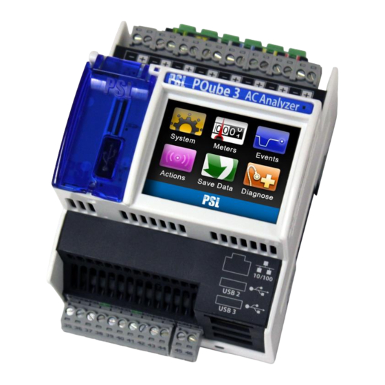
PQube 3 Instruction Manual 2.3 Overview of PQube 3 Ports, Connections, and Controls Coin-cell battery (keeps real time clock 10/100 Ethernet RJ-45 port. 48V PoE compatible. alive when instrument power is lost) USB-1 High-Speed USB 2.0 port for USB USB-2 Standard USB 1.0 port for use with ENV2 hard drives and adjacent microSD card environmental probes. -
Page 11: Choosing Modules
One USB drive included with each PQube 3 (contains manual, quickstart guide, setup file, Configurator program, Report Writer program) If you need additional functionality or inputs beyond the standard PQube 3 feature set, you can purchase optional modules for your PQube 3. -
Page 12: Power Your Pqube 3 From 100~240Vac
If you have 24~48Vdc or 24Vac, you can use your PQube 3’s internal power supply (just connect the voltage to the power supply screw terminal blocks). If you need to power your PQube 3 from 100~240Vac, you’ll need the plug-in PM1 or PM2 Power Manager module. -
Page 13: Measure The 1A Or 5A Secondary Wires Of External Current Transformers
It also includes an accelerometer to measure shock and vibration, a thermocouple input for wide temperature ranges, and a solar irradiation input. Connect up to 2 probes to your PQube 3 using a microUSB to USB cable. You can use a USB cable with a length of up to 3 meters. -
Page 14: Synchronize Your Pqube 3 To Gps Time
2.4.5 Synchronize your PQube 3 to GPS time Your PQube 3 can synchronize its time clock to GPS, which provides better than 1 microsecond accuracy. This is useful for Class A measurements, or if you need to make phasor measurements with a microPMU. -
Page 15: Installation Guide
CSA C22.1, CEC, Part I or with both as appropriate. In other countries, follow all local installation requirements and regulations. 3.1.2 Mount your PQube 3 properly and securely Your PQube 3, and its optional modules, are designed to be mounted on an industry-standard 35mm DIN rail as rack- or panel-mounted equipment. Example installation:... -
Page 16: Include Overcurrent Protection And A Disconnecting Device
ACCESSIBLE Your PQube 3 can also be installed without a cover if installed in a lockable IUL 508 control panel. The operator must be protected from the hazardous screw terminal blocks by a barrier. The screw terminal blocks must be made “not... - Page 17 PQube 3 Instruction Manual If you choose to install your PQube 3 in an enclosure, select a UL-listed enclosure that is appropriate for the purpose. If you plan to use an enclosure of this type, you should review its mechanical compatibility with any optional features of your PQube 3 that you plan to use: optional USB connections, optional temperature-humidity probes, etc.
-
Page 18: Connect Your Pqube 3 To The Power Supply
3.1.5.1 PQube 3 power supply terminals The instrument power terminals (45 and 46) on the front of your PQube 3 must be connected to 24VAC (±20%) or 24–48VDC (±20%), supplied by a certified isolating power supply. WARNING: Applying voltages outside of this range can cause permanent damage to your PQube 3. - Page 19 The PM1 or PM2 module accepts a range of 100~240VAC, 50/60/400Hz. It snaps into the right side of your PQube 3. This module is ideal for applications where 24-48VDC, 24VAC, and PoE are not available. Make sure your AC source can supply at least 20W.
-
Page 20: Connecting The Wires
PQube 3 Instruction Manual 3.1.6 Connecting the wires Observe the wire size specifications and limitations. All conductors must be stranded copper. All conductors and insulation systems and crimped devices must be appropriate for the application. PSL recommends crimped ferrules on stranded wire. Tighten the screws on the high voltage terminal block to 0,5 newton-meters (5 inch-pounds) of torque. - Page 21 PQube 3 Instruction Manual 3.1.6.2 Maximum voltages Connection Measurement Maximum Limitations and remarks Category current PQube 3 terminals 600 Vrms, CAT III L1, L2, L3, N Corresponds to 480V L-N / 830V L-L max for 3-phase, 4- wire Wye/Star systems.
-
Page 22: Connect Mains Ac Voltage Wires
PQube 3 Instruction Manual 3.1.7 Connect mains AC voltage wires The large high voltage terminal block on the back of your PQube 3 is removable. Refer to the wiring diagrams on page 29 and use the appropriate wiring scheme for your power configuration. -
Page 23: Protect Antenna Terminals From Lightning
3.1.9 Installing Your PM1 Power Supply Module PQube 3 The optional PM1 Power Supply Module connects to the right side of your PQube 3; just snap it in. It accepts any 50/60/400 Hz single-phase input between 100Vac and 240Vac nominal. Verify that you are connecting the line and neutral wires to the correct terminals on the module. -
Page 24: Installing Current Transformers (Cts)
PQube 3 Instruction Manual 3.1.11 Installing Current Transformers (CTs) Your PQube 3 records AC current by measuring the secondary circuit of a current transformer (CT). When installing current transformers, it is important to match the phases to the voltage inputs and current input (connect the L1 voltage input and the L1 current sensor to the same conductor). - Page 25 Your PQube 3 comes standard with 8 current input channels, which are typically used to measure L1, L2, L3, N, E, plus 3 additional single-phase channels. The current channels on your PQube 3 are rated for 0.333V nominal input, and they are designed to be used with CTs with 0.333V secondary.
- Page 26 The CTI module inputs are installed in series with your 1A or 5A secondary circuit. The terminal block on your CTI module is connected to the 0.333V current input channels on your PQube 3. Each CTI module includes 4 current channels, so you can use up to 2 CTI modules per PQube 3.
-
Page 27: Connecting The Env2 Environmental Probes
3.1.13 Installing Your MS1 Sync Module (GPS option) The optional MS1 Sync Module connects to the left side of your PQube 3; just snap it in. Connect the module before supplying power to your PQube 3. The MS1 Sync Module interfaces with the PSL GPS1 module using a special 8-pin cable at the MS1 module and an RJ45 connection at the GPS1 receiver. - Page 28 PQube 3 Instruction Manual 3.1.13.1 MS1 module to GPS1 receiver 8-pin cable pinouts: MS1 Pin-Out with pin 1 on left while GPS Receiver Pin-Out based on standard looking at module from the front RJ-45 Ethernet pin-out Function: Wire Color*: Function:...
-
Page 29: Wiring Diagrams
PQube 3 Instruction Manual 3.2 Wiring Diagrams 3.2.1 Single Phase L1-N 3.2.2 Single Phase L1-L2 Page 29 of 103 PowerMeterStore 1.877.766.5412 www. Shop for Power Metering products online at:... -
Page 30: Single Split Phase
PQube 3 Instruction Manual 3.2.3 Single Split Phase 3.2.4 Delta – 3 CTs Page 30 of 103 PowerMeterStore 1.877.766.5412 www. Shop for Power Metering products online at:... -
Page 31: Delta - 2 Cts (Pqube 3 Calculates Current On Remaining Channel)
PQube 3 Instruction Manual 3.2.5 Delta – 2 CTs (PQube 3 calculates current on remaining channel) 3.2.6 Wye/Star Page 31 of 103 PowerMeterStore 1.877.766.5412 www. Shop for Power Metering products online at:... -
Page 32: Measuring Neutral Current (Applies To Any Power Configuration With Neutral)
PQube 3 Instruction Manual 3.2.7 Measuring Neutral Current (applies to any power configuration with Neutral) 3.2.8 Measuring Earth Current (applies to any power configuration) Page 32 of 103 PowerMeterStore 1.877.766.5412 www. Shop for Power Metering products online at:... -
Page 33: Measuring Net Earth Current - Delta
PQube 3 Instruction Manual 3.2.9 Measuring Net Earth Current – Delta 3.2.10 Measuring Net Earth Current – Wye/Star Page 33 of 103 PowerMeterStore 1.877.766.5412 www. Shop for Power Metering products online at:... -
Page 34: Low Voltage Input/Output Terminals
PQube 3 Instruction Manual 3.3 Low Voltage Input/Output Terminals Phoenix Contact MC 1,5/ 2-ST-3,5 - 1840366 Phoenix Contact MC 1,5/10-ST-3,5 - 1840447 Page 34 of 103 PowerMeterStore 1.877.766.5412 www. Shop for Power Metering products online at:... -
Page 35: Your Setup File
FTP, and it will automatically reboot and load the new settings on startup. You can also copy your new Setup file onto a USB drive or microSD card and insert it directly into your PQube 3. After detecting the new Setup file, your PQube will ask you to reboot so it can load the new settings. -
Page 36: Initial Device Setup
PQube 3 Instruction Manual 4.2 Initial Device Setup Your PQube 3 will work right out of the box. Once your PQube 3 has been installed, connected to the monitoring circuit, and powered on, it will begin recording data immediately. The default settings will work for most applications, but if you have special requirements you may need to change a few settings. -
Page 37: Set Your Potential Transformer (Pt) Ratio
In setup file, set the PT ratio to 24000:240 or 100:1. You will also need to set your nominal voltage using the primary voltage of your PT. Even though your PQube 3 has 240V applied to its mains AC voltage terminals, you need to set the nominal voltage to 24000. -
Page 38: Set Your Current Transformer (Ct) Ratio
PQube 3 Instruction Manual 4.2.4 Set Your Current Transformer (CT) Ratio 4.2.4.1 If you are using CTs with 0.333V secondary To set the CT ratio, simply enter the primary current and secondary voltage into your CT ratio. For example, if you have a current transformer rated at 300 amps, with 0.333V secondary, then you would set your CT ratio to 300:0.333. -
Page 39: Verify Your Pqube 3 Has Been Configured Correctly
4.2.6.1 Negative Sequence Unbalance Excessively High If your PQube 3 reports an excessively high negative sequence unbalance ratio, this means your phase rotation is reversed. If you were connecting a 3-phase motor using this sequence, it would begin rotating in the opposite direction as intended. To change your phase rotation, swap any 2 phases. - Page 40 First, verify that you have at least 30VAC applied between the L1 and N terminals or the L1 and L2 terminals. Next, verify that you’ve connected the Earth conductor to your PQube 3. If you forget to install the Earth conductor to your PQube 3, your PQube 3 may have problems locking onto the power configuration.
-
Page 41: Pqube 3 Operation
PQube 3 Operation 5.1 User Controls 5.1.1 Navigating the Touchscreen Display Use the touchscreen on your PQube 3 to navigate the display. You can view live meters, recent events, system information, and perform actions like ejecting removable media and rebooting the unit. - Page 42 Your PQube 3 will automatically set the correct day of week. If you have enabled SNTP or NTP in your Setup.ini file, your PQube 3 will synchronize to UTC time, then it applies the offset from UTC as specified in your Setup file so that all measurements are time tagged with local time (in this example Pacific Time PST).
- Page 43 PQube 3 Instruction Manual Advanced: UPS battery status and GPS synchronization status are available here. Coming soon! You will be able to view status of your signal relay(s) and your PM2’s 24V auxiliary outputs. 5.1.1.2 Meters Voltage and Frequency: These are line-to-line, line-to-neutral, and neutral-to-earth true-RMS voltmeters.
- Page 44 PQube 3 Instruction Manual Power: These are the true power, apparent power, and reactive power readings, and they correctly handle harmonics (distorted voltages and distorted currents). If you have set a current transformer ratio and/or potential transformer ratio in your Setup.ini file, then these meters will reflect those ratios.
- Page 45 Use this screen to view every harmonic up to the 50 for both voltage and current. Select one harmonic at a time. The selected harmonic applies to all channels. (Harmonic values up to the 63 are recorded in your PQube 3’s CSV files.) Page 45 of 103 PowerMeterStore 1.877.766.5412 www.
- Page 46 PQube 3 Instruction Manual Interharmonics: Use this screen to view every interharmonic up to the 50 for both voltage and current. Select one harmonic at a time. The selected interharmonic applies to all channels. (Harmonic values up to the 63 are recorded in your PQube 3’s CSV files.)
- Page 47 PQube 3 Instruction Manual KYZ Pulse Output: Coming soon! Use for revenue-grade energy applications. 5.1.1.3 Recent Events Your PQube displays the 10 most recent events. For each event, you get date/time, event type, and magnitude/duration if applicable. Use the up/down arrows to navigate the list.
- Page 48 Eject: Use this button to safely remove any flash media (USB or microSD) that you have plugged into your PQube 3. Clear: Use this button to clear all events and trends from your PQube 3. 5.1.1.5 Save Files USB: Use this button to save your recorded data to the USB drive. For now you are able to copy all of the data to the drive, but in a future update you will be able to choose data only from today, this week, or this month as well.
-
Page 49: Rebooting Your Pqube 3
Rebooting Your PQube 3 5.1.2 5.1.2.1 To perform a software reboot You can do a software reboot your PQube 3 using two methods: Touchscreen – From main menu, go to Actions, then Reboot. Web server – Commands page 5.1.2.2 To perform a hardware reboot If you cannot perform a software reboot, press the reset button near the microSD card slot with a paperclip. -
Page 50: Ejecting Your Usb Thumb Drive Or Microsd Card
PQube 3 Instruction Manual 5.1.3 Ejecting your USB thumb drive or microSD card You can insert a USB thumb drive or microSD card into your PQube 3. Your PQube 3 will automatically detect it. To remove the USB drive or microSD card, go to the Actions screen and press the Eject button. -
Page 51: Accessing The Ftp Server On Your Pqube 3
PQube 3 Instruction Manual 5.2 Accessing the FTP Server on Your PQube 3 Your PQube 3 has a built-in plain FTP server which you can access using any standard FTP client. There are 5 different FTP accounts available. 1. ftp_user_1, ftp_user_2, ftp_user_3 Use these accounts to access events, trends, and logs. -
Page 52: Accessing The Http Web Server On Your Pqube 3
Have a valid IP address assigned to it (assigned by DHCP or fixed IP) To access your PQube 3 online, enter the IP address of the PQube 3 into your Internet Browser. Your browser will automatically direct you to the main Status page. -
Page 53: Status
PQube 3 Instruction Manual 5.3.1 Status PQube Location name & PQube ID as specified in your Setup file Note 1 and Note 2 from your Setup file PQube 3 serial number and model number PQube3 IP address Power configuration, nominal voltage, &... -
Page 54: Meters
PQube 3 Instruction Manual 5.3.2 Meters The page displays and refreshes regularly the various meters. The meters list depends on the power configurations, channels set to be recorded and environment probes connected. You can manually refresh the meters at any time by pressing the refresh button. -
Page 55: Events
PQube 3 Instruction Manual 5.3.3 Events The page displays the list of events organized around years, and months. Clicking the links provides access to more details down the data files and graphs for each of the events. You can refresh the events listing at any time by pressing the refresh button. -
Page 56: Trends
PQube 3 Instruction Manual 5.3.4 Trends You can refresh the trends listing at any time by pressing the refresh button. Links to daily/weekly/ monthly trend files Clicking on “File List” brings the list of daily trends for each Clicking on “File List”... -
Page 57: Commands
From the Commands page, you can trigger snapshots or daily trends, send test emails, or reset your PQube 3. You can also apply new setup files and firmware updates from here. You can restrict access to this page by specifying a username and password for the HTTP Administrator in your setup file. -
Page 58: Pqube 3 Email Setup
5.4 PQube 3 Email Setup You can configure your PQube 3 to send you an email whenever new data is available, or if there is any system activity. You can also execute commands on your PQube 3 by sending emails with the command name in the subject line. -
Page 59: Getting Event Notifications And Trend Data From Your Pqube 3 By Email
5.4.2 Getting event notifications and trend data from your PQube 3 by email To begin with, choose what type of data you would like to receive from your PQube 3. You can choose Event data, Trend data, Reset emails, or all email types. If applicable, your PQube 3 will include output files as attachments. -
Page 60: Sending Commands To Your Pqube 3 Over Email
To begin with, enable Incoming Emails [to your PQube 3] by checking the box labeled Incoming Emails at the Email Commands to PQube 3 tab. Your PQube 3 will log into its email account at regular intervals. You can set this interval (in seconds) at this section. - Page 61 FTP. Send Logs You can ask your PQube 3 to send you its log files via e-mail. The log files can help diagnose PQube setup problems, and they show the complete history of your PQube.
-
Page 62: Modbus Setup
5.5 Modbus Setup 5.5.1 Basics Your PQube 3 has a built-in Modbus-over-TCP server that you can use to read meters and determine when new event or trend recordings are available. You can set the following parameters in your PQube 3’s setup.ini file: Modbus Base Address: The global base address from which all registers are offset. -
Page 63: Led Definitions
PQube 3 Instruction Manual 5.6 LED Definitions 5.6.1 PQube 3 Purple = Seeking phase lock Yellow = Ethernet Activity Green = Ethernet Link (still waiting to record data) Green = Locked onto power configuration = Disk activity (recording has started) -
Page 64: Ms1
PQube 3 Instruction Manual 5.6.2 MS1 Green = PPS pulse (blinks at 1Hz) Blue = GPS power ON Orange = Cross Trigger (future extension) 5.6.3 PM1/PM2 Green = AC input power detected Blue = 24V auxiliary outputs are ON (PM2 only) -
Page 65: Ups1
Green blinking at 2Hz = Acceleration event in progress (ENV2 only) blinking = Powered, but not communicating with PQube 3 solid = Transmitting event data to PQube 3 Page 65 of 103 PowerMeterStore 1.877.766.5412 www. Shop for Power Metering products online at:... -
Page 66: Upgrading The Firmware On Your Pqube 3
5.7.1.1 To apply firmware updates locally Copy updates.tar onto a USB thumb drive or microSD card, then insert it into your PQube 3. The update process will begin automatically and the device will restart after several minutes. PSL provides the firmware updates as compressed tar files. Make sure the file name is updates.tar when you copy it to your flash drive. - Page 67 PQube 3 Instruction Manual 5.7.1.3 Applying a firmware update over email If you have Incoming Email enabled on your PQube 3, you can attach updates.tar to an email and your PQube will download and process the file automatically. 5.7.1.4 Apply a firmware update over FTP Log into your PQube 3’s FTP server with the username ftp_updater.
-
Page 68: Maintenance
Contact PSL to replace the batteries. Do not attempt to replace the batteries yourself. If you need to store your PQube 3 and modules on the shelf for 3 months or longer, all you need to do is charge your UPS1 module up to full before putting it away. Simply turn on your PQube 3 with the UPS1 module, and let it run for at least 20 hours to ensure a full charge. -
Page 69: Cleaning Instructions
5.8.5 Cleaning Instructions If necessary, wipe the accessible parts of your PQube 3 with a slightly damp cloth while it is powered off. Do not use abrasives or chemical cleaners and do not clean your PQube 3 while it is powered on. -
Page 70: Appendix 1: Setup File Guide
PQube 3 Instruction Manual Appendix 1: Setup File Guide 6.1.1 Device Setup Setup.ini Tags Comments Valid Values Example [PQube_Information] General Information about your PQube PQube_ID="PSL PQube in PSL Cal Lab" The unique identifier will appear on all output Any combination information. - Page 71 By default the autonomy is 3 minutes. Fan_Temperature_Threshold= Your PQube 3's internal fan turns on when the 40-60 CPU temperature exceeds this threshold. By default, the temperature threshold for the internal fan is 60.
- Page 72 PQube 3 Instruction Manual English-American Serbian English-British Slovakian English-India Slovenian Finish Spanish-LatinAmerica French-Canada Spanish-Mexico French-France Spanish-Spain German Swedish Greek Tagalog Hebrew Thai Hindi-Devenagari Turkish Indonesian- Ukrainian Bahasa Vietnamese Italian Japanese Korean [Nominal_Inputs] Nominal_Phase_To_Phase_Voltage=AUTO By default, your PQube will automatically detect...
- Page 73 ; ------ Valid Values: ON, OFF ; ------ Choose the number of samples/cycle for waveform recordings Recorded_Samples_Per_Cycle=256 ; ------ This does not change your PQube 3's sampling rate, only the level of detail in your waveform graphs. Your PQube 3 always samples at 512 samples/cycle.
- Page 74 PQube 3 Instruction Manual Modbus), GIFs, and CSV files. Record_Current_I1_I2_I3_Channel=OFF New tags in PQube 3. You can choose to show or AUTO hide any or all of the 8 current channels. Record_Current_I4_Channel=AUTO Record_Current_I5_Channel=AUTO Record_Current_I6_Channel=OFF Record_Current_I7_Channel=OFF Record_Current_I8_Channel=OFF Record_AN1_E_Channel=AUTO The AUTO setting records the Analog and Digital...
- Page 75 PQube 3 Instruction Manual KYZ_Relay_in_Wh_per_Pulse=0 Energy output KYZ, expressed in Watt-hour per 0 (to disable output) pulse. Any number Record_IEC_61000-4-30_10_Min_Interval=OFF Enable 10-minute and 2-hour interval trend recordings in a separate CSV file, per the requirements of IEC 61000-4-30 Class A.
- Page 76 PQube 3 Instruction Manual transformer. Current_Transformer_Ratio=1:1 When using PSL CTs with 0.333V secondary From Current_Transformer_Ratio= rating, the second number is the voltage. 50000:1 5:0.333 Neutral_Current_Transformer_Ratio=1:1 fractional values such Earth_Current_Transformer_Ratio=1:1 100.35:0.333 Current_I6_Transformer_Ratio=1:1 If the CT ratio is high enough, your PQube will automatically switch the units to kA.
- Page 77 PQube 3 Instruction Manual Apply voltage to AN1 and current to AN2. Apply voltage to AN3 and current to AN4. AN1_E_Channel_Ratio=1:1 You can use fractional values. From 10000:1 AN2_E_Channel_Ratio=1:1 AN3_E_Channel_Ratio=1:1 AN4_E_Channel_Ratio=1:1 AN1_E_Range="HIGH" Range for ANx_E input channels. HIGH AN2_E_Range="HIGH" HIGH range is (±100V Full scale) AN3_E_Range="HIGH"...
- Page 78 PQube 3 Instruction Manual Probe_A_Serial_Number= If these tags are left blank, Probe_A is the first Serial Number: detected probe, Probe_B is the second detected E300xxxx Probe_A_Channel_Name= probe. Valid names can Probe_B_Serial_Number= The environment Probe serial number format is be up to 7 "E"...
-
Page 79: Event Triggering
PQube 3 Instruction Manual 6.1.2 Event Triggering Setup.ini Tags Comments Valid Values Example [Phase_To_Neutral_Events] Phase_To_Neutral_Events=AUTO Use the AUTO setting to let your PQube decide to AUTO record Phase-Neutral events. If your Power Configuration includes a Neutral conductor, your PQube will record Phase-Neutral events. - Page 80 PQube 3 Instruction Manual [Phase_To_Neutral_RVC_Events] Phase_To_Neutral_RVC_Events=AUTO AUTO Phase_To_Neutral_RVC_Threshold_In_Percent=2.5 Phase_To_Neutral_RVC_Hysteresis_In_Percent=1.5 [Phase_To_Phase_RVC_Events] Phase_To_Phase_RVC_Events=AUTO AUTO Phase_To_Phase_RVC_Threshold_In_Percent=6 Phase_To_Phase_RVC_Hysteresis_In_Percent=2 [Snapshot_Events] Waveform_Snapshot_Interval_In_Hours=24 Trigger a waveform/RMS recording at scheduled time intervals. Enable_Snapshot_Harmonics=ON Toggle Snapshot harmonic recordings Waveform_Snapshot_At_Startup=OFF Set this tag to ON to take a Snapshot of your electric power every time your PQube is powered on or reset.
- Page 81 PQube 3 Instruction Manual [AN1_E_Events] AN1_E_Events=OFF Set this tag to ON or OFF to toggle event triggering on your AN1-E channel. Set the value to USER_COUNTER to increment a USER_COUNTER* counter every time an event occurs on this channel (no events, waveforms, or RMS envelopes will be generated).
- Page 82 PQube 3 Instruction Manual * USER_COUNTER not yet supported AN1_AN2_Dip_Threshold_In_Volts=2.00 Set event detection thresholds for AN1-AN2 Use the values after voltage. being transformed by the AN1_AN2_Swell_Threshold_In_Volts=60.00 Analog ratios, not the actual voltage coming AN1_AN2_Event_Hysteresis_In_Volts=0.5 into the Analog terminals. [AN3_E_Events] AN3_E_Events=OFF Set this tag to ON or OFF to toggle event triggering on your AN3-E channel.
- Page 83 PQube 3 Instruction Manual on your AN3-AN4 channel. Set the value to USER_COUNTER to increment a USER_COUNTER* counter every time an event occurs on this channel (no events, waveforms, or RMS envelopes will be generated). * USER_COUNTER not yet supported AN3_AN4_Dip_Threshold_In_Volts=2.00...
- Page 84 PQube 3 Instruction Manual Example: CT ratio = 100A:0.333V Full-scale of current input=0.333V 100:0.333 * 0.333 = 100A AUTO for hysteresis defaults to 4% of threshold. Phase_Current_Inrush_Threshold_In_Amps= Set the inrush threshold here. Your PQube will AUTO AUTO record an event when the increase of current...
- Page 85 PQube 3 Instruction Manual CT ratio = 100A:0.333V Full-scale of current input=0.333V 100:0.333 * 0.333 = 100A AUTO for hysteresis defaults to 4% of threshold. Neutral_Current_Inrush_Threshold_In_Amps Set the inrush threshold here. Your PQube will AUTO =AUTO record an event when the increase of current...
- Page 86 PQube 3 Instruction Manual 100:0.333 * 0.333 = 100A AUTO for hysteresis defaults to 4% of threshold. Earth_Current_Inrush_Threshold_In_Amps= Set the inrush threshold here. Your PQube will AUTO AUTO record an event when the increase of current Any value greater exceeds the Inrush_Threshold_In_Amps value,...
- Page 87 PQube 3 Instruction Manual Major_Dip_Threshold_Level_4_Duration_in_Seconds=0 Major_Dip_Threshold_Level_2_Duration_in_Seconds=0.5 Example of invalid Usage: Major_Dip_Threshold_Level_1_in_Percent=70 Major_Dip_Threshold_Level_1_Duration_in_Seconds=2 Major_Dip_Threshold_Level_2_in_Percent=80 Major_Dip_Threshold_Level_2_Duration_in_Seconds=1 [Waveshape_Change_Events] Waveshape_Change_Events=ON Trigger a Waveshape Change when the voltage waveform changes abruptly. This is useful for detecting power factor correction capacitor switching. Voltage_Threshold_In_Percent_Of_Nominal=20.00 Uses the “Floating Window” algorithm. Each Nth...
- Page 88 PQube 3 Instruction Manual Probe_A_Undertemperature_Events=OFF temperature and humidity here. Probe_A_Undertemperature_Threshold_in_Deg_C=0 Probe_A_Overtemperature_Threshold_in_Deg_C=50 temperature Probe_A_Temperature_Event_Hysteresis_in_Deg_C=2 events, any number in degrees C. Probe_A_High_Humidity_Events=OFF For humidity Probe_A_Low_Humidity_Events=OFF events, any number in %RH. Probe_A_Low_Humidity_Threshold_in_Percent_RH=5 Probe_A_High_Humidity_Threshold_in_Percent_RH=9 Probe_A_Humidity_Event_Hysteresis_in_Percent_RH= Probe_B_Overtemperature_Events=OFF Probe_B_Undertemperature_Events=OFF Probe_B_Undertemperature_Threshold_in_Deg_C=0 Probe_B_Overtemperature_Threshold_in_Deg_C=50 Probe_B_Temperature_Event_Hysteresis_in_Deg_C=2 Probe_B_High_Humidity_Events=OFF Probe_B_Low_Humidity_Events=OFF Probe_B_Low_Humidity_Threshold_in_Percent_RH=5 Probe_B_High_Humidity_Threshold_in_Percent_RH=9...
-
Page 89: Network Configuration
IEC 61000-4-30 Class A Section 5.10. Mains_Signaling_Threshold_In_Volts=60 Define the threshold and recording period here. Mains_Signaling_Recording_Period_In_Seconds=60 Mains_Signaling_Channel=L1 Set which channel your PQube 3 monitors the Mains Signaling frequency on. Mains_Signaling_Harmonic_In_Hz= Specify the Mains Signaling frequency of interest. 6.1.3 Network Configuration Setup.ini Tags... - Page 90 IP_DNS1= IP_DNS2= [Email_Server_Settings] Set up the email account for your PQube 3 here. IMPORTANT: Your PQube needs its own e-mail account. Do not assign your personal email account to your PQube – PSL is not liable for any loss of data. All PQubes come with a free, temporary PQube.com e-mail account...
- Page 91 Email_Commands=OFF Toggle email commands (incoming emails to your PQube 3) Check_Every_N_Seconds=300 How often your PQube 3 checks its inbox for new email commands. IMPORTANT: For PQube 3, this interval is in seconds, not minutes (like the original PQube). Subject_Must_Begin_With=PQube3...
- Page 92 PQube 3 Instruction Manual Enable_Event_Summary_Email=OFF Summary emails are short, plain-text event notifications. These are typically sent to a manager who does not need the specific details of an event. Send_Reset_Emails=ON Choose which types of emails you want from your PQube. Useful for reducing your data usage by Send_Events_Emails=ON receiving only the types of emails that you need.
- Page 93 PQube 3 Instruction Manual Email_To_1= and attachments. Email_To_2= Email_To_3= Email_To_4= Email_To_5= ; ------ CC Distribution list of emails Email_CC_1= Email_CC_2= Email_CC_3= Email_CC_4= Email_CC_5= ; ------ BCC Distribution list of emails Email_BCC_1= Email_BCC_2= Email_BCC_3= Email_BCC_4= Email_BCC_5= Email_Errors_To= The recipient in the Errors_To field will receive a...
-
Page 94: Protocols And Synchronization
PQube 3 Instruction Manual 6.1.4 Protocols and Synchronization [Modbus] Modbus_Slave_Device_Address=1 Set according to the Modbus SCADA/master application Modbus_TCP_port=502 Set according to the Modbus SCADA/master application Modbus_Register_Start_Address=7000 Byte_Order=BIG_ENDIAN Big Endian byte order stores the most significant BIG_ENDIAN number in the first byte. - Page 95 Enable_SNTP=OFF Synchronize your PQube’s time clock using SNTP SNTP_Server=pool.ntp.org Set the SNTP server address. SNTP_Update_Interval_In_Hours=24 Define how often your PQube 3 synchronizes with 1 to 168 the SNTP server. [NTP_Settings] Your PQube can synchronize its clock to UTC using Network Time Protocol (NTP).
-
Page 96: System And Services
PQube’s Web Server (tag default OFF) , you will be HTTP_Admin_User_Name=admin prompted with user and password to access the web pages HTTP_Admin_Password=admin [FTP Settings] Manage the built-in FTP server in your PQube 3. FTP_Password_1= You can manage up to 5 FTP users: Those users are: FTP_Password_2= ftp_user_1 ftp_user_2... -
Page 97: Trend Setup
PQube 3 Instruction Manual 6.1.6 Trend Setup Setup.ini Tags Comments Valid Values Example [Trend_Settings] Enable_Daily_Trends=ON Daily Trends and Statistics are recorded every midnight. Enable_Weekly_Trends=ON Weekly Trends and Statistics are recorded every Enable_Monthly_Trends=ON midnight between Sunday and Monday using ISO 8601 methods. - Page 98 PQube 3 Instruction Manual Max_Current_of_Interest_in_Amps=AUTO* does not provide a suitable graph. [amps] The AUTO setting is determined by your full-scale current. *AUTO not yet available for this tag Min_Neutral_Current_of_Interest_in_Amps=AUTO* If your PQube is calculating the Earth Current, AUTO AUTO sets the Max_Earth_Current_of_Interest_in_Amps to...
- Page 99 PQube 3 Instruction Manual Max_AN1_AN2_of_Interest_in_RMS_volts=AUTO* *AUTO not yet available for this tag Any number [volts] Min_AN3_E_of_Interest_in_RMS_volts=AUTO* The AUTO values are determined by the Dip and Swell AUTO thresholds on Analog Channel 3. Max_AN3_E_of_Interest_in_RMS_volts=AUTO* Any number [volts] *AUTO not yet available for this tag...
-
Page 100: Appendix 2: Major Dip Curves
PQube 3 Instruction Manual Appendix 2: Major Dip Curves Your PQube supports the following world-wide standards: STANDARD (IEC 61000-4-34), SEMI F47, Samsung Power Vaccine, ITIC, CBEMA, MIL-STD 704E, and MIL-STD 1399. These standards define ride-through curves based on the depth and duration of voltage dips. When the voltage dips below the ride-through curve, your PQube will trigger a Major Dip event. -
Page 101: Semi F47
PQube 3 Instruction Manual 7.1.2 SEMI F47 NOTE: Use this curve to guarantee that a Major Dip is detected for events that lie directly on the SEMI F47 boundary. 7.1.3 Samsung Power Vaccine Page 101 of 103 PowerMeterStore 1.877.766.5412 www. -
Page 102: Itic
PQube 3 Instruction Manual 7.1.4 ITIC 7.1.5 CBEMA Page 102 of 103 PowerMeterStore 1.877.766.5412 www. Shop for Power Metering products online at:... -
Page 103: Mil-Std 704E
PQube 3 Instruction Manual 7.1.6 MIL-STD 704E 7.1.7 MIL-STD 1399 Page 103 of 103 PowerMeterStore 1.877.766.5412 www. Shop for Power Metering products online at:...
Need help?
Do you have a question about the PQube 3 and is the answer not in the manual?
Questions and answers