
Summary of Contents for Warner CBC-300 Series
- Page 1 CBC-300 & CBC-300-1 Series Dual Channel Adjust Clutch/Brake Controls Installation & Operating Instructions P-2105-WE 819-0549 An Altra Industrial Motion Company...
-
Page 2: Table Of Contents
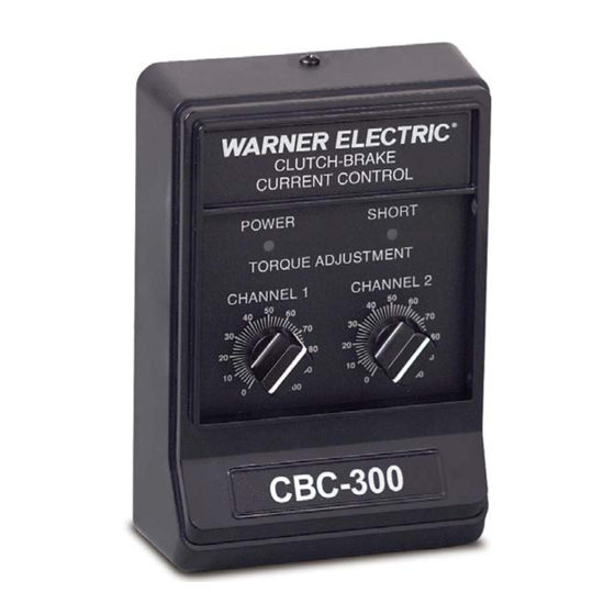
An internal 1 .5A FA fuse is provided for line to ground current, solid state electronic power supplies designed shorts . to operate any of the Warner Electric 90 Volt clutches and brakes, including fail safe designs . They can operate Two LED indicators are provided on the front panel of a single clutch or brake, two clutches, two brakes, the control for “POWER”... -
Page 3: Specifications
. Part Numbers: Enclosed Versions Internal Adjustments: Current Range Selection via DIP switches, SW1 for Channel 1 and SW2 for CBC-300 6021-448-009 Channel 2 . CBC-300-1 6021-448-002 Warner Electric • 800-825-9050 P-2105-WE 819-0549 5/17 3... -
Page 4: Mounting
. Refer to: External (165.1) Max. Potentiometer wiring for CBC-300-1, page 5 CBC-300 CBC-300-1 q 2 . If the CBC-300 control is used, refer to: Final Wiring, page 6 CBC-300 CBC-300-1 (Figure 1) 4 Warner Electric • 800-825-9050 P-2105-WE 819-0549 5/17... - Page 5 Note: Be careful not to pinch or crimp the pot wiring to prevent shorting to the housing or components . 10K, 2W POT 10% TOL, LINEAR OR 6011-101-002 ACCESSORY KIT (1) (Figure 7) Warner Electric • 800-825-9050 P-2105-WE 819-0549 5/17 5...
-
Page 6: Electrical Connections
Note: If Solid-state NPN switching External switching by is used, emitter is connected to customer, see terminal 6 or 9 and collector is specification. connected to terminal 5 or 8. (Figure 3) 6 Warner Electric • 800-825-9050 P-2105-WE 819-0549 5/17... - Page 7 Note: If Solid-state NPN switching 120 VAC is used, emitter is connected to terminal 6 or 9 and collector is External switching by connected to terminal 5 or 8. customer, see specification. (Figure 4) Warner Electric • 800-825-9050 P-2105-WE 819-0549 5/17 7...
-
Page 8: Internal Adjustments
The internal DIP Switch on the control circuit board adjusts the control for the proper current range to the clutch and/or brake coil being used . The Chart below indicates the proper setting based on coil resistance and Warner Electric product . -
Page 9: Troubleshooting Checklist
Torque adjust potentiometer set too low • Check setting of torque adjust potentiometer and set to maximum if required . Magnets are incorrectly sized • Verify sizing is correct by repeating selection process . Warner Electric • 800-825-9050 P-2105-WE 819-0549 5/17 9... -
Page 10: Warranty
Warner Electric LLC be liable for consequential, indirect, or incidental damages of any kind incurred by reason of the manufacture, sale or use of any defective product . Warner Electric LLC neither assumes nor authorizes any other person to give any other warranty or to assume any other obligation or liability on its behalf .
Need help?
Do you have a question about the CBC-300 Series and is the answer not in the manual?
Questions and answers