
Summary of Contents for SMC Corporation PF2A301-A-Ni
- Page 1 No.PF##-OMG0008-B PRODUCT NAME Flow Monitor MODEL / Series / Product Number PF2A3## PF2W3## PF2D3##...
-
Page 2: Table Of Contents
Table of Contents Safety Instructions Model Indication and How to Order Summary of Product parts Definition and terminology Mounting and Installation Installation Wiring Outline of setting List of outputs Initialize mode Default settings Setting procedure of Initialize mode Function selection mode Default settings F_1 Input procedure of the Set value of instantaneous output F_2 Input procedure of the Set value of instantaneous output (Auto-preset) -
Page 3: Safety Instructions
Safety Instructions These safety instructions are intended to prevent hazardous situations and/or equipment damage. These instructions indicate the level of potential hazard with the labels of "Caution", "Warning" or "Danger". They are all important notes for safety and must be followed in addition to International ∗1) standards (ISO/IEC) and other safety regulations. - Page 4 Caution The product is provided for use in manufacturing industries. The product herein described is basically provided for peaceful use in manufacturing industries. If considering using the product in other industries, consult SMC beforehand and exchange specifications or a contract if necessary. If anything is unclear, contact your nearest sales branch.
- Page 5 Operator ♦This operation manual is intended for those who have knowledge of machinery using pneumatic equipment, and have sufficient knowledge of assembly, operation and maintenance of such equipment. Only those persons are allowed to perform assembly, operation and maintenance. ♦Read and understand this operation manual carefully before assembling, operating or providing maintenance to the product.
- Page 6 ■NOTE ○Follow the instructions given below when designing, selecting and handling the product. ●The instructions on design and selection (installation, wiring, environment, adjustment, operation, described below must also be followed. maintenance, etc.) ∗Product specifications •Use the specified voltage. Otherwise failure or malfunction can result. Insufficient supply voltage may not drive a load due to a voltage drop inside the product.
- Page 7 ●Product handling ∗Installation •Do not apply excessive stress to the product when it is panel mounted. Otherwise damage to the product and disconnection from the panel mount can result. •Ensure that the FG terminal is connected to ground when using a commercially available switch-mode power supply.
- Page 8 ∗Environment •Do not use the product in area that is exposed to corrosive gases, chemicals, sea water, water or steam. Otherwise failure or malfunction can result. •Do not use in a place where the product could be splashed by oil or chemicals. If the product is to be used in an environment containing oils or chemicals such as coolant or cleaning solvent, even for a short time, it may be adversely affected (damage, malfunction, or hardening of the lead wires).
- Page 9 ∗Adjustment and Operation •Connect load before turning on the power. Otherwise it can cause excess current causing instantaneous damage to the product. •Do not short-circuit the load. Although an error is displayed when the product load is short circuited, excess current may cause the damage to the product.
-
Page 10: Model Indication And How To Order
Model indication and How to Order No.PF##-OMG0008-B... - Page 11 Accessories / Part number If an accessory is required separately, order using the following part numbers. Part number Description Remarks Weight ZS-22-E Panel mount adapter 15 g -10- No.PF##-OMG0008-B...
-
Page 12: Summary Of Product Parts
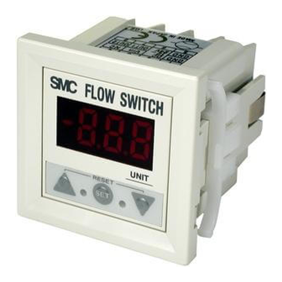
Summary of Product parts Front Item Description Indicates the reference condition selected. LED is ON (Red) when normal condition is Indicator LED selected. (Only the PF2A3 LED display Displays the flow value, setting mode, and error indication. Indicates the output status of OUT1. LED is ON (Green) when OUT1 is ON. Indicator LED (OUT1) The LED flashes when an over current error occurs. -
Page 13: Definition And Terminology
■Definition and terminology Terms Meaning The total amount of fluid that has passed through the device. If an instantaneous flow of Accumulated flow 10 L/min continues for 5 minutes, the accumulated flow will be 10 x 5 = 50 L. Accumulated pulse A type of output where a pulse is generated every time a predefined accumulated flow output... - Page 14 Terms Meaning The range of ON/OFF threshold values that can be set for those products with a switch Setting flow range output. Standard condition Flow display which is converted in atmospheric pressure at 20 C°, 65%R.H. Output type that has only 2 conditions, ON or OFF. In the ON condition, an indicator Switch output LED (output) will show, and any connected load will be powered.
-
Page 15: Mounting And Installation
Mounting and Installation ■Installation •Never mount the product in a location that will be used as a foothold. ●Installing Removing the panel mount adapter •Remove the panel mount adapter from the product if it has been delivered assembled. •Remove the mounting bracket using a flat blade screwdriver. •Lever the hook to the outside to remove the adapter (See below). - Page 16 Mounting with the panel mount adapter •Install the product as shown below. •Insert panel mount adapter B into section A of panel mount adapter A. Push panel mount adapter B from behind until the display is fixed onto the panel. The pin of panel mount adapter B engages the notched part of panel adapter section A to fix the display.
-
Page 17: Wiring
■Wiring •Connections should only be made with the power supply turned off. •Use separate routes for the product wiring and any power or high voltage wiring. Otherwise, malfunction may result due to noise. •Ensure that the FG terminal is connected to ground when using a commercially available switch-mode power supply. - Page 18 ●Internal circuit and wiring example Use sensor PF2 5 series for accurate measurement. NPN (2 outputs) type PF2 3 0-A- Max. 30 V, 80 mA Internal voltage drop: 1 V or less PNP (2 outputs) type PF2 3 1-A- Max. 80 mA Internal voltage drop: 1.5 V or less -17- No.PF##-OMG0008-B...
-
Page 19: Outline Of Setting
Outline of setting Power is supplied The output will not operate for 3 seconds after supplying power. The identification code of the product is displayed. Measurement mode The mode in which the flow is detected and displayed, and the switch function is operating. This is the basic operating mode;... -
Page 20: List Of Outputs
■List of outputs Find the diagram of the output required in the table below. Perform settings following the Set value column on the right. Characters in ( ) are for OUT2. Switch Switch output diagram Output mode Set value operation Set point 2 Set point 1 ∗... -
Page 21: Initialize Mode
Initialize mode ●Default settings The default settings are as follows. If this condition is acceptable, then keep these settings. Refer to the relevant page for changing the settings. •PF2A3 series Item Default settings Page PF2A30 series [10L] 1 to 10 L/min type (PF2A510) Selection of the connected sensor Page 21 PF2A31 series... -
Page 22: Setting Procedure Of Initialize Mode
■Setting procedure of Initialize mode <Operation> Press the button for 2 seconds or longer during measurement mode. Selection of the connected sensor The sensor to be connected is selectable before using the product. If the select connected sensor is changed, the Set value and the accumulated value are return to default setting. - Page 23 Selection of display mode Select the display of instantaneous flow or accumulated flow. Press the button to select. •[d_1]: display instantaneous flow •[d_2]: display accumulated flow The product with unit selection function Press the button. SI unit only Unit selection function The display unit can only be selected for products with unit selection unction.
- Page 24 Selection of output mode (OUT1) Select the switch output mode required referring to the list of outputs (page 19). Press the button to select. •[o10]: Instantaneous output mode •[o11]: Accumulated output mode •[o12]: Accumulated pulse output mode Press the button. Selection of output mode (OUT2) Select the switch output mode required referring to the list of outputs (page 19).
- Page 25 Selection of reference condition Operate only the PF2A3 series. Select standard condition or normal condition for the display unit. Press the button to select. •[ Anr]: Standard condition. Flow display which is converted in atmospheric pressure at 20 °C, 65%R.H. •[ nor]: Normal condition.
- Page 26 Flow specification when [U_2] is selected by the unit selection function •PF2A3 series Model PF2A30 PF2A31 Applicable sensor PF2A510 PF2A550 PF2A511 PF2A521 PF2A551 3.5 to 35.5 18 to 176 3.5 to 35.5 7 to 71 18 to 176 Rated flow range CFM x 10 CFM x 10 CFM x 10...
-
Page 27: Function Selection Mode
Function selection mode Function selection mode In measurement mode, press the button, to display [F_ ]. This [F_ ] indicates the mode for changing each functional setting. ∗: When OUT1 or OUT2 is assigned to be instantaneous output mode during initialize mode, [F_1] and [F_2] are displayed. When OUT1 or OUT2 is assigned to be accumulated output mode, [F_3] is displayed. -
Page 28: F_1 Input Procedure Of The Set Value Of Instantaneous Output
■[F_1] Input procedure of the Set value of instantaneous output The Set point of the switch output can be set manually. <Operation> Press the button in function selection mode to display [F_1]. (When OUT1 or OUT2 is assigned to be accumulated output mode, [F_1] is displayed.) Press the button. -
Page 29: F_2 Input Procedure Of The Set Value Of Instantaneous Output (Auto-Preset)
■[F_2] Input procedure of the Set value of instantaneous output (Auto-preset) The Set point of the switch output can be automatically set referring to actual flow. <Operation> Press the button in function selection mode to display [F_2]. (When OUT1 or OUT2 is assigned to be accumulate output mode, [F_2] is displayed.) Press the button. -
Page 30: F_3 Input Procedure Of The Set Value Of Accumulated Output
■[F_3] Input procedure of the Set value of accumulated output The Set point of the switch output can be manually set. Accumulated flow rate is displayed by the lower 3 digits and upper 3 digits separately. Setting is performed separately. <Operation>... - Page 31 [F_3] Input procedure of the Set value of accumulated output is completed. Return to measurement mode. Starting of accumulation Check that the display of accumulated flow rate is selected as the display mode. Press the buttons simultaneously in measurement mode. [-] flashes and accumulation starts.
-
Page 32: Key-Lock Function
Key-lock function This function is used to prevent errors occurring due to unintentional changes of the Set values. <How to lock> 1. Press the button for 3 seconds or longer in measurement mode. The display will change from [F_ ] to [ L] ([ d]) to [unL]. -
Page 33: Maintenance
Maintenance How to reset the product after a power cut or forcible de-energizing The setting of the product will be retained as it was before a power cut or de-energizing. The output condition is also basically recovered to that before a power cut or de-energizing, but may change depending on the operating environment. -
Page 34: Troubleshooting
Troubleshooting Troubleshooting If an operation failure occurs with the product, use the table below to find out the cause of the problem. If none of the countermeasures seem to be applicable, or a replacement product operates normally when installed, the product may be faulty. A product can be damaged by the operating environment (system configuration etc). - Page 35 Fault Probable cause Recommended action Wiring failure. Correct the wiring. There is no output. Connector loose. Check the connector. Foreign matter inside. Refer to the operation manual of the sensor. Install the sensor with the mounting direction Piping is connected in the wrong corresponding to the flow direction (arrow indicated direction.
-
Page 36: Error Indication
■Error indication Error Name Error Display Error Type Troubleshooting Method Excessive Flow has exceeded the upper limit of the Reduce the flow. instantaneous flow display flow range. OUT1 The switch output load current is more Turn the power off and remove over current error than 80 mA (OUT1). -
Page 37: Specifications
Specifications ■Specifications •PF2A3 Model PF2A3 Applicable sensor PF2A510 PF2A550 PF2A511 PF2A521 PF2A551 1 to 10 5 to 50 10 to 100 20 to 200 50 to 500 Rated flow range L/min L/min L/min L/min L/min Setting/display flow 0.5 to 10.5 2.5 to 52.5 5 to 105 10 to 210... - Page 38 •PF2W3 Model PF2W3 Applicable sensor PF2W504(T) PF2W520(T) PF2W540(T) PF2W511(T) 0.5 to 4.0 2 to 16 5 to 40 10 to 100 Rated flow range L/min L/min L/min L/min Setting/display flow 0.35 to 4.50 1.7 to 17.0 3.5 to 45.0 7 to 110 ∗...
- Page 39 •PF2D3 Model PF2D3 Applicable sensor PF2D504 PF2D520 PF2D540 0.4 to 4.0 1.8 to 20.0 4 to 40 Rated flow range L/min L/min L/min Setting/display flow 0.25 to 4.50 1.3 to 21.0 2.5 to 45.0 ∗ 1 range L/min L/min L/min 0.05 Min.
- Page 40 •Common Specifications Model PF2 3 Display part Displayed digit: 3 digits 7 segments, Colour: Red OUT1: When ON, Green LED ON Indicator LED OUT2: When ON, Red LED is ON Enclosure IP40 Operation: 0 to 50 °C, Storage: -25 to 85 °C (no freezing or condensation) Operating temperature range Operation, Storage: 35 to 85%R.H.
-
Page 41: Dimensions
■Dimensions (in mm) PF2 3 + Panel mount adapter (ZS-22-E) Panel cut-out dimensions ∗: Suitable for panel thickness of 1 to 3.2 mm. -40- No.PF##-OMG0008-B... - Page 42 B: Content is changed due to the change of the format. Note: Specifications are subject to change without prior notice and any obligation on the part of the manufacturer. © 2011 SMC Corporation All Rights Reserved No.PF##-OMG0008-B...
Need help?
Do you have a question about the PF2A301-A-Ni and is the answer not in the manual?
Questions and answers