
Related Manuals for STM SatLink 1000


Summary of Contents for STM SatLink 1000
- Page 1 STM SatLink VSAT User Guide Copyright © 2006-2007 – STM Norway AS Publication no. 101557, Rev. U, August 9 , 2007 Page 1...
- Page 2 AS makes no warranty of any kind with regard to this material, including, but not limited to, the implied warranties or merchantability and fitness for particular purposes. Moreover, STM Norway AS shall not be held liable for errors that may occur herein or for incidental or consequential damage in connection with the furnishing, performance, or use of this material.
-
Page 3: Table Of Contents
Power on and logon.....................23 Initial configuration of parameters ................24 Line-up.........................34 Test of DVB-RCS connection ..................38 Prepare the STM SatLink VSAT for normal operation..........39 LAN DHCP SERVER AND DNS CONFIGURATION ..........40 Configuration of DNS....................40 Configuration of the DHCP server ................40 Changing the SatLink VSAT LAN Interface IP address..........41 QUALITY OF SERVICE ....................42... - Page 4 APPENDIX L. STANDARDISATION OF TIMING COMPENSATION........112 APPENDIX M. RECEIVER AND TRANSMITTER AUTO START .........113 APPENDIX N. ACCESSING THE FORWARD LINK SIGNALLING ........114 Copyright © 2006-2007 – STM Norway AS Publication no. 101557, Rev. U, August 9 , 2007 Page 4...
-
Page 5: Introduction
1. Introduction The STM SatLink 1000, 1900, 1901 and 1910 are the indoor units (IDUs) of the STM SatLink VSAT family of DVB-RCS VSATs. They perform several functions: they are satellite modems (at Layer 1); they handle data link layer processing (at Layer 2) for both satellite and LAN communications; and they act as IP routers and DHCP servers (at Layer 3). -
Page 6: About This User Guide
STM SatLink 4035, P/N 106546 Initial Configuration The STM SatLink VSAT IDU must be configured before it can communicate via the satellite to and from the network Hub. The parameters to be configured are explained in section 6.2. The configuration of the VSAT IDU can be carried out using the configuration tools: •... -
Page 7: Unpacking
2. Unpacking Check that the following items are in the box received, then unpack. • SatLink 1000, 1900, 1901, or 1910 • Stand for vertical placement (SatLink 1000 only) • AC adapter (SatLink 1000 only) • Mains cord • Brackets for 19” rack mounting (SatLink 1900/1901/1910 only) Copyright ©... -
Page 8: Installation
Determine if the victim needs artificial respiration or external cardiac compressions; then take appropriate action. 3.1.2 Site requirements The STM SatLink VSAT IDU shall be connected to the mains 110/230 VAC, 50-60Hz. Copyright © 2006-2007 – STM Norway AS Publication no. 101557, Rev. U, August 9... -
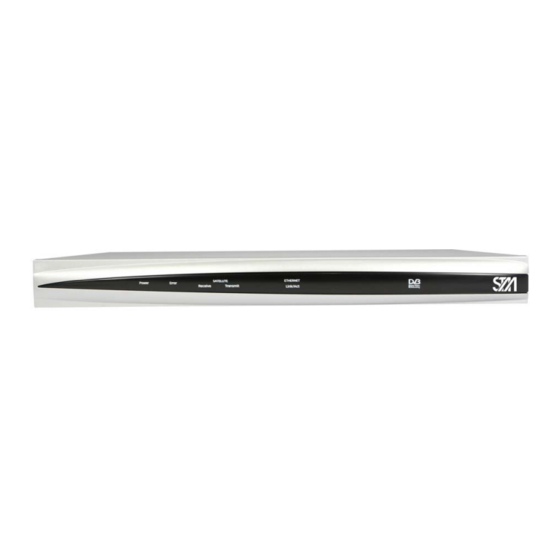
Page 9: Satlink Vsat Idu Front And Back Panels
SatLink VSAT IDU front and back panels 3.2.1 SatLink 1000 front and back panel Figure 3: SatLink 1000 Front panel Colour, indicates Blue, lights steadily when power switch is on and unit is powered. Flashes when loading Power software. Red, lights steadily when an error event occurs and during reboot. - Page 10 Coaxial 75 Ω F-type jack for the cable to the BUC. Tx coaxial jack Table 4: Description of SatLink 1910 back panel Copyright © 2006-2007 – STM Norway AS Publication no. 101557, Rev. U, August 9 , 2007 Page 10...
- Page 11 Coaxial 75 Ω F-type jack for the cable to the BUC. Tx coaxial jack Table 6: SatLink 1900 and 1901 back panel connectors and switches Copyright © 2006-2007 – STM Norway AS Publication no. 101557, Rev. U, August 9 , 2007...
-
Page 12: Idu Installation
The STM SatLink 1900/1901/1910 can be mounted in any EIA-standard 19-inch telecommunications rack or cabinet. The STM SatLink 1000 needs to be placed on a shelf if it is to be placed in a rack. Use a Torx screwdriver and attach the mounting brackets to the router with the screws supplied. Hold the unit securely, brackets attached, and move it vertically until rack holes line up with the bracket notches, then insert and tighten the four screws holding the brackets to the rack. -
Page 13: Odu Installation
Interface connections 3.5.1 Rx/Tx cables between IDU and ODU The coaxial cables from the ODU are connected to the type F coaxial jacks on the back panel of the STM SatLink VSAT IDU. •... -
Page 14: Mains Connection
Toggle to NODE when connecting to an Ethernet switch or an Ethernet hub and toggle to HUB when connecting to a single PC. For the STM SatLink 1000 and 1910 there is no push button on the back panel as Ethernet HUB or NODE mode will be auto-detected and the correct mode chosen automatically. -
Page 15: Connecting A Pc To The Satlink Vsat
PC client to obtain the IP address automatically from the VSAT IDU (section 4.1.1) or configure the PC with a static IP address (section 4.1.2). Figure 10: Windows XP menu for configuring the client TCP/IP configuration. Copyright © 2006-2007 – STM Norway AS Publication no. 101557, Rev. U, August 9 , 2007... - Page 16 DHCP server such as IP address, subnet mask, default Gateway, DNS servers and lease time. Figure 12: ipconfig /all print out from an MS-DOS window Copyright © 2006-2007 – STM Norway AS Publication no. 101557, Rev. U, August 9 , 2007...
- Page 17 A host may have the following configuration; IP address 192.168.0.2, Subnet mask 255.255.255.0 and default gateway 192.168.0.1, where the IP address of the default gateway should be the IP address of the VSAT LAN interface. Copyright © 2006-2007 – STM Norway AS Publication no. 101557, Rev. U, August 9 , 2007...
-
Page 18: Using The Command Line Interface Of The Satlink Vsat
: IP configuration : Event log misc : Miscellaneous commands : ODU configuration : Software upgrade & licenses user : User configuration Copyright © 2006-2007 – STM Norway AS Publication no. 101557, Rev. U, August 9 , 2007 Page 18... -
Page 19: Logging Of Events
By default, Major and Critical events are logged to file. Copyright © 2006-2007 – STM Norway AS Publication no. 101557, Rev. U, August 9... -
Page 20: Cli Command Summary
<deg> <min> <mindec> <dir> dvb pos long <deg> <min> <mindec> <dir> CLI commands are available only when the license for the MOBILE software option is installed Copyright © 2006-2007 – STM Norway AS Publication no. 101557, Rev. U, August 9 , 2007... - Page 21 <type> odu show sw license <feature> <key> CLI commands are available only when the license for this software option is installed. Copyright © 2006-2007 – STM Norway AS Publication no. 101557, Rev. U, August 9 , 2007 Page 21...
- Page 22 [<tftp-ip-addr>]] sw restore sw show user add <loginname> <passwd> [privilege level] user del <loginname> user passwd {loginname | oldpasswd} <newpasswd> user show Copyright © 2006-2007 – STM Norway AS Publication no. 101557, Rev. U, August 9 , 2007 Page 22...
-
Page 23: Satlink Vsat Configuration And Line-Up
DiSEqC communication This is normal and just indicates that the VSAT can not communicate with the transceiver since the cable is not yet connected. Copyright © 2006-2007 – STM Norway AS Publication no. 101557, Rev. U, August 9 , 2007... -
Page 24: Initial Configuration Of Parameters
Hub. A default configuration specifying most of these parameters is usually pre-loaded on each STM SatLink VSAT, either in the factory or by the service provider before installation. The parameters that usually need to be configured by the installer are:... - Page 25 # ip set 3 10.10.21.1 255.255.255.0 3) Verify that the IP addresses and netmasks are set correctly: – Enter the CLI command ip show Copyright © 2006-2007 – STM Norway AS Publication no. 101557, Rev. U, August 9 , 2007 Page 25...
- Page 26 # save config Saving Configuration. This will take ~20 secs # Configuration Saved If the prompt sign (#) does not show, push enter. Copyright © 2006-2007 – STM Norway AS Publication no. 101557, Rev. U, August 9 , 2007 Page 26...
- Page 27 6.2.2 Antenna and ODU parameter configuration The STM SatLink VSAT is normally pre-configured to be used together with the STM SatLink 403x Transceiver. The CLI command will show the ODU configuration with the two parameters, odu show ODU transmitter type and ODU receiver type, both set to STM SatLink 403x.
- Page 28 Please see Appendix G (Table 13 on page 98) for more detailed information regarding the antennas that can be used with the STM SatLink 403x transceiver. The STM SatLink VSAT is normally pre-configured to use the Patriot 0.96m antenna. If another antenna listed in the table above is to be used, please enter the CLI command where odu antenna <type>...
- Page 29 LNB. When ODU BUC is chosen to be the STM SatLink 403x transceiver, the LNB will automatically be set to STM SatLink 403x. The STM SatLink IDU will detect the STM SatLink transceiver model being used (i.e. STM SatLink 4033, or 4035) and display the detected model in the ODU Transmitter (BUC) Type field in the CLI output.
- Page 30 The STM SatLink VSAT must be restarted for the new ODU configuration to take effect. 6.2.3 VSAT geographical position In order to calculate the delay to the satellite correctly for the logon burst the STM SatLink VSAT must be configured with its own position.
- Page 31 <height> height = height in meters Example: # dvb pos alt 60 sets the altitude to 60 meters. Copyright © 2006-2007 – STM Norway AS Publication no. 101557, Rev. U, August 9 , 2007 Page 31...
- Page 32 Valid modes: [dvbs,dvbs2] popid Population ID to use for forward link acquisition. The STM SatLink VSAT will select which group in the DVB-RCS system it belongs to based on the configured population ID. The population ID to be used is assigned by the Hub Operator.
- Page 33 The above example shows how to configure the STM SatLink VSAT to use the following forward link: • Rx symbol rate: 24.5 Msps • Rx frequency: 11.25 GHz • Mode: DVB-S2 • Population ID: In software release 10.0 and older the Population ID was specified using the CLI command...
-
Page 34: Line-Up
STM SatLink VSAT is ready to acquire the forward link: 1. If not already logged on, start the STM SatLink VSAT and login as installer (user = install, factory default password = dvbrcs) after having seen the message Starting DVB interface. - Page 35 Table 11: Required forward link SNR values DVB-S Mode 6.3.2 Tx power calibration This section describes how to calibrate the Tx output power when using the STM SatLink 4033/4035 transceiver. See Appendix H for a description of how to do Tx power calibration for other transmitters (BUCs).
- Page 36 4. Ensure that the Tx cable from the STM SatLink VSAT to the ODU is connected 5. Use the CLI command to configure the transmit EIRP level. The VSAT dvb tx eirp <level> can either be configured to transmit at maximum level (operating at the P1dB compression point)
- Page 37 If the CW from the power calibration routine is still on, it can be used for the antenna fine-adjustment as well. Otherwise start CW transmission on the default CW frequency by issuing the CLI command tx cw on. Copyright © 2006-2007 – STM Norway AS Publication no. 101557, Rev. U, August 9 , 2007...
-
Page 38: Test Of Dvb-Rcs Connection
STM SatLink VSAT is ready to logon to the DVB-RCS network. The STM SatLink VSAT is only allowed to log on to the DVB-RCS network if its DVB MAC address is registered at the Hub. Registration of the VSAT’s MAC address at the Hub is a network operator responsibility. -
Page 39: Prepare The Stm Satlink Vsat For Normal Operation
Return link up Two-way link established 4. To test the IP connection to the Hub open an MS-DOS window on the PC connected to the STM SatLink VSAT LAN (Ethernet). Type the MS-DOS command ‘ping 10.10.10.1’ to test the connection to the Hub router If the router gives a positive reply to the ping message then the DVB-RCS satellite link is successfully up and running. -
Page 40: Lan Dhcp Server And Dns Configuration
STM SatLink VSAT LAN subnet. The excluded range of IP addresses will be the upper range of the LAN subnet. I.e. if the STM SatLink VSAT LAN is allocated the IP addresses 10.10.10.1 to 10.10.10.254, and 2 IP addresses are excluded for use by the DHCP server, then the DHCP server will have the IP address range 10.10.10.1 to... -
Page 41: Changing The Satlink Vsat Lan Interface Ip Address
This will normally result in the end- user device requesting the VSAT DHCP server for an IP address as part of the end-user device initialisation process. Copyright © 2006-2007 – STM Norway AS Publication no. 101557, Rev. U, August 9 , 2007... -
Page 42: Quality Of Service
Real Time Voice over IP (RT-VoIP) PHB group Internally the STM SatLink VSAT classifies the traffic that shall be sent on the return link into different QoS groups. One or more QoS groups will then be mapped to a PHB / PHB group in the network. The... -
Page 43: Configuring Qos For The Return Link
15.8 for more details on mapping the Ethernet User Priority to a retur link QoS class. The QoS classificator in the STM SatLink VSAT can also set the DSCP field in the IP header based on the multi-field classifier. - Page 44 QoS group 1-6 for VoIP and Video real-time traffic and prioritised effort traffic (CD). Please note that QoS Groups 3-6 for Video and Critical Data will only be available on the STM SatLink 1000, 1900, and 1901 if the software license for 4 QoS classes is configured (see section 15.5).
-
Page 45: Configuring The Vsat For Voip
VSAT’s QoS classificator must be able to distinguish between VoIP signalling and VoIP audio in order to separate them into different QoS groups. Copyright © 2006-2007 – STM Norway AS Publication no. 101557, Rev. U, August 9... -
Page 46: Configuring The Vsat For Video (Vic)
Vic in order to separate them into different QoS groups. DSCP and DiffServ The following DSCP values are recommended to use on equipment connected to the STM SatLink VSAT: Traffic... - Page 47 VoIP 46 (EF; 101110) This is an applicable mapping for variable rate real-time applications like ViC Copyright © 2006-2007 – STM Norway AS Publication no. 101557, Rev. U, August 9 , 2007 Page 47...
-
Page 48: Bandwidth On Demand
Real Time Voice over IP (RT-VoIP) PHB group Default factory configuration of the STM SatLink VSAT is to use the Best Effort PHB for all return link traffic and utilise the Rate-based BoD mode. That is, the VSAT is pre-configured to request capacity from the NCC/Hub using the RBDC request category. - Page 49 • Channel: All traffic in the current version of STM SatLink is transferred on the logical channel 0, which is the default logical channel from the VSAT to the satellite Hub. • CRA: Allocated CRA capacity (DVB-RCS Continuous Rate Assignment capacity). The DVB RCS Hub assigns CRA capacity to the VSAT at logon.
-
Page 50: Traffic Initiated Logon
27W to approximately 12W when the VSAT is logged off when using the SatLink 403x transceiver with SatLink 1000 The STM SatLink VSAT can be configured to use traffic initiated logon by typing the CLI command where is the timeout in minutes the VSAT dvb tx autostart traffic <timeout>... -
Page 51: Header Compression
There are two options when using header compression on the STM SatLink system. One is to enable header compression only for the DSM-CC header. The other option is to enable it for both DSM-CC and IP/UDP header. -
Page 52: Disable Header Compression
Header Compression : Disabled IDU Output Power : -22.9 dBm Eb/No : 13.5 dB Timing correction : 2605 us Frequency correction: 70 Hz Copyright © 2006-2007 – STM Norway AS Publication no. 101557, Rev. U, August 9 , 2007 Page 52... -
Page 53: Routing Of Multicast Traffic
Setting up routing of multicast traffic from the SatLink VSAT LAN to the The STM SatLink VSAT can be configured to route multicast traffic from the LAN to the return channel (to the Hub). User privilege level 2 is required for configuring the multicast routing. -
Page 54: Updating The Stm Satlink Vsat Sw
13. Updating the STM SatLink VSAT SW The flash in the STM SatLink VSAT can store two SW images, both the currently used SW and a backup version in case download of a new SW version fails. Always use the command as described in section 13.2 to manually upgrade... -
Page 55: Manual Software Update
Below is described in detail how to upgrade the STM SatLink VSAT software: 1. Verify the default settings for the manual software upgrade with the CLI command sw show 2. -
Page 56: Restoring The Backup Software
Saving Configuration. This will take ~20 secs Configuration Saved Restarting Terminal. Connection will be closed Reconnect when the terminal has restarted (1-2 minutes) Copyright © 2006-2007 – STM Norway AS Publication no. 101557, Rev. U, August 9 , 2007 Page 56... -
Page 57: Stm Satlink And Dvb-S2
DVB-S2 Modulation DVB-S2 Modulation The STM SatLink 1000 Rev 2.x, SatLink 1910 Rev 2.x, and the SatLink 1910 equipped with the The STM SatLink 1000 Rev 2.x, SatLink 1910 Rev 2.x, and the SatLink 1910 equipped with the SatLink 100 plug-in card support2 2 different modulation rates: SatLink 100 plug-in card support2 2 different modulation rates: •... -
Page 58: Dvb-S2 Configuration
The STM SatLink VSATs support 8 different FEC rates in DVB-S2 mode These are rate 1/2, 3/5, 2/3, 3/4, 4/5, 5/6, 8/9 and 9/10. Figure 15: DVB-S2 Coding Performance 14.3 DVB-S2 Configuration For operators that already have the DVB-S model of the SatLink 1910 IDU, a DVB-S2 upgrade path exists using the SatLink 100 plug-in card that is inserted into the expansion slot of the SatLink 1910. -
Page 59: Publication No. 101557, Rev. U, August 9 Th
: 00:60:c0:2f:ba:83 When the card has been detected by the VSAT, the DVB-S2 is configured the same was as DVB-S. described in section 6.2.4. Copyright © 2006-2007 – STM Norway AS Publication no. 101557, Rev. U, August 9 , 2007... - Page 60 If there is any doubt on whether a SatLink VSAT is capable to receive DVB-S2, issue the CLI command device show -dvbs2 Example: # device show -dvbs2 DVB-S2 capability This device supports DVB-S2. Copyright © 2006-2007 – STM Norway AS Publication no. 101557, Rev. U, August 9 , 2007 Page 60...
-
Page 61: Software Options
VLAN extension and Ethernet user priority differentiation (VLAN) – support for VLAN (802.1Q) and Ethernet user priority differentiation (802.1p/D) To show the list of the SW options that are authorised for use on the STM SatLink VSAT, use the CLI command... -
Page 62: Network Address Translation
Dynamic NAPT Static NAPT Static NAT. To enable Network Address Translation (NAPT or static NAT) in the STM SatLink VSAT, use the CLI command . To show the status of the Network Address Port Translation in the STM ip nat enable... - Page 63 STM SatLink VSAT. If no user-defined Global Address is configured, the default IP address used for address translation when NAPT is enabled will be set identical to the STM SatLink VSAT’s own DVB (satellite) interface IP address.
- Page 64 Entries in the Static NAT MAP Table are deleted using: ip nat static del <globaddr> <locaddr> To view entries in the NAT tables, use ip nat show. Copyright © 2006-2007 – STM Norway AS Publication no. 101557, Rev. U, August 9 , 2007 Page 64...
-
Page 65: Generic Routing Encapsulation (Gre) And Ip Tunnelling
15.2 Generic Routing Encapsulation (GRE) and IP Tunnelling The STM SatLink VSAT supports configuration of one IP tunnel from its DVB (Satellite) interface with Generic Routing Encapsulation (GRE) as specified in RFC 2784. Only the tunnel destination IP address and the subnet to be tunnelled need to be specified when setting up a GRE tunnel over the SatLink network since the GRE tunnel by default will apply the reachable DVB interface IP address as the tunnel source IP address. -
Page 66: Tcp Performance Enhancing Proxy (Pep)
TCP Performance Enhancing Server installed in the STM SatLink Hub and a PEP software client embedded in the STM SatLink VSAT. The STM SatLink VSAT embedded PEP client is an optional feature, which is enabled by entering a license key. Use of the VSAT’s embedded PEP client is subject to the Network Operator/ISP supporting Copyright ©... - Page 67 When operating in re-direct mode, the IP address of the TCP PEP Server in the Hub must be configured in the STM SatLink VSAT. If the VSAT is authorised to use PEP, this is normally performed remotely by the SatLink Hub when the VSAT logs on to the network. Alternatively, the VSAT user can locally...
-
Page 68: Http Acceleration
When the STM SatLink VSAT is licensed to support HTTP acceleration, the function can be switched on and off. By default HTTP acceleration is off. HTTP acceleration works in combination with TCP PEP. -
Page 69: Qos Classes
15.5 4 QoS Classes The Quality of Service functionality of the STM SatLink VSAT is described in detail section 8. The Best Effort PHB and Real Time Voice over IP (RT-VoIP) PHB group are available on all STM SatLink VSAT models (provided the DVB-RCS Hub the VSAT is connected to supports these PHBs). -
Page 70: Vlan Extension (802.1Q)
VLAN interface will be silently discarded by the VSAT as all traffic in VLAN trunk mode has to flow through the VLAN interfaces. Make sure that the Ethernet interfaces connected to the STM SatLink VSAT also operates in VLAN trunk mode (802.1Q) and provides the correct VLAN tag values. - Page 71 It is assumed that the tunnel destination of each GRE tunnel terminates in a device that is configured to map to the same VLAN as the local end, as required. Note that the STM SatLink network is an IP network and not an Ethernet MAC bridge, and thus the VLAN tag will not be carried through the SatLink network, but must be regenerated locally at the GRE egress point, if required.
-
Page 72: Ethernet User Priority (802.1P/D)
Ethernet interfaces connected to the STM SatLink VSAT operate in VLAN trunk mode (802.1Q) and provides correct user priority tag values. Note that the STM SatLink network is an IP network and not an Ethernet MAC bridge and thus the user priority value will not be regenerated at the egress of the SatLink network. -
Page 73: Definitions, Acronyms And Abbreviations
Return link Access Control RBDC Rate Based Dynamic Capacity Return Channel on Satellite RCST RCS Terminal Radio Frequency Request For Comments RCS Map Table Copyright © 2006-2007 – STM Norway AS Publication no. 101557, Rev. U, August 9 , 2007 Page 73... - Page 74 Trivial File Transfer Protocol Type Of Service Transport Stream Transmitter User Datagram Protocol VLAN Virtual LAN VBDC Volume-Based Dynamic Capacity Cross-Polar Discrimination Copyright © 2006-2007 – STM Norway AS Publication no. 101557, Rev. U, August 9 , 2007 Page 74...
-
Page 75: References
17. References STM SatLink 4033/4035. 2W/3W Ku-band Transceivers. Installation Instruction, STM document No. 105894. SatLabs Group website at www.satlabs.org Digital Video Broadcasting website at www.dvb.org European Telecommunications Standards Institute website at www.etsi.org Digital Video Broadcasting (DVB); Interaction channel for satellite distribution systems, ETSI EN 301 790, V1.4.1... -
Page 76: Appendix A. Using The Web Interface
To manage the SatLink VSAT via the Web interface, start the web browser and type in the IP address of the STM SatLink VSAT in the address field as shown in Figure 17 below. Use the STM SatLink VSAT’s Satellite Interface (DVB) IP address when connecting to the VSAT over the satellite link (from the Hub), and the STM SatLink VSAT’s LAN (Ethernet) IP address when connecting to the VSAT from the local... -
Page 77: Appendix B. Accessing The Command Line Interface Via Rs-232
• Detailed debugging The Command Line Interface may then be accessed from a local PC connected to the STM SatLink VSAT’s RS-232 interface via a serial cable. HyperTerminal or any compatible terminal emulation program is used to access the CLI interface via RS-232. A good freeware terminal emulator is Tera Term Pro Web 3.1.3. - Page 78 Figure 19, will appear. Figure 19: Hyper Terminal Connect To dialogue box Select the COM port where the serial cable attached to the STM SatLink VSAT is connected, and click OK. The COM port Properties sheet will appear, as shown in Figure 20.
- Page 79 When closing the session and exiting HyperTerminal, allow the program to save the session, which will place an icon and session name into the HyperTerminal directory on the Start menu, allowing for future quick connections. Copyright © 2006-2007 – STM Norway AS Publication no. 101557, Rev. U, August 9 , 2007...
-
Page 80: Appendix C. Tftp Server
4. Select correct base directory (directory where the files to be downloaded are stored, and where uploaded files will be stored) 5. You are up and running with a TFTP server 6. The TFTP server can now be accessed from the STM SatLink VSAT by using the CLI commands upload dload TFTP upload from and download to the STM SatLink VSAT have been tested with version 3.23 of this... -
Page 81: Appendix D. Telnet Client
Figure 21. Then chose the menu Setup and then Save Setup to save this configuration. Tera Term may as well be used as a replacement for HyperTerminal. Copyright © 2006-2007 – STM Norway AS Publication no. 101557, Rev. U, August 9... -
Page 82: Appendix E. Management Via Snmp
SNMP message arrives. The predefined access rights for the given community name together with the predefined maximum access rights of the object ID(s) addressed by the SNMP message determines the effective access rights. The STM SatLink VSAT is also equipped with optional enhanced SNMP access control as described later. - Page 83 MIB-II The STM SatLink VSAT supports relevant parts of MIB-II (RFC1213). The following object groups of MIB-II are supported: • System • Interface • • ICMP • internet(1) mgmt(2) mib-II(1) rfc-1213 system(1) interface(2) ip(4) (1)...(19) ipAddrTable(20) ipNetToMediaTable(22) ipForward(24) rfc-2096 ipCidrRouteTable(4)
- Page 84 The STM DVB-RCS MIB is distributed separately in the standard ASN.1 syntax text file format used for an IETF STD58 compliant MIB. A set of MIB objects sufficient for the STM SatLink VSAT is available as a separate distribution. The current version of the STM DVB-RCS MIB is 200703131200Z.
- Page 85 E.3.4 Support of legacy MIB The current release of the STM SatLink VSAT supports an alternative access to many of the STM DVB- RCS MIB objects through the neraDvbRcs MIB as indicated in Figure 24. enterprises(1) neraSatCom(3286) neraDvbRcs(50) neraRcst(2) rcstSystem...
- Page 86 # device snmp community public rw # device snmp show SNMP management access: ----------------------- Community String Access IpAddress Subnet public Read/Write 0.0.0.0 0.0.0.0 Copyright © 2006-2007 – STM Norway AS Publication no. 101557, Rev. U, August 9 , 2007 Page 86...
- Page 87 When changing the value of a MIB object with write access, the new value will in general be activated when they are set. The value will apply as long as the STM SatLink VSAT is powered on. If no special action is taken to save the new MIB value, the value will revert to the default value upon power-on.
- Page 88 • The satellite (DVB) interface The Ethernet (LAN) interface of the STM SatLink VSAT has been assigned the number 1 and the Air (DVB) interface has been given the number 3. Interface number 2 is not in use. These interface numbers are predefined and automatically configured in the RCST.
- Page 89 120 VoIP Signalling QoS Classification table Idx Grp Classification Parms 1 DSCP = 45..45 2 IPDst= 10.0.0.0/255.0.0.0 0 Dst port = 1000..2000 Copyright © 2006-2007 – STM Norway AS Publication no. 101557, Rev. U, August 9 , 2007 Page 89...
- Page 90 3. Then activate the entry: Figure 27: Activating the entry in the QoS classification table Copyright © 2006-2007 – STM Norway AS Publication no. 101557, Rev. U, August 9 , 2007 Page 90...
-
Page 91: Appendix F. Odu Installation
Assembly of SatLink 403x transceiver to feedhorn The STM SatLink 403x is supplied with 6 pcs of UNC 6/32 for connection to the antenna flange. The parts are shown in the picture below. Please refer to Appendix G for information of how to connect the STM SatLink 403x to antenna feed horn interfaces with 6 or 8 M4 screws. - Page 92 Allen key. Make sure that the rubber gasket is not removed from the groove when doing this. Copyright © 2006-2007 – STM Norway AS Publication no. 101557, Rev. U, August 9 , 2007...
- Page 93 Insert the remaining screws and tighten firmly with an Allen key. Always use screws from mounting kit supplied with the STM SatLink 4033/4035 (part no. 105773). Do not use other screws or apply washers! Figure 32: Tightening with Allen key Copyright ©...
- Page 94 (or BUC/LNB/OMT) proceed with fine adjustment of antenna pointing and polarisation assisted by the IDU as described in section 6.3. Copyright © 2006-2007 – STM Norway AS Publication no. 101557, Rev. U, August 9 , 2007...
- Page 95 Figure 34: Complete assembled ODU with cables strapped to antenna feed mount Important: Do not use amplifiers or attenuators on the Tx-cable. Use type “F” connectors for the cables. Copyright © 2006-2007 – STM Norway AS Publication no. 101557, Rev. U, August 9 , 2007...
- Page 96 The cable pulling from the ODU to the IDU must be performed according to the customer. Sharp bends on the cables must be avoided (see figure below). Figure 35: Avoid sharp bends on cables Copyright © 2006-2007 – STM Norway AS Publication no. 101557, Rev. U, August 9 , 2007...
-
Page 97: Appendix G. Satlink 403X. Interfacing Vsat Rx/Tx Antennas
C120 – 6 or 8 M4 screws Option A interfaces the STM SatLink 403x directly while Option B requires an adaptor in order to fit the STM SatLink 403x output interface. The hole patterns for option A and B are shown in Figure 37 and Figure 38. - Page 98 An overview of different antennas that can be used with the STM SatLink 403x is given in the table below. The table shows which feed horn hole pattern (option A or B) the antenna is configured with, and whether an adapter is required for mounting the STM SatLink 403x to the antenna feed horn. The adapter, having model no.
- Page 99 1) Insert the rubber gaskets supplied with the adapter on both sides of the adapter. 2) Use the 4 UNC screws to fasten the adapter to the STM SatLink 403x flange as shown in Figure 39. 3) Fasten the STM SatLink 403x to the antenna feed horn as shown in Figure 40.
-
Page 100: Appendix H. Idu Output Power Calibration With Other Bucs Than Satlink
STM SatLink 403x. Ensure that the STM SatLink VSAT configuration procedure in section 6.2 has been performed. Ensure that the STM SatLink VSAT is configured to start the receiver (Rx) automatically, but not the transmitter (Tx). - Page 101 CW. If they are not able to see the CW at the specified frequency and expected output power level, please power off the STM SatLink VSAT immediately The operator control centre will instruct you to adjust your power in positive or negative steps. Never make power adjustments steps larger than 5 dB.
- Page 102 Verify the setting by issuing the CLI command dvb tx show and save the setting by issuing the CLI command save config Copyright © 2006-2007 – STM Norway AS Publication no. 101557, Rev. U, August 9 , 2007 Page 102...
-
Page 103: Appendix I. The Boot Sw
The Boot SW is stored outside the file system and can be compared with the BIOS and MS-DOS on a PC. It is used to have access to file system and the LAN when there is no application loaded on the STM SatLink VSAT. -
Page 104: Appendix J. Troubleshooting
How do I load new Software on my SatLink See description in chapter 13 above. VSAT I can not find the answer to my question in Contact the System Operator or STM at the list above satlink.support@stmi.com Copyright © 2006-2007 – STM Norway AS Publication no. - Page 105 Debugging network connections Ping is a useful tool to debug network connections. A ping test can be done from a PC connected to the Ethernet port of the STM SatLink VSAT (e.g. from Microsoft command prompt). Use the following commands: 1.
- Page 106 The output from the HyperTerminal Windows can then be copied to a text file or dumped using the capture text feature of the HyperTerminal. Copyright © 2006-2007 – STM Norway AS Publication no. 101557, Rev. U, August 9 , 2007...
- Page 107 List of events that may be logged The following are the most common events that may be shown in the log from the STM SatLink VSAT. Use the CLI command to display the list of events stored in memory and the...
- Page 108 The DVB-RCS Hub operator has put the STM SatLink VSAT in Hold-state. When the STM SatLink VSAT is in the Hold-state it is not allowed to try to log on to the DVB-RCS Hub. To get an explanation of why the STM SatLink VSAT has been put in Hold-state please contact the DVB-RCS Hub operator.
- Page 109 User action Comment required Missing Table Major None The STM SatLink VSAT is not receiving a mandatory DVB-S/DVB-RCS table on the forward link. If the problem does not disappear within 10-60 minutes please contact the DVB-RCS Hub operator. TCT Inconsistency...
- Page 110 User action Comment required TFTP Server Major Check IP The STM SatLink VSAT is not able to unreachable connection with establish connection with the TFTP server. the TFTP server Likely to be an IP configuration or network problem. Verify the IP connection with the TFTP server by pinging.
-
Page 111: Appendix K. Compliance
Appendix K. Compliance Article 3 of the R&TTE 1999/5/EC Directive The STM SatLink 1000, 1900, 1901 and 1910 comply with the essential requirements of Article 3 of the R&TTE 1999/5/EC Directive, if used for its intended use. K.1.1 Safety (Article 3.1.a of the R&TTE Directive) This equipment has been designed and tested to meet the requirements of the following standards: •... -
Page 112: Appendix L. Standardisation Of Timing Compensation
PositionSearchN Position Search Offset : The STM SatLink VSAT can also be configured to offset the timing of the logon burst a given number of NCR ticks from the SatLabs timing reference by entering the CLI command dvb pos delayburst... -
Page 113: Appendix M. Receiver And Transmitter Auto Start
VSAT has been correctly installed and commissioned by the Network Operator, it is convenient to enable rx autostart and tx autostart as described in section 6.5. When rx autostart and tx autostart are set to off (disabled), the STM SatLink VSAT will make one attempt to acquire the forward link when issuing the CLI command . -
Page 114: Appendix N. Accessing The Forward Link Signalling
A rough outline of the procedure is as follows: The STM SatLink VSAT tunes to the transport stream of the forward link that it has pre-configured as ”start-up” forward link. There it reads the NIT. The NIT PID value is hard-coded in the SatLink VSAT. - Page 115 The STM SatLink VSAT can report the following Receiver State status: Tuning transponder one Tuning transponder two Tuning transponder three Waiting for NIT (transponder one) Waiting for PAT (transponder two) Waiting for PMT (transponder two) Waiting for RMT (transponder two)
Need help?
Do you have a question about the SatLink 1000 and is the answer not in the manual?
Questions and answers