Table of Contents
Advertisement
Quick Links
OPERATION MANUAL
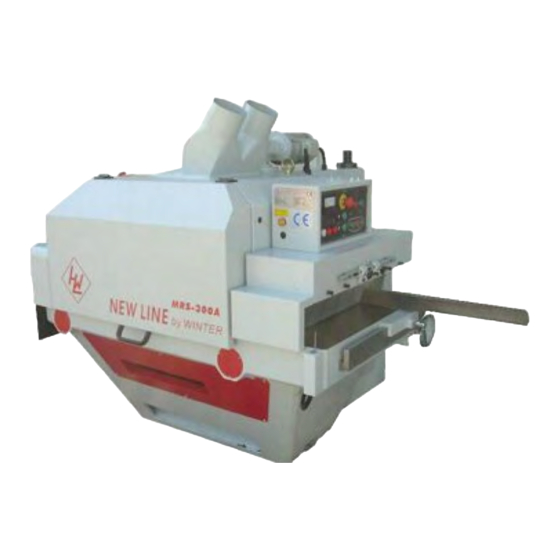
MULTI RIP SAW
WINTER MULTIMAX 300
WARNING!
The operator must thoroughly read this manual before operation.
Keep this manual for future reference.
Henrik Winter Holztechnik GmbH
Druckereistr. 8
04159 Leipzig
Tel: +49 (0)341/ 4619021 Fax: +49 (0)341/4618358 Funk: +49 (0)171/2820443
Em@il: info@winter-holztechnik.de Internet: www.winter-holztechnik.de
Advertisement
Table of Contents

Summary of Contents for Winter MULTIMAX 300
- Page 1 OPERATION MANUAL MULTI RIP SAW WINTER MULTIMAX 300 WARNING! The operator must thoroughly read this manual before operation. Keep this manual for future reference. Henrik Winter Holztechnik GmbH Druckereistr. 8 04159 Leipzig Tel: +49 (0)341/ 4619021 Fax: +49 (0)341/4618358 Funk: +49 (0)171/2820443...
-
Page 3: Specifications
MULTIMAX 300 SPECIFICATIONS SPECIFICATIONS Model NO.: MULTIMAX 300 MULTIMAX 300 Serial NO.: Production date: Drive specifications: Drive Motor Q’TY Volt 1 set □30 □40 □50 □60 Saw arbor motor □2(4/8P) □3(4P) 1 set Feed motor 1 set Pressure rollers elevation motor Belt specifications: □5 □6... - Page 4 MULTIMAX 300 PREFACE PREFACE MRS-300 This manual explains how to install, operate, and maintain the MULTIPLE RIP SAW . Please make certain to read the information contained herein to ensure safe operation and to achieve the longest lifespan and finest results possible.
-
Page 5: Table Of Contents
MULTIMAX 300 CONTENTS CONTENTS CHAPTER 1: INTRODUCTION .................. 1 1-1 SAFETY PRECAUTIONS ..................1 1-2 SPECIFICATIONS TABLE ..................7 1-3 FEATURES ......................8 1-4 LOCATION OF PARTS ..................9 CHAPTER 2: INSTALLATION .................. 13 2-1 PRE-INSTALLATION INSPECTION ..............13 2-2 MOVING THE MACHINE .................. 13 2-3 FIXING THE MACHINE IN POSITION .............. -
Page 7: Chapter 1: Introduction
MULTIMAX 300 Chapter 1: INTRODUCTION CHAPTER 1: INTRODUCTION 1-1 SAFETY PRECAUTIONS A machine of this nature can be dangerous if not used properly, therefore we strongly recommend that the operator comply with the following safety guidelines: The operator must read the operation manual very carefully, before using this machine. - Page 8 MULTIMAX 300 Chapter 1: INTRODUCTION The operator should wear leather gloves and leather apron, and should stand at the side of the machine. Never stand in line with the sawing lines. Never touch, either directly or indirectly, any moving parts of the machine while in operation, or wood which is presently being sawed.
- Page 9 MULTIMAX 300 Chapter 1: INTRODUCTION Planks which are warped lengthwise should be placed with the concave side face down on the caterpillar chain. Suitable circular woodcutting blades should always be used. The blades should be checked regularly for bluntness, crack, and accumulation of sawdust.
- Page 10 MULTIMAX 300 Chapter 1: INTRODUCTION 1-1.1 WARNING PLATES INDICATOR DESCRIPTION DO NOT move unless change saw blade or adjust blade. Make certain that blades are installed with the teeth pointing in the same direction as the rotation of saw arbor turns.
- Page 11 MULTIMAX 300 Chapter 1: INTRODUCTION INDICATOR DESCRIPTION The machine MUST be with the grounding installation below 10 Danger. Warning. Warning. Warning.
- Page 12 MULTIMAX 300 Chapter 1: INTRODUCTION INDICATOR DESCRIPTION Warning. Warning. Operator MUST follows all safety principles and warning stickers on machine.
-
Page 13: Specifications Table
MULTIMAX 300 Chapter 1: INTRODUCTION 1-2 SPECIFICATIONS TABLE Max. cutting thickness (w/o pressure plate) 120 mm Mini. cutting thickness 10 mm Mini. length of workpiece 585 mm Mini. length of workpiece- Option 300 mm Max. cutting thickness (w/ pressure plate) - Option 14"... -
Page 14: Features
MULTIMAX 300 Chapter 1: INTRODUCTION 1-3 FEATURES CATERPILLAR CHAIN WITH VARIABLE FEED SPEED: The caterpillar chain feed mechanism provides extremely accurate straightness and high precision cutting. The feed speed range is 7.5~30 m/min, and is easily adjusted by the handwheel at the stock infeed position. -
Page 15: Location Of Parts
MULTIMAX 300 Chapter 1: INTRODUCTION 1-4 LOCATION OF PARTS 1. Saw arbor front guard 2. Saw arbor elevating handle 3. Holddown roller/housing elevating motor 4. Support rod for saw sleeve 5. Control panel 6. Fence 7. Speed-changing hand-wheel for feeding 8. - Page 16 MULTIMAX 300 Chapter 1: INTRODUCTION Control panel (standard type): 1. Ampere meter 2. Emergent STOP button 3. Blade STOP button 4. Blade START button 5. Power indicator 6. Feed chain lubricant insufficient indicator 7. Protections open indicator 8. Pressure rollers DOWN button 9.
- Page 17 MULTIMAX 300 Chapter 1: INTRODUCTION Control panel (Equip electrical amperage display): (Option) 1. Emergent STOP button 2. Ampere meter 3. Pilot of saw arbor’s load 4. Sensitive adjustment swith of saw arbor’s load 5. Blade star button 6. Blade stop button 7.
- Page 18 MULTIMAX 300 Chapter 1: INTRODUCTION Machine size:...
-
Page 19: Chapter 2: Installation
MULTIMAX 300 Chapter 2: INSTALLATION CHAPTER 2: INSTALLATION 2-1 PRE-INSTALLATION INSPECTION To ensure optimum performance from your machine, the following checks should be made before installation: ◎ Is there any damage to the crate containing the machine? ◎ Does the machine show any signs of having been dropped or mishandled? If the answer to either of these questions is "yes", please contact your dealer... -
Page 20: Fixing The Machine In Position
MULTIMAX 300 Chapter 2: INSTALLATION 2-3 FIXING THE MACHINE IN POSITION 1. PROPER LOCATION FOR THE MACHINE ◎ The floor must be able to support the machine's weight as well as the vibrations produced when it is operating. ◎ The direction of sawed wood coming out of the machine must not be facing an area where people may be passing. -
Page 21: Start-Up Test
MULTIMAX 300 Chapter 2: INSTALLATION 2-5 START-UP TEST After the machine has been installed by following the steps described above and a check has been made to ensure that there are no obstructions surrounding the machine, the following start-up test should be performed: 1. -
Page 22: Connection Of Dust Collecting Apparatus
MULTIMAX 300 Chapter 2: INSTALLATION 2-6 CONNECTION OF DUST COLLECTING APPARATUS Use a 6” dia. flexible hose to connect the two Ø150mm dust outlets to the dust collector. The minimum air consumption for one 6” dia. flexible hose can not be less than 1782 m /hr. -
Page 23: Chapter 3: Operation
MULTIMAX 300 Chapter 3: OPERATION CHAPTER 3: OPERATION 3-1 INSTALL THE PRESSURE PLATE Choose the type of pressure plate according to the length of material to be cut. When the material is over 600mm long, use the normal short pressure plate. When it is less 600mm long, the machine must install with the optional short-stock cutting device. -
Page 24: Installing And Removing Blades
MULTIMAX 300 Chapter 3: OPERATION 3-2 INSTALLING AND REMOVING BLADES There are 2 methods to install or replace the saw blades of the sleeve on the arbor: 1. When saw sleeve is not fixed on the saw arbor: (1) Stand the saw sleeve on the table, then put on proper spacers & saw blades according the cutting-size requested. - Page 25 MULTIMAX 300 Chapter 3: OPERATION (4) Be sure to make the convex part (B in the following picture) of the rear of the saw arbor inserts to the groove (A in the following picture) of the saw sleeve, when put the saw sleeve assembly on the saw arbor.
-
Page 26: Checking Safety Devices
MULTIMAX 300 Chapter 3: OPERATION 2. When the saw sleeve is fixed on the saw arbor: If the saw blades are stayed between the pressure plate, firstly you must lift up the saw arbor and then lower the pressure rollers unit to make the saw blades leave the pressure plate. -
Page 27: Starting The Blades
MULTIMAX 300 Chapter 3: OPERATION 3-4 STARTING THE BLADES Start the saw blades by pressing the saw blades START button. 3-5 FIXING THE SAW ARBOR IN POSITION After the pressure plate and saw blades sleeve assembly have been installed completely, start the saw blades to let the saw arbor rotate. Turn the “saw arbor elevating handle”... -
Page 28: Adjusting The Height Of The Pressure Rollers
MULTIMAX 300 Chapter 3: OPERATION 3-6 ADJUSTING THE HEIGHT OF THE PRESSURE ROLLERS Adjust the pressure rollers (housing) by keeping on pressing the pressure rollers UP or DOWN button until the desired height is reached. The height of pressure rollers pointed on the scale should be less 2~3mm than the real thickness of the wood to be cut. -
Page 29: Adjusting The Position Of The Fence
MULTIMAX 300 Chapter 3: OPERATION 3-7 ADJUSTING THE POSITION OF THE FENCE The fence is positioned by locking handle. There is a distance between the fence and the first saw blade, and the length of this distance is depending on how neat of the edge of the wood to be cut. -
Page 30: Starting The Caterpillar Chain
MULTIMAX 300 Chapter 3: OPERATION 3-8 STARTING THE CATERPILLAR CHAIN Press the feed chain start button-low speed (“turtle” figures 7.5-15M/Min) or the feed chain start button-high speed (“rabbit” figures 15-30M/Min) to make the feed chain move, according to the material and the thickness of the wood, the request on how smooth of cutting face, the sharpness and the number of the blades. -
Page 31: Input Of Material
MULTIMAX 300 Chapter 3: OPERATION 3-9 INPUT OF MATERIAL ◎ To get a precise straight-line ripping, the thickness of wood of four sides should be the same. Badly bent and deformed wood and wood of thickness greater than 110mm should not used. - Page 32 MULTIMAX 300 Chapter 3: OPERATION ◎ According to the quantity and the sharpness of saw blades, feed speed and the smooth demand on the ripping surface, the operator can adjust the sensitivity micro-adjustment button of motor-load to a proper position (to increase the sensitivity by turning it in a clockwise direction;...
-
Page 33: Safety Device For Saw Arbor
MULTIMAX 300 Chapter 3: OPERATION 3-10 SAFETY DEVICE FOR SAW ARBOR This machine has equipped with a safety device which allows the Saw Arbor Cover be opened only when the saw arbor stops completely. When the Saw Arbor starts, it starts the LOCK switch at the same time, and the Saw Arbor Cover can not be opened as well. -
Page 34: Chapter 4: Maintenance
MULTIMAX 300 Chapter 4: MAINTENANCE CHAPTER 4: MAINTENANCE Must disconnect the power of the machine from the power source before doing any maintenance. The operator must obey the following rules to avoid any serious injury. 4-1 CLEANING Regular cleaning of all machine parts and the surrounding environment means greater operating safety and a prolonged machine's life. - Page 35 MULTIMAX 300 Chapter 4: MAINTENANCE ◎ Pay attention to the dust extracting apparatus all the time to ensure the maximum efficiency is being maintained. ◎ At the same time as performing the machine's regular lubrication checks, clean away dust and saw dust from all parts of the machine.
-
Page 36: Lubrication
MULTIMAX 300 Chapter 4: MAINTENANCE 4-2 LUBRICATION Regular lubrication is essential to maintain the long life and optimum performance of the machine. The following inspections should be performed at the time intervals specified and lubrication administered as required. Every day: ◎... - Page 37 MULTIMAX 300 Chapter 4: MAINTENANCE Every 2400-2500 working hours: ◎ After every 2400-2500 working hours, should use a grease gun add grease to the bearings of saw arbors. Before adding grease, the outlet of grease gun should be cleaned completely to avoid impurities entering the bearings with grease.
- Page 38 MULTIMAX 300 Chapter 4: MAINTENANCE 3. Open the feed motor cover, there are 4 grease inlets on the elevating nut of saw arbor. Grease Lubrication Note the following precautions whenever using grease lubrication. ◎ Select the proper grease. For examples of the main types of grease used for machine tool bearings, see Table 4-2.1.
- Page 39 MULTIMAX 300 Chapter 4: MAINTENANCE Table 4-2.2 Bearing Internal Space Volume 1. Internal space volume of angular contact ball bearings and cylindrical roller bearings Unit: cc/each Bore Bore Series diameter diameter 7900C 7000C 7200C BNH000 NN3000 NNU4900 number (mm) 7900AC...
- Page 40 MULTIMAX 300 Chapter 4: MAINTENANCE 2. Ball Screw Support Bearing (TAB Series) Internal Space Volume Internal space Bearing no. volume[cc/each] 15TAB04 17TAB04 20TAB04 25TAB06 30TAB06 35TAB07 40TAB07 40TAB09 45TAB07 45TAB10 50TAB10 55TAB10 55TAB12 60TAB12 3. Ball Screw Support Bearing (TAF Series) Internal Space Volume Internal space Bearing no.
- Page 41 MULTIMAX 300 Chapter 4: MAINTENANCE Figure 4-2.1 Comparison of Temperature Increase Caused by Different Lubrication Methods Changing the oil for the feed chain reduction gears: (use SAE 90# lubricating oil) After 300 working hours, the inside of the feed chain speed-reducer should be cleaned and the oil for the gears should be changed.
-
Page 42: Adjustment And Replacement Of The Saw Arbor Belts
MULTIMAX 300 Chapter 4: MAINTENANCE 4-3 ADJUSTMENT AND REPLACEMENT OF THE SAW ARBOR BELTS A loosening of the machine's transmission belts will inevitably take place after extended use and cause reduced efficiency. In order to minimize wearing of the belts and the loss of machine's power, the belts should be re-tightened by increasing an appropriate distance between the saw arbor pulley and the motor pulley. -
Page 43: Inspection And Replacement Of The Variable Speed Belt
MULTIMAX 300 Chapter 4: MAINTENANCE 4-4 INSPECTION AND REPLACEMENT OF THE VARIABLE SPEED BELT If vibrating sounds can be heard emanating from the variable speed pulley, the outer metal cover should be removed and the variable speed pulley should be examined. - Page 44 MULTIMAX 300 Chapter 4: MAINTENANCE The method of adjustment: The tension of belts is adjusted by the 3 nuts as shown in the picture (uses 2 pcs of 19mm open-end wrench as tools). The new belts should be re-tightened after the first 4 working hours.
-
Page 45: Adjusting The Oil Supply To The Caterpillar Chain
MULTIMAX 300 Chapter 4: MAINTENANCE 4-5 ADJUSTING THE OIL SUPPLY TO THE CATERPILLAR CHAIN 1. There are 2 adjustment knobs on the lubricator. The upper knob is for adjusting the interval time between the two lubrications (minute), the lower knob is for adjusting the lubrication time / per pump (second). -
Page 46: Appendix І: Installation And Adjustment Of Pressure Plate
TIMAX 300 Appendix I: Installation and Adjustment of Pressure Plate Appendix І: Installation and Adjustment of Pressure Plate 1. Install and adjust the short pressure plate: : : : (1) Firstly, take off the long pressure plate and the pressure plate fixed support from the housing. - Page 47 MULTIMAX 300 Appendix I: Installation and Adjustment of Pressure Plate (4) Adjust the set screws (total 3 pcs) that locate on the pressure plate fixed support to make the lowest position of the pressure plate to be apart from the machine table for 37mm.
- Page 48 MULTIMAX 300 Appendix I: Installation and Adjustment of Pressure Plate 2. Install and adjust the long pressure plate: (OPTION) (1) Arise the pressure roller housing to a proper height (80mm). (2) Take off the left and right shields, and the short pressure plate.
- Page 49 MULTIMAX 300 Appendix I: Installation and Adjustment of Pressure Plate (5) Lock the long pressure plate to both the rear mounting bracket of pressure plate and the pressure plate fixed support. (6) Descend the pressure roller housing to “zero” position (go home).
- Page 50 MULTIMAX 300 Appendix I: Installation and Adjustment of Pressure Plate (8) Then, adjust these 4 pcs of nuts until the long pressure plate is away from the surface of feed chain for about 1mm (near to the thickness of a steel ruler).
- Page 51 ULTIMAX 300 Appendix I: Installation and Adjustment of Pressure Plate The pressure plate must be made of solid and complete wood according the following diagram: (optional)
- Page 53 BM31-03-0 PAGE:...
- Page 54 BM31-05-0 BM31-05-0 PAGE: BM31-05-0 BM31-05-0...
- Page 55 BM31-10-0 PAGE:...
- Page 56 AM31-010-0 PAGE:...
- Page 57 AM31-020-0 PAGE:...
- Page 58 AM30C-121-0 PAGE:...
- Page 59 AM30C-130-1 AM30C-130-1 AM30C-130-1 AM30C-130-1 PAGE:...
- Page 60 AM31-100-0 PAGE:...
- Page 61 AM31-121-0 PAGE:...
- Page 62 AM12-100-0 PAGE:...
- Page 63 BM30C-210-0 BM30C-210-0 BM30C-210-0 BM30C-210-0 PAGE:...
- Page 64 BM30C-231-0 BM30C-231-0 BM30C-231-0 BM30C-231-0 PAGE:...
- Page 65 MRS-300C MRS-300C MRS-300C MRS-300C MODEL: BM30C-240-0 BM30C-240-0 BM30C-240-0 BM30C-240-0 PAGE:...
- Page 66 BM31-26-0 PAGE:...
- Page 67 AM30C-030-0 PAGE:...
- Page 68 AM30C-040-3 AM30C-040-3 AM30C-040-3 AM30C-040-3 PAGE:...
- Page 69 AM30C-050-1 AM30C-050-1 AM30C-050-1 AM30C-050-1 PAGE:...
- Page 70 AM30C-080-0 AM30C-080-0 AM30C-080-0 AM30C-080-0 PAGE:...
- Page 71 AM30C-110-0 PAGE:...
- Page 72 AM30C-150-0 AM30C-150-0 AM30C-150-0 AM30C-150-0 PAGE:...
- Page 73 11 2 AM30C-261-0 PAGE:...
- Page 74 AM31-303-0 PAGE:...
Need help?
Do you have a question about the MULTIMAX 300 and is the answer not in the manual?
Questions and answers