Table of Contents
Advertisement
Quick Links
Advertisement
Table of Contents

Subscribe to Our Youtube Channel
Summary of Contents for Explorer Group DLV40
- Page 1 Operator’s Manual: Operator’s Manual: Operator’s Manual: DLV40 Data logging Voltmeter 40 Data logging Voltmeter 40 Data logging Voltmeter Rev: 02 Date: 5/28/2012 DLV40 Firmware: Rev 000.008 and above Winmeter 5.0 Software: Rev 1.0.0 and above...
-
Page 2: Table Of Contents
Over Voltage Indication (ALL Modes) Recording Over a Previous Measurement (ALL Modes) Deleting a Previous Measurement (ALL Modes) Discharge Test Procedure Step1: Select DLV40 “Discharge Test” Mode & Clear Existing Test Data 5.1.1 Option 1: Using Winmeter 5.0 Software 5.1.2... - Page 3 Float Test Procedure (“8x256” and “20x48” Modes) Step1: Select DLV40 “8x256” /“20x48” Mode & Clear Old String Data 6.1.1 Option 1: Using Winmeter 5.0 Software 6.1.1 Option 2: Manually Step 2: Measure String Float Cell Voltages Step 3: Upload “8x256/20x48” Test Data to Winmeter 5.0...
-
Page 4: Overview
The DLV40 is capable of operating in (3) distinct measuring modes: “8 by 256” Mode: The DLV40 can measure and store up to 2048 readings of cell voltage. These readings are stored in 8 separate data strings of 256 readings, denoted A through H. -
Page 5: User Interface
User Interface 1.1.1 Graphical Back lit LCD Display (128x32) Discharge Time Current measurement (Currently 3 seconds mode. into the test). Dischg 0:00:03 +0.000 Selected String (“B”) and B:001 000.0 Sum of cell voltages the next reading in the for the selected selected string (“001”). -
Page 6: Menu System
2.0 Menu System The DLV40 uses a simple two tier menu system. The “Main Menu” and (3) sub-menus, one for each measurement mode (“8 by 256”, “20 by 48” and “Discharge Test”). Main Menu “MENU” Button: When the DLV40 is in one of the measurement modes, push the MENU button once to enter the appropriate sub-menu, push the MENU button a second time to enter the Main Menu. - Page 7 2.2 “Discharge” Sub-Menu Discharge Test Mode *** Discharge Menu*** *** Discharge Menu*** (Please refer to section X.X for Delete B:003? Reading Deleted more information) Discharge Test Mode *** Discharge Menu*** (Please refer to Section 5.0 for the Exit? Discharge Test Procedure Start/Delete Discharge Test lease refer to section X.X (Start) *** Discharge Menu***...
- Page 8 2.3 “20 by 48” Sub Menu 20 x 48 Test Mode *** 20 x 48 Menu *** *** 20 x 48 Menu*** (Please refer to section X.X for Delete J:025? Reading Deleted more information) 20 x 48 Test Mode *** 20 x 48 Menu*** (Please refer to Section 6.0 for Exit?
- Page 9 2.4 “8 by 256” Sub Menu 8 x 256 Test Mode *** 8 x 256 Menu *** *** 8 x 256 Menu*** (Please refer to section X.X for Delete A:025? Reading Deleted more information) 8 x 256 Test Mode *** 8 x 256 Menu*** (Please refer to Section 6.0 for Exit?
- Page 10 (ii) Select the required measurement mode (“20x48”, “8x256” or “Discharge”). When turned ON, the DLV40 will automatically resume in the previous mode and “point” to the next reading location. (Please refer to section X.X for Mode selection for more information) (iii) Select required string.
- Page 11 Remove the voltage probes from the cell terminals. The reading is held on the display until the probes are removed. After approximately (1) second the DLV40 stores the reading, adds the reading to the sum of string cell voltages and increments to the next reading.
- Page 12 Section 5.0 to for the Discharge Test Procedure Over Voltage Indication (ALL Modes) The DLV40 provides both an audio and visual indication if the probes are connected to an excessive input voltage (Vin < -19.999 VDC or Vin > +19.999 VDC)
- Page 13 (Shows 046.6 if (20) ~ selected location (“003”). 2.3 VDC readings have been stored). (ii) The currently stored reading is shown for approximately (2) seconds then the DLV40 reverts to measurement mode. Current measurement 8x256 mode. +0.000 Sum of cell voltages for Selected String (“B”) and...
- Page 14 046.6 VDC readings have been the current reading in the stored). selected location (“003”). (ii) The currently stored reading is shown for approximately (2) seconds then the DLV40 reverts to measurement mode. Current measurement 8x256 mode. +0.000 Sum of cell voltages for Selected String (“B”) and...
-
Page 15: Main Menu
Auto-off (10) Note: If a “Discharge Test” has been started, the DLV40 will continue to measure the time elapsed since the discharge test was started. In ALL modes, when turned ON the DLV40 will automatically start in the previous mode and “point”... - Page 16 (iii) Press “ENTER” to select. DLV40 Rev: 000.008 9-15-11 12:30:21 Battery 95% Cal: 6-15-11 (iv) Press “MENU” to return to the main Menu.
-
Page 17: Discharge Test Procedure
If the “DLV40 & DMA35 USB Interface” does not initiate automatically select “Download Device” -> “Via USB (search for device)”. (ii) Once connected, the DLV40 will display “DLV40 <-> PC” and download data in its current mode Change mode of... - Page 18 If the DLV40 is NOT in “Discharge Test” mode, the User can change to “Discharge Test” mode by the selecting the “Charge/Discharge Test” radio button. Select Charge/Discharge Test mode Changing the DLV40 mode will cause the DLV40 to refresh data.
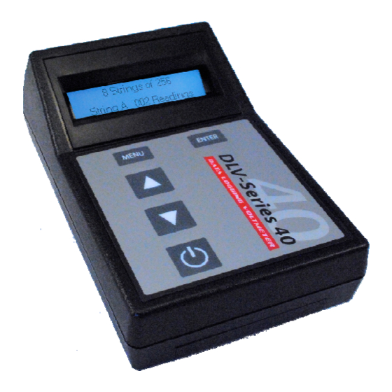
- Page 19 Turn the DLV40 ON. The DLV40 must NOT be connected to the PC via USB! Upon start-up the DLV40 will display the model number & firmware revision, the current date and time and then the current test mode: - “8 string of 256”, “8x256” in top left hand corner.
- Page 20 String A : 010 Readings As shown, String A contains 10 readings and hence there is existing Discharge Test data and the DLV40 is not ready to start a new discharge test. See below for instruction on deleting ALL existing discharge test data.
- Page 21 C. Press “ENTER” to select. ** Discharge Menu ** Deleting A: 05% The DLV40 will now delete ALL (8) discharge test strings (A->H) This process will take approximately 8 seconds.
-
Page 22: Step 2: Measure String Float Cell Voltages
(“000”). If any previous discharge test data had been deleted then the DLV40 display should match that shown below. If not, please erase ALL previous data (see Step 1 above). Connect voltage measurement probes to DLV40 and measure float cell voltages ensuring that the cell number of the next reading matches with the cell number counter in the bottom left hand corner of the display. - Page 23 For example, after taking 10 cell float voltage readings of average ~ 2.45 the DLV40 display should match the above. Note: The DLV40 may be turned OFF and ON while cell voltage readings are being taken. When turned ON, it will automatically start in the previous mode...
- Page 24 Step 3: Start the Discharge Test Timer & Take Up to (7) Sets of Cell Discharge Readings Ensure the DLV40 USB cable is DISCONNECTED The DLV40 USB cable MUST be DISCONNECTED whenever measuring voltages! (ii) Turn the DLV40 ON. (iii) If NOT in “Discharge Test”...
- Page 25 The DLV40 may be turned OFF and ON after the Discharge Test has been started. It will also automatically turn OFF after ~3 minutes of inactivity. While OFF, the DLV40 will continue to measure the time elapsed since the discharge test was started.
- Page 26 For example, after taking the first (5) cell discharge voltage readings of average ~ 2.35 the DLV40 display should match the above. The DLV40 may be turned OFF and ON after the Discharge Test has been started. While off, the DLV40 will continue to measure the time elapsed since the discharge test was started.
- Page 27 When the number of readings in String B matches the number of float readings in String A (the User has completed the first set of cell discharge readings) the DLV40 automatically increments to String C. Next String! Discharge Time (showing 12 minutes...
-
Page 28: Step 4: Upload Discharge Test Data To Winmeter
Change mode of discharge data. operation (if required). If the DLV40 is NOT in “Discharge Test” mode, the User can change to “Discharge Test” mode by the selecting the “Charge/Discharge Test” radio button. DLV40 DLV40 Changing the mode will cause the to refresh data. -
Page 29: Step 5: Generate Cell Discharge Report(S)
Step 5: Generate Cell Discharge Report(s) Database parameter Optional report remains blank until information and report is saved. parameters Optional User notes Data grid of Cell Discharge Data (“Click” cells to edit) Report filename or status if “unsaved” Add report information and parameters (all optional): Report Title Technician Name Battery Type... - Page 30 (iii) Generate Selected Report (Optional): Select up to 4 cells (including average cell data) and click the “Selected Report” button. The User can generate multiple reports, selecting a different combination of cells each time. To save the report to Excel or PDF format, click the ”Save As”...
- Page 31 (iv) Generate General Report (Optional): Click the “General Report” button. To save the report to Excel or PDF format, click the “Save As” icon in the Report header.
- Page 32 Export Data to Excel (Optional): Click the “Export to Excel” button. Including report information and parameters is OPTIONAL The User will be prompted to include/exclude report parameters and to enter a file name.
-
Page 33: Step 6: Save Cell Discharge Report(S)
Step 6: Save Cell Discharge Report(s) Click the “Save” button to save the cell discharge test report into the Winmeter 5.0 battery database. Select an existing customer directory or “<add new>” to add a new customer directory into the Winmeter 5.0 database. (ii) Select an existing string directory or “<add new>”... - Page 34 The Discharge Test is now saved. Database parameters of Optional report saved file. information and parameters. Optional User notes Data grid of Cell Discharge Data (“Click” cells to edit). Report filename The discharge test file is now saved into the Winmeter 5.0 database and the User can safely “Close”...
- Page 35 Once connected, the DLV40 will display “DLV40 <-> PC” and download data in its current mode . Change mode of operation . (If required) If the DLV40 is NOT in the required mode, the User can change to “8x256” or “20x48” mode by the selecting the appropriate radio button.
- Page 36 Select “8x256” or “20x48” mode as required . Changing the DLV40 mode will cause the DLV40 to refresh data. (vii) Once in “8x256” or “20x48” mode: (A) Select any/all strings (“8x256” mode A->H, “20x48” mode A->T) that contain obsolete data.
- Page 37 Turn the DLV40 ON. The DLV40 must NOT be connected to the PC via USB! Upon start-up, the DLV40 will display the model number & firmware revision, the current date and time and then the current test mode: - “8 string of 256”, “8x256” in top left hand corner.
- Page 38 To change the current measurement string (“8x256” mode A->H, “20x48” please refer to section X.X for instructions on changing the mode A->T), selected string within a mode. Current Test Mode 8x256 +0.000 A:011 023.5 Sum of cell voltages Selected String (“A”) for the selected string and next reading in the selected string (“010”)
- Page 39 Delete String: ** 8 x 256 Menu ** Delete String B ? C. Press “ENTER” to select. ** 8 x 256 Menu ** Deleting B: 05% The DLV40 will now delete string B. This process will take approximately 1 second.
- Page 40 The DLV40 USB cable MUST be DISCONNECTED whenever measuring voltages! Turn the DLV40 ON. (ii) Ensure that the DLV40 is in the correct mode, required string is selected and all previous string data has been deleted. Current Test Mode 8x256 +0.000...
- Page 41 Click “Done” to begin the discharge report generation process. If the DLV40 is NOT in the required mode (“8x256” or ”20x48”), the User can easily change modes by selecting the required radio button. DLV40 DLV40 Changing the mode will cause the to refresh data.
- Page 42 (iii) Add Hydrometer Data (Optional - “8 by 256” Mode ONLY) To add hydrometer data from a DSG30 or DMA35(n) data logging module: Connect the companion instrument (DSG30 or DMA35 data logging module) to PC via RS232 cable. Turn companion instrument ON. Click the “Import HYD Data Via RS232”...
- Page 43 Step 4: Select Float String to Save Select the first save. Strings are saved one at a time. add report parameters and save the report. (ii) Click “Save” to Strings “I” through “J” are ONLY enabled in “20 by 48” Voltage only mode 6.4.1 Preview String Data (Optional) to preview selected string data with statistics.
- Page 44 Step 5: Generate Cell Float Report(s) 6.5.1 Add/Edit Report Information and Parameters Database Data summary parameter blank until report is saved. Optional User Data grid of Cell editable report Discharge Data parameters. (Click cells to edit). Optional User notes Report filename or status if “unsaved”.
- Page 45 6.5.2 View/Print Report(s) For “20 by 48” Voltage only data the “Graph” button is disabled and the “Report” button will generate a combined graph and tabular report. 6.5.2.1 Graph Click “Graph” to produce a graph report.
- Page 46 6.5.2.2 Tabular Report Click “Report” to produce a tabular report 6.5.2.3 Saving Report to PDF or Excel Format To save a report to Excel or PDF format, click the “Save As” icon in the Report header.
- Page 47 6.5.3 Export Data to Excel (Optional) Click the “Export to Excel” button. Including report information and parameters is OPTIONAL. The User will be prompted to include report parameters and to enter a file name.
- Page 48 Step 6: Save Cell Test Report(s) Click the “Save” button to save the cell float test report into the Winmeter 5.0 battery database. Select an existing customer directory or “<add new>” to add a new customer directory into the Winmeter 5.0 database. Next, select an existing string directory or “<add new>”...
- Page 49 Database Data summary parameters no longer blank as report is saved. Optional User Data grid of Cell editable report Discharge Data parameters (“Click” cells to edit) Optional User notes Report filename displayed as report now saved. The float test file is now saved into the test database and the User can safely close the Winmeter 5.0 software.
- Page 50 7.0 Connecting the DLV40 to PC/Winmeter 5.0 (iv) Connect the DLV40 to a PC (via USB cable) with Winmeter 5.0 software installed. If the Winmeter 5.0 Auto-start software is not enabled, RUN the Winmeter 5.0 Software. If the “DLV40 & DMA35 Module USB Interface” does not initiate automatically select “Download Device”...
- Page 51 Device Interface Status Current firmware revision (000.008) Once connected, the DLV40 connection status and current firmware revision will display in the footer of the appropriate Interface window. (ii) Click the “Setup” button to start the firmware update process.
- Page 52 (iii) Click “Cancel” to close the window and return to the DLV40 Interface window. Click “Update Firmware” to place the Device into “Bootloader Mode” and run the Device Bootloader software. Bootloader Mode! Fig 11.1 : DLV40 in Bootloader Mode DLV40 Bootloader Software (iv) Click “Open Hex File”...
Need help?
Do you have a question about the DLV40 and is the answer not in the manual?
Questions and answers