
Related Manuals for Funk Amateur FA-VA4

Summary of Contents for Funk Amateur FA-VA4
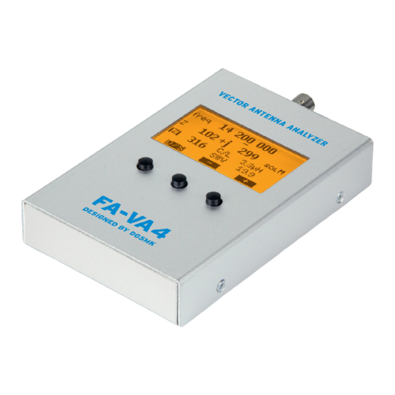
- Page 1 Vector Antenna Analyzer FA-VA4 Kit for an easy to use vector antenna analyzer for use in the frequency range 100 kHz to 100 MHz. Construction and User Manual...
- Page 2 100 kHz to 100 MHz with a system impedance of 50 Ohms. Experimenting with antennas is an essen- Vector measurement means that in con- The FA-VA4 kit consists of an SMD tial part of the hobby for many radio ama- trast to a scalar measurement, not only is mounted circuit board, the graphics dis- teurs.
-
Page 3: Building Instructions
Building instructions Mounting the board Fig. 2 shows the layout plan with the few For construction, the following tools and – Flat nose pliers, components still to be soldered. These are equipment will be required. – Slot screwdriver, to be mounted exclusively on the upper –... - Page 4 (Fig. 3). The simplest way to do this is to make a provisional solder connection us- ing one solder tag on the switch thus al- lowing for correct alignment whilst heat- ing the solder. When it is in the correct position all the connector tags for the switch along with the two for the housing may be soldered.
- Page 5 display after which the whole assembly, display and sockets, must be placed onto the board. The thin ends of the solder tags are pushed fully into their respective holes taking care not to press too hard and that the tags aren't pushed too deep into their holes.
- Page 6 Should the display remain blank derside of the device. then all the previous soldering must be Your FA-VA4 is ready now and can be checked and reworked if necessary. When used in an uncalibrated measuring mode. everything is working correctly the slider switch should be turned off and the batter- ies removed from their holder.
- Page 7 BNC plugs should be carefully twisted af- Rechargeable batteries should not be display cannot be read. With daylight or ter connecting to ensure no ‘unexpected’ used in the FA-VA4 as no deep discharge outside the display doesn't usually needs incorrect measurements.
-
Page 8: Directions For Use
Directions for use Although the FA -VA4 has a relatively electrical properties of the object under The middle and right buttons then allow wide range of functions, its operation is test, the signal will be changed in both am- you to select a menu item which may then fairly intuitive therefore the following plitude and phase. - Page 9 The analyzer knows two different modes of SOL compensation. Calibration (SOL compensation) Every extra plug and additional piece of cable influences the impedance measure- ment of the test object. This unwanted in- It is possible to permanently save SOL ref- SOL for all frequencies fluence can be completely compensated erence values for the entire measuring...
- Page 10 of single frequency calibration the display solf will show , in case of no calibration at SOL for an individual frequency sol- For all individual frequency measure- all it will show ments it is possible to run through SOL compensation for the actual frequency, (Operating Mode Æ...
- Page 11 Options in the menu Setup ratio (SWR), the effective impedance re- sistance (Formula Z), the impedance reac - Table 3: FA-VA4 Setup mode tance (+j/ j), the SWR shown as a bar graph Menu item Meaning...
- Page 12 The actual measurement frequency can be set using the three push buttons. The left button (D/S) selects the decimal place in- dicated by an underscore line. With the middle or right hand button the values may be increased (+) or decreased (–). For an eventual compensation (SOL One Frequency) the corresponding function in the operation mode menu must be select-...
- Page 13 centre frequency can be increased or de- creased by some 100 kHz. At the same Single frequency impedance time, each button press triggers a new measurement measurement cycle over the defined fre- Displayed are the actual measurement fre- quency range. quency (freq.) the complex impedance af- >...
- Page 14 contrast to the < and > mode, no new measurement cycle is triggered by but- Single run for impedance ton pressing, only the changed marker measurement position, including the corresponding The active resistance (solid curve) and the measured value, is displayed. The mea- reactance (dashed curve) are shown above sured values determined before switch- the frequency.
- Page 15 Unoc- cupied memory locations are displayed completely empty. The left button D/S al- The FA-VA4 now operates as an RF gen- lows you to return to the previous test HF Generator Fig. 24: Display view using the FA -VA4 as sig- erator with a square wave signal output at mode (Fig.
- Page 16 This is repeated up to frequency f (Fig. 26). Setup Mode The following settings options are includ- Having confirmed the last frequency the ed in a separate menu as they are rarely analyzer returns to the previous test mode. used in practice. They are accessible via Operating Mode Æ...
- Page 17 FA-VA4 will take the set value as the frequency Display Lighting The possibilities are On, Off, and Auto. correction amount. Now the frequency of With the automatic option the lighting will the analyzer output signal should corre- turn off after a time, turning on again after spond exactly to the set value.
- Page 18 Forced Reset (without menu item) Display Update Cycle For individual frequency measurements In the unlikely event of the device becom- there are three options available, Slow, ing unresponsive even when switched off Medium and Fast. The selection has no and on again, a forced reset can be carried influence on the measuring accuracy but out without recourse to the menu.
- Page 19 Measurement of Antenna Impedance Tips on measurements in Multi Frequency Measurement of and SWR for a single frequency practice Impedance and SWR of an Antenna The application possibilities of measuring The antenna is connected directly to the The antenna is connected directly to the a complex impedance are very diverse.
- Page 20 If a signal generating source (in our case short circuited. When the cable end is For example RG58 co ax cable has shorten- FA-VA4 as a Dip Meter the analyzer) is loosely coupled in parallel open, points of resonance occur at ing factor of 0.66 so the propagation speed...
- Page 21 onant frequency of a cable is determined Literature and References: from the previous section, the physical [1] Knitter, M., DG5MK: 100 MHz antenna vector length can be determined by using the analyzer for everyone. FUNKAMATEUR 66 above equation and the shortening factor (2017) H.
- Page 22 Parts list Appendix Abbreviation Part description Quantity Note BNC socket S1 … S3 Pushbutton switches (S1 … S3) Knobs for pushbuttons Slider switch G1, G2 AA Battery holders Graphic display with backlight preassembled 20 pin connector or 2 10 pin for display 3 pin connector for display SMD mounted circuit board...
- Page 23 Box 73 Amateurfunkservice GmbH When disposing of this product, please observe the regulations Majakowskiring 38 for the handling of electronic waste. Electronic devices, batteries 13156 Berlin and components do not belong in household waste. For further www.funkamateur.de · www.box73.de www.box73.com Status July 2017 information see www.box73.de...
Need help?
Do you have a question about the FA-VA4 and is the answer not in the manual?
Questions and answers