Table of Contents
Advertisement
User Guide
GenPro 2xe
GenPro 22e
(GenPro 20e AOB)
Référence : EG_GenPro2xe_1003_UG_005_UK
Révision :
Date :
S.A. ERCO & GENER – ZI de St. Lambert-des-Levées – BP 30163 – F-49412 SAUMUR Cedex
Tél. : +33 (0)2 41 83 13 00 – Fax : +33 (0)2 41 67 19 20 – www.ercogener.com – infos@ercogener.com
€
SA CAPITAL 200873
– R.C. SAUMUR B 332 174 820 – SIRET 332 174 820 00032 – NAF 2630Z – TVA Intra : FR 16 332 174 820
GenPro 23e
005
02/03/2012
L'esprit Modem
(GenPro 24e AOB)
Dct_427_00
Advertisement
Table of Contents

Summary of Contents for Erco & Gener GenPro 22e
- Page 1 L’esprit Modem User Guide GenPro 2xe GenPro 22e GenPro 23e (GenPro 20e AOB) (GenPro 24e AOB) Référence : EG_GenPro2xe_1003_UG_005_UK Révision : Date : 02/03/2012 S.A. ERCO & GENER – ZI de St. Lambert-des-Levées – BP 30163 – F-49412 SAUMUR Cedex Tél.
- Page 2 EG_GenPro2xe_1003_UG_005_UK Page 2 / 63 Document History Rev. Modifications Author Date Validation Date CREATION 11/08/2010 Add 4-wire cable with mini Blade fuse § 2.1 Contents and § 3.2.2.1 4-wire micro FIT Updating - of the limit of use of the digital input du § 8.2.3.1 Opto-coupled Inputs - of the environmental conditions for the use with battery option.
-
Page 3: Table Of Contents
3.2.1.2 Micro FIT connectors ......................16 3.2.1.3 15-pin Sub D HD connector ....................17 3.2.2 Cables ............................18 3.2.2.1 2-wire micro FIT cable GenPro 22e ..................18 3.2.2.2 4-wire micro FIT cable GenPro 23e ..................18 ... - Page 4 EG_GenPro2xe_1003_UG_005_UK Page 4 / 63 6.3 "NO CARRIER" ........................... 34 MESSAGE 7 FUNCTIONAL DESCRIPTION ........................35 7.1 A ............................35 RCHITECTURE 7.2 P ............................35 OWER SUPPLY 7.2.1 General presentation ........................35 7.2.2 Internal battery option ........................36 ...
-
Page 5: Eg_Genpro2Xe_1003_Ug_005_Uk
EG_GenPro2xe_1003_UG_005_UK Page 5 / 63 DECLARATION OF CONFORMITY ....................... 63 Descriptions and non-contractual illustrations in this document are given as an indication only. ERCO&GENER reserves the right to make any modifications. Dct_427_00... -
Page 6: Eg_Genpro2Xe_1003_Ug_005_Uk
The GenPro 2xe is a robust, reliable and long life product. Its very compact metal case makes it ideally adapted to onboard standards The range GenPro 2xe comes in two versions: GenPro 22e and GenPro 23e Optional back-up battery and accelerometer associated with EGM (Erco & Gener Middleware) development... -
Page 7: Avertissement
EG_GenPro2xe_1003_UG_005_UK Page 7 / 63 Avertissement • Erco&Gener advises to read carefully all the documents concerning the GenPro 2xe (User Guide, Application Notes, Command List). • ERCO & GENER cannot be held responsible for: The problems due to an inappropriate use of the GenPro 2xe . The problems due to a wrong configuration The problems due to a wrong use of an embedded software application developed or supplied by a third party. -
Page 8: Copyright
The reproduction, transfer, distribution or storage of part or the totality of the contents of this document, in any form, without the prior written authorization of ERCO & GENER is strictly prohibited. GenPro 22e and GenPro 23e are a trademark of ERCO & GENER. -
Page 9: Various References
EG_GenPro2xe_1003_UG_005_UK Page 9 / 63 1 Références 1.1 Various References The functionality according to the references GenPro 2xe are summarized in the table below Modem GenPro 2xe GSM Functions - E-GSM Quad-Bandes 850/900/1800/1900 MHz - ETSI GSM Phase 2+ Classe 4 (2W @ 850 / 900 MHz) Classe 1 (1W @ 1800 / 1900 MHz) - SIM Toolkit Release 99 Voice Functions... -
Page 10: Referred Documents
EG_GenPro2xe_1003_UG_005_UK Page 10 / 63 1.2 Referred documents Commands List of Standard library of ERCO & GENER : EG_EGM_CL_xxx_yy the embedded application EasePro of ERCO & GENER : EG_EasePro_01_CL_xxx_yy Application Notes GenPro 2xe of ERCO & GENER : EG_GenPro2xe_1003_AN_xxx_yy GSM reference documents: ●... - Page 11 EG_GenPro2xe_1003_UG_005_UK Page 11 / 63 GPRS General Packet Radio Service Global Positioning System Global System for Mobile communications Half Rate Input International Electrotechnical Commission IMEI International Mobile Equipment Identification Input / Output Light Emitting Diode Low Level Command MAXimum Mobile Equipment MICrophone Micro FIT Family of connectors from Molex...
-
Page 12: Symbols
EG_GenPro2xe_1003_UG_005_UK Page 12 / 63 1.4 Symbols The following symbols are used to highlight the important information of this userguide. A symbol for the essential information concerning the module integration and performance. A warning symbol indicates the actions that could harm or damage the module. 2 Packaging 2.1 Content The GenPro 2xe (see table 1.1) is supplied with:... - Page 13 EG_GenPro2xe_1003_UG_005_UK Page 13 / 63 Depending on the reference GenPro ordered, 2 or 4 wires cables are supplied. Descriptions and non-contractual illustrations in this document are given as an indication only. ERCO&GENER reserves the right to make any modifications. Dct_427_00...
-
Page 14: Packing Case
EG_GenPro2xe_1003_UG_005_UK Page 14 / 63 2.2 Packing case The external dimensions of the packing case are: - Width: 54.5 mm, - Height : 68 mm, - Length: 108 mm. An identification label is put on the top of the packing case. It shows: - The ERCO &... -
Page 15: General Presentation
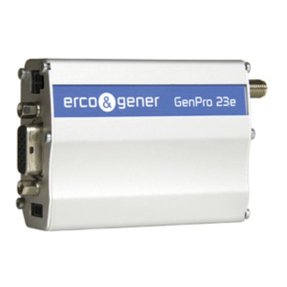
EG_GenPro2xe_1003_UG_005_UK Page 15 / 63 3 General Presentation 3.1 Description Description of the modem GenPro 2xe : Micro-Fit 2pts/M Connectorr Micro-Fit 4pts/M (only GenPro 23e connector Sub HD 15pts/F Connector Front side Rear side SMA/F Connecteur SIM card cover GSM LED 2 brackets to fix the modem on a support. -
Page 16: External Connections
This connector GenPro 2xe is a connector for external power DC and GPIO (these 2 Input and output signals are available only for the GenPro 24e version). Signal Pin N° GenPro 22e GenPro 23e +VDC +VDC INPUT 1(E1) OUTPUT (S1) The pins 3 and 4 are used for the Input/Output functions. -
Page 17: 15-Pin Sub D Hd Connector
EG_GenPro2xe_1003_UG_005_UK Page 17 / 63 3.2.1.3 15-pin Sub D HD connector The female 15-pin high density Sub D connector is used for: - The RS232 serial link connection, - The audio line connection (microphone and loud-speaker), - The BOOT and RESET signals. Description Pin N°... -
Page 18: Cables
Page 18 / 63 3.2.2 Cables According GenPro ordered, different cables described below will be delivered (refer to table 1.1). 3.2.2.1 2-wire micro FIT cable GenPro 22e The 2-wire micro FIT cable allows to power the modem. Molex connector 5mm tinned copper wire... -
Page 19: 2-Wire Micro Fit Cable Genpro 23E
EG_GenPro2xe_1003_UG_005_UK Page 19 / 63 Component Characteristics 4-pin Micro FIT connector Cable Length ≈ 1.5m Wire Tinned copper 24 x 0.2 mm Surface area : 0.75 mm² Fuse mini N 2A 32V Fast (Grey) 3.2.2.3 2-wire micro FIT cable GenPro 23e The 2-wire micro FIT cable allows to use the 2 supplementary inputs. -
Page 20: Characteristics And Services
EG_GenPro2xe_1003_UG_005_UK Page 20 / 63 4 Characteristics and Services The GenPro 2xe is a class10 GSM/GPRS modem dedicated to asynchronous binary data transmission, SMS and voice. It may also have 3 inputs and 1 output The characteristics of different GenPro 2xe are summarized in the table in paragraph 1.1 The available services are summarized in the table below. -
Page 21: Installation Of The Modem
EG_GenPro2xe_1003_UG_005_UK Page 21 / 63 5.1.2 Installation of the modem To install the modem, it is recommended to do the following operations with the modem turned off: - Remove the SIM card cover on the rear side. - Carefully insert the SIM card into the reader. Way of insertion of the SIM card - Push the SIM card until hearing a "clic"... -
Page 22: Checking The Communication With The Modem
EG_GenPro2xe_1003_UG_005_UK Page 22 / 63 The modem is now ready. There are different cases depending on the application or library installed inside the equipment: - Without library: corresponds to the Boot_Loader. - With EGM standard library. - The application ERCO & GENER EasePro-01. - The owner application.. -
Page 23: Standard With Egm Library
EG_GenPro2xe_1003_UG_005_UK Page 23 / 63 5.1.3.2 Standard with EGM Library The GenPro 2xe contains the EGM standard library; it is waiting for a command. Connect the link RS232 between the DTE (COM port) and the modem (DCE). Set the RS232 port of the DTE as follows: ▪... -
Page 24: Sim Card Extraction
EG_GenPro2xe_1003_UG_005_UK Page 24 / 63 5.1.4 SIM card Extraction To remove the SIM card from the modem, it is recommended to do the following operations with the modem turned off: - Remove the SIM card cover on the rear side. - Press the SIM card (simple pressure) until hearing a "clic"... -
Page 25: Specific Recommendations For The Use Of The Modem In Vehicles
EG_GenPro2xe_1003_UG_005_UK Page 25 / 63 5.2 Specific recommendations for the use of the modem in vehicles The power supply connector of the modem GenPro 2xe must NOT be connected directly to the battery of the vehicle. 5.2.1 Recommended Connection on the battery of a truck All lorries have a Circuit Breaker outside the cabin. -
Page 26: Technical Constraints In Truck
EG_GenPro2xe_1003_UG_005_UK Page 26 / 63 5.2.2 Technical constraints in truck It is highly recommended NOT to connect the modem supply directly to the battery but to the circuit breaker. Otherwise the modem can be damaged when the lorry is starting up if the circuit breaker is closed (in this case, the ground of the lorry and the ground of the battery will be connected via the modem as described in the scheme below) GenPro 2xe... -
Page 27: Modem Leds
EG_GenPro2xe_1003_UG_005_UK Page 27 / 63 5.3 Modem leds 5.3.1 Without library The GenPro 2xe does not contain any library. The led is off. 5.3.2 With EGM standard library The led remains off. 5.3.3 The application ERCO & GENER EasePro-01 This application is currently under development. Contact us. 5.3.4 The owner application The GenPro 2xe contains your application. -
Page 28: Checking The Quality Of The Gsm Reception Signal
EG_GenPro2xe_1003_UG_005_UK Page 28 / 63 5.5 Checking the quality of the GSM reception signal The modem contains the EGM standard library (see the documents "EG_EGM_CL_xxx_yy" of ERCO & GENER) in this case, the modem will be able to make a call only if the received GSM signal is sufficient. The command AT+CSQ allows to know the reception level (rssi) of the signal sent by the closest GSM Base Transceiver Station (BTS), as well as the receive bit error rate (ber). -
Page 29: Verification Of The Pin Code
EG_GenPro2xe_1003_UG_005_UK Page 29 / 63 5.6 Verification of the PIN code The modem contains the EGM standard library (see the documents "EG_EGM_CL_xxx_yy" of ERCO & GENER) in this case, the PIN code is essential in order to make a call or to accept a response coming from the GSM network. -
Page 30: Main At Commands (Hayes)
EG_GenPro2xe_1003_UG_005_UK Page 30 / 63 If the modem is not registered: check the connection between the modem and the antenna or the reception level of the signal (cf. paragraph 5.5). For more information about AT commands, see the document "EG_EGM_CL_xxx_yy" of ERCO & GENER. -
Page 31: Turning Off The Modem
EG_GenPro2xe_1003_UG_005_UK Page 31 / 63 (2*) with +CRC=1. The command AT+CRC=1 allows in the case of an incoming call to display an extended message that indicates the canal called. This message corresponds to the type of number called: voice, data, it is possible to save it with the command AT&W. Examples: If the VOICE number is called, the modem replies: +CRING : VOICE If the DATA number is called, the modem replies: +CRING : REL ASYNC... - Page 32 EG_GenPro2xe_1003_UG_005_UK Page 32 / 63 Table: Solutions when there is no dialogue between the modem and the RS232 link If the modem... Check : Action Returns nothing Is the modem correctly powered? Ensure that the modem is connected to an external regulated power source and supplies a tension from 5.5V to 32V (§...
-
Page 33: Error" Message
EG_GenPro2xe_1003_UG_005_UK Page 33 / 63 6.2 "ERROR" message The modem returns a message "ERROR" (in response to an AT command) in the following cases: ▪ The COM port is not directed to the modem GenPro 2xe but to another modem. Enter ATI1, and the response must be Enabler_III.. -
Page 34: No Carrier" Message
EG_GenPro2xe_1003_UG_005_UK Page 34 / 63 6.3 "NO CARRIER" message If the modem returns the message "NO CARRIER" after an attempted call (voice or data), check the table below to see the possible causes and the solutions. Table: Solutions when a message "NO CARRIER” is returned If the modem... -
Page 35: Functional Description
EG_GenPro2xe_1003_UG_005_UK Page 35 / 63 7 Functional Description 7.1 Architecture 7.2 Power supply 7.2.1 General presentation The modem must be powered by an external DC tension (V+BATTERY) between +5.5V and +32V. The regulation of the modem power supply is made with a DC/DC internal converter in order to supply all the necessary internal DC tensions. -
Page 36: Internal Battery Option
EG_GenPro2xe_1003_UG_005_UK Page 36 / 63 7.2.2 Internal battery option 7.2.2.1 Presentation of internal battery option The battery is fixed inside the GenPro 2xe . It is connected to an additional charging circuit cabled on the mother board of the GenPro 2xe . This battery allows to maintain the GenPro 2xe functioning in the absence of its external power supply (power supply connected on the Micro-FIT 4-pin female connector). -
Page 37: Charge Voltage And Supply Voltage
EG_GenPro2xe_1003_UG_005_UK Page 37 / 63 7.2.2.3 Charge voltage and supply voltage The following table shows the consumptions of the modem with GSM Off and Rs232 disconnected. These values were measured after a complete discharge of the battery. Table : Power consumption (2*) CONDITIONS I Charge Nom.(mA) T=25°C... -
Page 38: Instruction And Restrictions Of Use
EG_GenPro2xe_1003_UG_005_UK Page 38 / 63 7.2.2.5 Instruction and restrictions of use The internal battery option is not cabled by default and its implementation must be made by us in our factory (contact us). When the battery is completely discharged, it takes around three hours to obtain a complete charge. When the battery is connected and charged, it is not possible to do an On/Off of the device. -
Page 39: Pins Description
EG_GenPro2xe_1003_UG_005_UK Page 39 / 63 The available signals on the RS232 serial link are: TX data (CT103/TX) : Data emission, RX data (CT104/RX) : Data reception, Request To Send (CT105/RTS) : Request to send, Clear To Send (CT106/CTS) : Ready to send, Data Terminal Ready (CT108-2/DTR) : Data terminal ready, Data Set Ready (CT107/DSR) : Data set ready, Data Carrier Detect (CT109/DCD) : Signal detection (optional) and Buzzer output (by default),... -
Page 40: Output +3.8V
EG_GenPro2xe_1003_UG_005_UK Page 40 / 63 7.4 Output +3.8V The tension available on the pin 13 of the 15-pin sub D HD is: see table below Table: Conditions of use Parameters Condition Min. Typ. Max. Unit 5.5 V ≤ +VDC ≤ 32V Max. -
Page 41: Inputs /Outputs Functioning - Gen Pro 23 E
3 inputs (opto-coupled) and 1 output (open collector) available for an external use. The input / output are not available on the GenPro 22e. These functions can be controlled by AT commands: AT+GPIOSET for a writing access to a GPIO with the GPIO used as an output, AT+GPIOGET for a reading access to the GPIO with the GPIO used as an input. -
Page 42: Boot
EG_GenPro2xe_1003_UG_005_UK Page 42 / 63 7.6 BOOT This signal must NOT be connected, NOT used. Its use is strictly reserved for the manufacturer. 7.7 RESET 7.7.1 General presentation This signal allows to make a Hardware RESET of the modem. In fact, this pin is used to force a RESET of the modem, doing a low level during at least 10 ms. -
Page 43: Reset Sequence
EG_GenPro2xe_1003_UG_005_UK Page 43 / 63 7.7.2 RESET sequence To activate the emergency RESET sequence, the RESET signal must be put to a low level during at least 10 A soon as the modem has been RESET, if a SIM card is inserted inside the SIM reader, you must wait for the end of the initialization before accessing it again. -
Page 44: Audio
EG_GenPro2xe_1003_UG_005_UK Page 44 / 63 7.9 Audio The modem contains the EGM standard library (see the documents "EG_EGM_CL_xxx_yy" of ERCO & GENER) in this case, the audio interface is standard to connect an equipment like a telephone handset. The echo cancelation (command AT$MICAEC) and noise reduction features are also available in order to improve the audio quality in the case of free-hand applications. -
Page 45: Microphone Inputs
EG_GenPro2xe_1003_UG_005_UK Page 45 / 63 7.9.1 Microphone inputs The microphone inputs are assembled in differential to reduce the noise in common mode and the TDMA noise. They include the functionality for a microphone like Electret (0.5 mA and 2 Volts) and they are ESD protected. -
Page 46: Internal Processor
EG_GenPro2xe_1003_UG_005_UK Page 46 / 63 7.10 Internal processor 7.10.1 EGM presentation The GenPro 2xe has an ARM7 processor that allows to have an embedded application developed from the EGM and based on eCos libraries. The EGM libraries supplied by ERCO &GENER contain the following elements: ●... -
Page 47: Egm Architecture
EG_GenPro2xe_1003_UG_005_UK Page 47 / 63 7.10.2 EGM Architecture The software architecture is described below. For more information about EGM, see the documents ERCO & GENER for a description of the different functionalities. Descriptions and non-contractual illustrations in this document are given as an indication only. ERCO&GENER reserves the right to make any modifications. -
Page 48: Technical Characteristics
EG_GenPro2xe_1003_UG_005_UK Page 48 / 63 8 Technical Characteristics 8.1 Mechanical characteristics GenPro 22e GenPro 23e 73 x 54.5 x 25.5 mm (excluding the connectors) Dimensions Complete dimensions 90 x 54.5 x 25.5 mm ≈ 82 grams (modem only) ≈ 84... -
Page 49: Electrical Characteristics
EG_GenPro2xe_1003_UG_005_UK Page 49 / 63 8.2 Electrical characteristics 8.2.1 Power supply Table: Electrical characteristics without battery option - 5.5V à 32V DC (GSM ou DCS ou GPRS) Power supply range - GSM 900 MH : 109 mA @ 12V in communication - GSM 1800 MHz : 97 mA @ 12V in communication Average consumption - Idle mode... - Page 50 EG_GenPro2xe_1003_UG_005_UK Page 50 / 63 Table 2 : Power supply consumption (1*) with RS232 disconnected and with battery option Battery full CONDITIONS 850 MHz 900 MHz 1800 MHz 1900 MHz T=25°C et carte SIM 3V I Nom.(mA) I Nom.(mA) I Nom.(mA) I Nom.(mA) Idle mode (2*) @ 5,5V...
-
Page 51: Audio Interface
EG_GenPro2xe_1003_UG_005_UK Page 51 / 63 Table 4 : Consumption with internal battery Without external power supply CONDITIONS 850 MHz 900 MHz 1800 MHz 1900 MHz T=25°C et carte SIM 3V I Nom.(mA) I Nom.(mA) I Nom.(mA) I Nom.(mA) Idle mode (2*) @ 3.8V In GSM communication 1RX/1TX, Full Power... -
Page 52: Loudspeaker
EG_GenPro2xe_1003_UG_005_UK Page 52 / 63 8.2.2.2 Loudspeaker Characteristics of the output for the loudspeaker Spkr Output Parameter/Conditions Units Output Swing 3.9 V Ω Maximum Differential Resistive Load Output Swing 1.5 V Ω Maximum Differential Capacitive Load Common Mode Minimum At Internal Speaker (+) or (-) kΩ... -
Page 53: Buzzer
EG_GenPro2xe_1003_UG_005_UK Page 53 / 63 8.2.2.3 Buzzer Characteristics of the output for the Buzzer Characteristics Symbols Conditions Min. Typ. Max. Unit collector-base voltage Emetteur ouvert collector-emitter voltage Open base collector current (DC) peak collector current IE = 0; VCB = 60 V; Tj = 25 °C Collector Cutoff Current IE = 0;... -
Page 54: Inputs/Output - Genpro 23E
EG_GenPro2xe_1003_UG_005_UK Page 54 / 63 8.2.3 Inputs/Output – GenPro 23e GenPro 23e provides 3 opto-coupled inputs (E1 to E3) and 1 open-collector output (S1). As an option, it is possible to have an analog input instead of the opto-coupled input E2. 8.2.3.1 Opto-coupled Inputs –... -
Page 55: Output - Genpro 23E
EG_GenPro2xe_1003_UG_005_UK Page 55 / 63 8.2.3.2 Output – GenPro 23e Table: Characteristics of the open-collector output Characteristics Symbols Conditions Max. Unit max. tension Open transmitter max. tension = 0 V Collector current Saturation tension = 500 mA CEsat Dissipation ≤ 25 °C, T = 110 °C 0.78 Ttot... -
Page 56: Bus One Wire - Genpro 23E
EG_GenPro2xe_1003_UG_005_UK Page 56 / 63 8.2.3.4 Bus One Wire – GenPro 23e As an option on the GenPro 23e, it is possible to have an input Bus One Wire instead of the opto-coupled input E3. Table: Characteristics of bus One Wire Parameters Condition Min. -
Page 57: Reset Signal
EG_GenPro2xe_1003_UG_005_UK Page 57 / 63 8.2.5 RESET signal Cabling Scheme Table: Conditions of use Parameters Condition Min. Typ. Max. Unit Input Voltage – Low or float -0.3 Input Voltage – High Internal Pull-Up Resistor 5.38K Ohms 8.2.6 RF GSM/DCS characteristics 8.2.6.1 RF functioning The RF functioning complies with the ETSI GSM Standards. -
Page 58: Gsm External Antenna
EG_GenPro2xe_1003_UG_005_UK Page 58 / 63 8.2.6.2 GSM external antenna The GSM external antenna is connected to the modem via the SMA/M connector. The external antenna must have the characteristics described in the table below. Table: Characteristics of the GSM external antenna Frequency band 850/900/1800/1900 MHz Impedance... -
Page 59: Standards/Conformities
EG_GenPro2xe_1003_UG_005_UK Page 59 / 63 Operating temperature range Battery charging 0 °C to +45 °C Battery discharging -20 °C to +45 °C 1 year of storage between -20°C to + 35°C Storage temperature range 3 months of storage between -20°C to + 45°C 1 month of storage between -20°C to + 60°C Relative humidity 65 ±20%... -
Page 60: Security Recommendations
EG_GenPro2xe_1003_UG_005_UK Page 60 / 63 9 Security recommendations 9.1 General security It is important to respect the specific regulations concerning the use of radio equipment, in particular with the possible risks of interference due to radio frequency (RF). Please respect carefully the following security advices. -
Page 61: Security In A Vehicle
EG_GenPro2xe_1003_UG_005_UK Page 61 / 63 9.2 Security in a vehicle Do not use your Modem whilst driving, unless equipped with a correctly installed ear-piece/hands-free kit. Respect the national regulations concerning the use of cellular telephones in vehicles. Road safety is always a priority. -
Page 62: Recommended Accessories
EG_GenPro2xe_1003_UG_005_UK Page 62 / 63 10 Recommended Accessories The accessories recommended by ERCO & GENER for the modem GenPro 2xe are described on our website in the section Products/Accessories. For more information, contact our sales department 11 Client support ERCO & GENER ensures the client support for all its modems sold. You will then have access to: The latest version of this document The datasheet of the product The latest versions of the OS user guides... -
Page 63: Declaration Of Conformity
Rue des Petites Granges Z.I. de Saint Lambert des Levées B.P. 30163 49412 SAUMUR CEDEX – France Website : http://www.ercogener.com declares that the product : Name : GenPro 22e Type : Modem Name : GenPro 23e Type : Modem Complies with : - R&TTE 1999/5/EC Directive,...
Need help?
Do you have a question about the GenPro 22e and is the answer not in the manual?
Questions and answers