Table of Contents
Advertisement
Quick Links
Protector Alarms (UK) Ltd.
20 Gipsy Hill,
Crystal Palace,
London. SE19 1NL.
Tel. 0208 761 3771
Fax. 0208 670 9441
Email: sales@ProtectorAlarms.com
User Manual
Mx4100, Mx4200 & Mx4400
Fire Alarm Control Panels
The operation and functions described in
the manual are available from Software
Versions Mx4100-018, Mx4200-018 and
Mx4400-018 onwards.
Document Reference
680-01 5
Rev
7pa
Author
PS
RFM4100
Page
1
Advertisement
Table of Contents

Summary of Contents for Protector Alarms Mx4100
- Page 1 London. SE19 1NL. Tel. 0208 761 3771 Fax. 0208 670 9441 Email: sales@ProtectorAlarms.com User Manual Mx4100, Mx4200 & Mx4400 Fire Alarm Control Panels The operation and functions described in the manual are available from Software Versions Mx4100-018, Mx4200-018 and Mx4400-018 onwards.
-
Page 2: Table Of Contents
Contents INTRODUCTION ........................4 Standards............................4 Cautions and Warnings........................4 General Description........................... 4 CONTROLS AND INDICATIONS .................... 5 Graphical Display ..........................5 LED Status Indicators........................6 Control Buttons..........................6 Navigation Buttons ..........................7 Number and Letter Buttons......................7 Buzzer ..............................7 OPERATION.......................... - Page 3 3.11 Enabling............................24 3.11.1 Enable - Zones and Inputs ......................24 3.11.2 Enable - Outputs ........................24 3.11.3 Enable - Delay-Mode......................... 24 3.11.4 Enable - Change-Time....................... 24 3.12 Testing .............................. 25 3.12.1 Test - Zones ..........................25 3.12.2 Test - Display..........................26 3.12.3 Test - Buzzer..........................
-
Page 4: Introduction
User Manual 1 Introduction Standards The Mx-4100, 4200, Mx-4400, Mx4400/LE and Mx-4800 Fire Alarm Control Panels conform to the following standards: BS EN54-2: 1998 Control and Indicating Equipment BS EN54-4: 1998 Power Supply Equipment BS EN60950: 2000 Safety of information technology equipment BS EN50130-4: 1996 Product Family Standard Electromagnetic Compatibility Directive 89/336/EEC (and the amending directive 92/23/EEC) -
Page 5: Controls And Indications
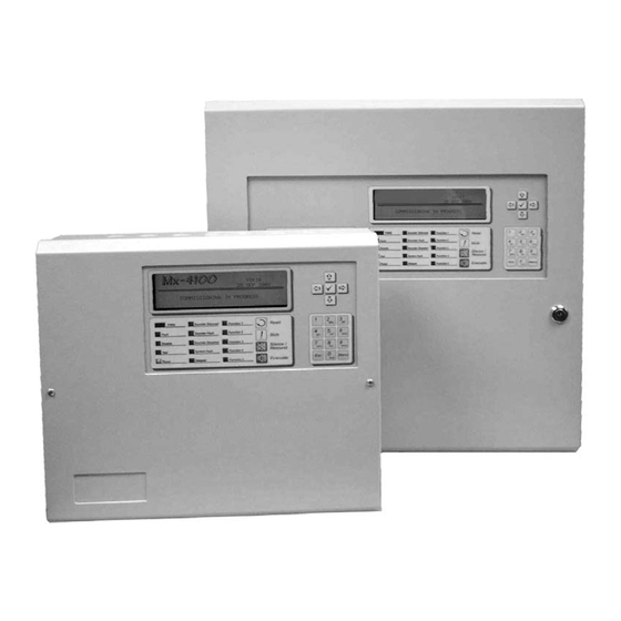
2 Controls and Indications The Mx-4100, Mx-4200, Mx-4400 and Mx-4800 are provided with indications and control functions as shown in the diagram below and described in the following text. The Mx-4800 has two such display elements, one for loops 1-4 and the other for loops 5-8. Normal operator level indications, controls and user programming can all be achieved using either display. -
Page 6: Led Status Indicators
LED Status Indicators The LED Status Indications show the basic operational state of the panel and whether the panel is in a fire alarm, fault, disabled or test condition. Function Colour Description FIRE Indicates that the system has detected a fire alarm condition Fault Yellow Indicates that the system has detected a fault condition... -
Page 7: Navigation Buttons
Navigation Buttons Press to scroll through Menu Options. Press to display more information. Press to scroll through menu Options. Press to scroll through lists of zones or devices. Press to confirm entry of numeric or letter information entry. Press to confirm selection of a menu option. Press to change some of the configuration options. -
Page 8: Changing From Access Level 1 To 2
Changing from Access Level 1 to 2 If the panel has an access key switch fitted, use the key in preference to the menu options shown below. Press the ‘MENU’ button. The level 1 menu will be displayed as shown below: [ CONTROLS DISABLED ] ENABLE CONTROLS VIEW... -
Page 9: Fire Alarm Condition
Fire Alarm Condition When the system registers a fire alarm condition the Red Fire Indicator illuminates, the internal buzzer sounds (continuously) and the display shows the zone in which the fire originated. The sounders, relays and other outputs will be turned on depending on the programming in the panel. An example of the display is shown below: - FIRE STARTED IN ZONE 0001... -
Page 10: Investigation Delays
FIRES IN ZONE 001 ] More> LP ADRS DEVICE LOCATION < List of devices within the Zone 1 001.0 KITCHEN < that are in Alarm 2 Zones in Fire][Last Fire in Z0005] < No. of Zones in Fire & Last Zone <... -
Page 11: Fault Condition
Fault Condition When the system registers a fault condition the Yellow Fault Indicator is illuminated, the internal buzzer sounds intermittently and the display shows the cause of the fault in more detail. An example of the display is shown below: ZONE 0001 DEVICE MISSING BASEMENT WEST... -
Page 12: Disablement Condition
Disablement Condition If any zones, input devices or output devices have been disabled, the DISABLE Indicator is illuminated. In addition, the SOUNDER DISABLE Indicator is illuminated if one or more sounder circuits or devices have been disabled. The display indicates the presence of zone disablement conditions in the lower half of the display as follows: LEVEL 2 Mx-4100... -
Page 13: Disabled Outputs
3.6.2 Disabled Outputs The display presents a list of all of the zones in a disabled condition with the first disablement highlighted. For example: 2 Zones with Outputs Disabled] More> Zone Mode Location 0001 DISABLED BASEMENT WEST < Zones with location text where 0100 DISABLED RECEPTION <... -
Page 14: Menu Functions
Menu Functions The following Menu Functions are available at Level 2. The display shows the primary Level 2 Menu as follows: [Level 2 Menu] VIEW DISABLE ENABLE TEST PRINT COMMISSION The following table gives a list of the Level 2 Menu Functions, the sub-functions available within each main function and a brief description for each function. -
Page 15: Using The Buttons To Navigate Menus
3.8.1 Using the Buttons to Navigate Menus Press the ‘Menu’ button to bring up the display menu. 3.8.1.1 Selecting Menu Options The Level 2 Menu is shown below: [Level 2 Menu] VIEW DISABLE ENABLE TEST PRINT COMMISSION Press the buttons to highlight the required menu option and then press the button to select it. -
Page 16: Viewing
Viewing [View Menu] FIRES FAULTS ALARMS DISABLED INPUTS OUTPUTS PANEL NETWORK LOGIC Note that Fires, Faults, Alarms and Disablements are all normally shown without having to select the view menu. If, however, you wish to manually View any of these, they can be selected from this menu as required. -
Page 17: View - Outputs
[ Inputs] More> Zone Mode Location 0001 Enabled BASEMENT WEST 0002 ALL DISABLED BASEMENT EAST 0008 Enabled GROUND FLOOR 0009 Enabled MAIN RECEPTION AREA Press the buttons to highlight the required zone and then press the button to view the full location text Press the button again to view the inputs within the zone and their status. -
Page 18: View - Panel
3.9.7 View - Panel The View Panel Option provides a diagnostic readout of the operational condition and readings for the internal panel electronic circuits. When the option is selected, the display shows a list of the circuits. For example: [Panel Circuits] ITEM DESCRIPTION VALUE STATE... -
Page 19: View - Log
3.9.8 View - Log After selecting to view the log, the display presents a pop-up window to allow selection between a view of all of the event history or a view of only the fire alarms that have occurred. Press the buttons to highlight the required menu option and then press the button to select it. -
Page 20: Disabling
3.10 Disabling On selecting the Disable Menu, the display shows four possible options. For example: [Disable] ZONE/INPUTS OUTPUTS CONTROLS DELAY-MODE Press the buttons to highlight the required menu option and then press the button to select it. 3.10.1 Disable - Zones and Inputs This option provides the means to disable a complete zone, disable all input devices except call points or disable individual input devices. -
Page 21: Disable - Outputs
Press the ‘Esc’ button to return. 3.10.2 Disable - Outputs The Disable Outputs Option enables the isolation of some or all of the outputs. If disabled, the outputs will not activate in the event of a fire alarm or other programmed event. On selection of the Disable Outputs option, a pop-up window is shown for entry of the Level 2 password (normally 10000). -
Page 22: Disable - Controls
Press the buttons to scroll through and highlight the required Output and then press the button to change the device mode. The device mode will change from Enabled to Disabled and vice-versa. Press the ‘Esc’ button to return to the Zone list and to the Main Disable Menu. 3.10.3 Disable - Controls Disabling Controls will cancel Level 2 access and return the panel to Level 1 operation. - Page 23 Select USE INVESTIGATION DELAYS to enable the operation of the Stage 1 / Stage 2 Investigation Function. If the investigation delays are in operation then the “Delayed” LED Indicator is illuminated. When the investigation delays are disabled and turned off, the “Delayed” LED Indicator is turned off. Press ‘Esc’...
-
Page 24: Enabling
3.11 Enabling On selection of the Enable Menu Option, the display shows the available Enable Functions. [Enable] ZONE/INPUTS OUTPUTS DELAY-MODE CHANGE-TIME Press the buttons to highlight the required menu option and then press the button to select it. 3.11.1 Enable - Zones and Inputs Selecting this option will show a list of zones containing disabled input devices. -
Page 25: Testing
3.12 Testing [Test Menu] ZONES DISPLAY BUZZER PRINTER Press the buttons to highlight the required menu option and then press the button to select it. 3.12.1 Test - Zones The Test Zones function provides the means to implement a one-person walk test in order to test specific call points or detectors in one or more zones. -
Page 26: Test - Display
When the activating test key is removed from the call point or the smoke clears from the detector chamber, the panel will automatically reset and clear the test condition. As an alternative to scrolling, a specific zone number can be entered by using the button to move to the zone number column, and then typing in the required number, followed by the button. -
Page 27: Printing
When the test print is completed, the display automatically reverts to the Test Options Menu. Press the ‘Esc’ button at any time to cancel the test print. 3.13 Printing [Print Menu] FEED PAPER PRINT LOG SETUP PRINTER 3.13.1 Printer Communications Settings The information is sent to the printer in a serial form. -
Page 28: Print - Feed Paper
3.13.4 Print - Feed Paper Highlight the Feed Paper Option and press the button to confirm. The display does not change but a command is sent to the printer to advance the paper. Page 28 of 28...
Need help?
Do you have a question about the Mx4100 and is the answer not in the manual?
Questions and answers