
Summary of Contents for Scully ST-15C Series
- Page 1 Single Point Overfill Prevention Control Monitor Model: ST-15C Series T e c h n i c a l M a n u a l...
- Page 2 Duocept, Dynacheck, Dynamic Self Checking, Dynamic Faylsafe, Go Anywhere, Dynamic Self-Testing, IntelliCheck, Intellitrol, Scully Intelliview, Load Anywhere, Maxsafety, R.S.V.P., Scully and V.I.P., are registered trademarks of Scully Signal Company.
-
Page 3: Table Of Contents
INDEX 1.0 GENERAL ..........................5 1.1 Description....................................5 1.1.1 Model Designations................................6 1.1.2 Explosion Proof Enclosure..............................6 1.1.3 Indicator Lights ................................... 6 1.1.4 Bypass Control Switch............................... 6 1.1.5 Indicator Light on Control Module ..........................6 1.1.6 Control Outputs .................................. 7 1.1.7 User Replaceable Fuses ..............................7 1.2 Technical Specifications .................................7 1.3 Accessory Equipment................................8 1.3.1 Sculcon Junction Box with Plug and Cable Assembly.................... - Page 4 4.0 APPENDIX ...........................16 Control Unit Enclosure Outline Drawing – DWG 31412.....................16 Outline Drawing – Sculcon Junction Box – DWG 63039.....................17 Mounting Diagram, Control Unit & Junction Box – DWG 61442 ..................18 Installation Wiring Diagram – DWG 61575..........................19 Wiring Diagram, Typical Loading Rack Control – DWG 61441..................20 Internal Wiring Diagram –...
-
Page 5: General
The ST-15C is a single point overfill prevention (or liquid level detection) Control Unit. Single point means that it can monitor only one Scully liquid level sensor and provides a relay output and a visual indication of the sensor status, dry or wet. -
Page 6: Model Designations
1.1.1 Model Designations The ST-15C Controller is available in 120VAC or 240VAC models, with or without control (bypass) switch. Model suffix (E) = Explosion-proof Enclosure, (L) = Indicator Lights, (K) = Key Lockable Bypass Switch. Model Description Single-Point Controller in Explosion-proof Enclosure with Indicator Lights, 120VAC ST-15C-120 EL ST-15C-120 ELK Single-Point Controller in Explosion-proof Enclosure with Indicator Lights and Key-lockable... -
Page 7: Control Outputs
1.1.6 Control Outputs All models of the ST-15C provide volt free, normally open contact for controlling the loading rack (gantry) valve or pump. The contact is rated at 250VAC at 5 Amps. resistive. The contact is protected by a 5A-fuse (F2) in the controller. -
Page 8: Accessory Equipment
Scully highly recommends the use of our Sculcon® Junction Box with Plug and Cable assembly. Use of Sculcon junction box simplifies system installation and provides for easy service of the plug and cable assembly for maintenance. -
Page 9: Installation
One hole in the bottom of the enclosure, labeled “Intrinsically Safe Entry” is for connection to sensors, via a Scully Sculcon Junction Box and Plug & Cable. WARNING The electrical cable entry in the bottom of the enclosure marked “INTRINSICALLY SAFE ENTRY” must only be used for wiring to the sensors (via plug and cable assembly). -
Page 10: Power Connections
There is a factory installed jumper on TB2 terminals 1 and 2. Remove the jumper if the control unit is to be used with Scully’s SP-BLHK heated product sensor. Otherwise, the jumper must be kept in place. All wiring installation should be in accordance with local wiring codes. -
Page 11: Initial System Checkout
Connect Sculcon plug to socket on the tester. Follow instructions provided with the tester. The tester is capable of checking controllers that can monitor up to 8 Scully sensors (2-wire thermistor or Optic Sensors). As ST-15C is a single point controller (monitors only one sensor) the tester only needs to test in one of the eight positions of the selector switch on the tester. -
Page 12: Maintenance
3.0 MAINTENANCE CAUTION: BEFORE PERFORMING ANY MAINTENANCE ON THE CONTROL UNIT, DISCONNECT POWER TO THE ST-15C AND WAIT FIVE MINUTES BEFORE OPENING THE ENCLOSURE. DO NOT OPEN WHEN AN EXPLOSIVE GAS IS PRESENT. 3.1 Enclosure Considering the location where the control unit will be typically mounted, it is advisable to inspect the enclosure routinely for deterioration due to environmental corrosion. -
Page 13: Indicator Lights
Reconnect the wires to TB1. Close the cover and attach the (16) cover bolts. Apply power to the Control Unit. Factory installed jumper. do not remove unless ST-15C is to be connected to a Scully Model SP-BLHK sensor. Figure 1:ST-15C Control Module Illustration Note: The ST-15C Replacement Control Module cannot be repaired in the field. -
Page 14: Control (Bypass) Switch
To protect it from loading arm damage etc., it is important to store the plug and cable out of harms way when it is not in use. A hook is provided on Sculcon Junction Box or a Scully Storage Socket may be used. -
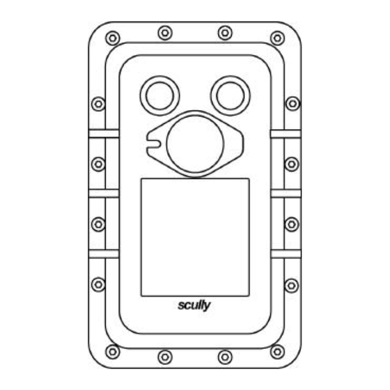
Page 16: Appendix
4.0 APPENDIX Control Unit Enclosure Outline Drawing – DWG 31412... -
Page 17: Outline Drawing - Sculcon Junction Box - Dwg 63039
Outline Drawing – Sculcon Junction Box – DWG 63039... -
Page 18: Mounting Diagram, Control Unit & Junction Box - Dwg 61442
Mounting Diagram, Control Unit & Junction Box – DWG 61442... -
Page 19: Installation Wiring Diagram - Dwg 61575
Installation Wiring Diagram – DWG 61575... -
Page 20: Wiring Diagram, Typical Loading Rack Control - Dwg 61441
Wiring Diagram, Typical Loading Rack Control – DWG 61441... - Page 21 Notes:...
-
Page 22: Internal Wiring Diagram - St-15C El - Dwg 31392
Internal Wiring Diagram – ST-15C EL – DWG 31392... -
Page 23: Internal Wiring Diagram - St-15C Elk - Dwg 31393
Internal Wiring Diagram – ST-15C ELK – DWG 31393... - Page 28 P/N 61119 REV C...
Need help?
Do you have a question about the ST-15C Series and is the answer not in the manual?
Questions and answers