
Summary of Contents for Strata Technology DCP50
- Page 1 Strata Technology Limited DCP50 High Precision Pump User Manual Part No. S000016.2 DCP50 User Manual...
- Page 2 This manual is for use with MK2 pumps only i.e. pumps with the RS485 interface. Page ii Part No. S000016.2 DCP50 User Manual...
- Page 3 – used as a stand-alone unit, or – connected to other CE-marked equipment and – used in the same state as it was delivered from Strata Technology Ltd. This is a Class A product for laboratory use only. In a domestic environment this product may cause radio interference in which case the user may be required to take adequate measures.
- Page 4 The only user serviceable parts of the DCP50 are located behind the plastic cover as described in Chapter 7. The warranty is invalidated if the end user attempts to open the DCP50 case. The warranty also applies to the external power supply, which is also invalidated if it is damaged by the end user and any attempt made to repair it.
- Page 5 © Copyright 2016 Strata Technology Limited. All rights reserved. No part of this publication may be reproduced, stored in a retrieval system or transmitted in any form or by any means, without permission in writing from Strata Technology Limited.
- Page 6 This page intentionally left blank Page vi Part No. S000016.2 DCP50 User Manual...
-
Page 7: Table Of Contents
Run Control ......................13 4.13 Pressure Safety Limit Control .................. 14 4.14 Flow Rate/Pressure Control ..................14 4.15 DCP50 Menu System ....................15 Chapter 5 Installation ......................17 Operating Environment ................... 17 Tubing ........................17 Start-up Procedure ....................19 Priming the Rinsing System ..................20 Draining the pump .................... - Page 8 Rinsing Washer Replacement .................. 35 Transfer Port Replacement..................36 Cylinder Adjusting Screw Replacement ..............37 Tubing Replacement ....................37 Updating Firmware ....................39 Returning the DCP50 for Service/Repair ..............39 7.10 Recycling ....................... 39 Chapter 8 Troubleshooting ....................41 Fault Finding ......................41 Chapter 9 Spare Parts and Accessories ................
-
Page 9: Chapter 1 Introduction
50 bar (5 Mpa, 725 psi) or constant pressure up to 50 bar is required. The DCP50 is very accurate and reproducible, especially at low flow rates over the whole pressure range. The pump’s design is such that it has excellent chemical resistance. - Page 10 Chapter 1 Introduction WARNING! If the DCP50 pump is used in a manner not specified by Strata Technology Limited, protection against personal injury inherent in the equipment’s design can be rendered ineffective. Page 2 Part No. S000016.2 DCP50 User Manual...
-
Page 11: Chapter 2 Specifications
Output voltage : 24V DC Output current : 2.71A Power consumption <24VA Environment +4°C to +40°C, 20–95% relative humidity, 84–106kPa (840– 1060mbar) atmospheric pressure. Dimensions 410 x 203 x 172 mm. Weight 10.2kg DCP50 User Manual Part No. S000016.2 Page 3... - Page 12 (emission). Operation is subject to the following two conditions: 1. This device may not cause harmful interference. 2. This device must accept any interference received, including interference that may cause undesired operation. Page 4 Part No. S000016.2 DCP50 User Manual...
-
Page 13: Chapter 3 Unpacking
(also shown below). CAUTION! The DCP50 has a weight of 10.2kg and care should be taken when lifting it. The pump should be lifted by placing the fingers under the unit at each end of the metal case and lifting. - Page 14 Chapter 3 Unpacking This page intentionally left blank Page 6 Part No. S000016.2 DCP50 User Manual...
-
Page 15: Chapter 4 Description
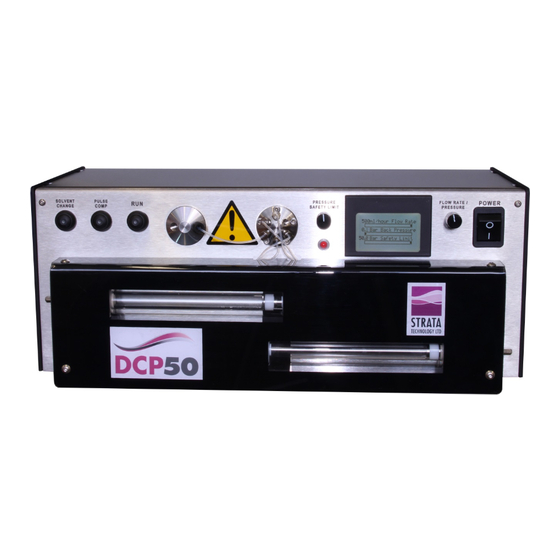
Front Cover The DCP50 is fitted with two types of covers at the front (not shown in Figure 1). Metal guards are fitted over both piston rods to cover the two openings in the front of the pump to prevent the risk of operator fingers getting trapped in the mechanism, and to reduce the risk of solvent spillage entering the pump. - Page 16 Switches power to the internal circuitry of the pump when turned on. =Off, l=On Transfer Glass Piston Tubing Cylinder adjusting Port Tube Connections screw Figure 1 - DCP50 Front Panel with protective covers removed Page 8 Part No. S000016.2 DCP50 User Manual...
-
Page 17: Pump Options
Nitronic60 for the parts that come into contact with the solvents used. For users wishing to use corrosive solvents such as brine, the DCP50 can be supplied with Hastelloy wetted parts. Apart from the piston seal retainer (see section 4.4) which is user serviceable, the Hastelloy parts have to be fitted during manufacture. -
Page 18: Rinsing System
This gives a signal output proportional to the pressure being applied. This signal is amplified and fed to the micro-controller circuit on the control board. Page 10 Part No. S000016.2 DCP50 User Manual... -
Page 19: Tubing Connectors
DC Connector The circular DC connector at the rear of the DCP50 has three pins, the smallest of which is not used. The other two pins are for the +24V DC input and the 0V connection. The pin-out of this connector is shown in Figure 4. - Page 20 2Mbit/s. The pin-out for this connector is shown in Figure 6 Figure 6 - RS485 Connector Pin-out (viewed from rear of pump) Pin No. Function RXD+ RXD- TXD+ TXD- Page 12 Part No. S000016.2 DCP50 User Manual...
-
Page 21: Solvent Change Control
4.12 Run Control The RUN button is used to start and stop the DCP50 from running. The green LED within the button indicates when this function is active i.e. when illuminated, the DCP50 is in ‘Run’ mode, and when off it is in ‘Standby’... -
Page 22: Pressure Safety Limit Control
N.B. This control automatically locks 10 seconds after last use. When the DCP50 is in either of the Constant Flow modes, the displayed back pressure may vary depending on the loading of the pump. When the DCP50 is in Constant Pressure mode, the flow rate may vary to maintain the set pressure with any changes in the loading of the pump. -
Page 23: Dcp50 Menu System
This can be updated as new releases are made available by Strata Technology Ltd. This initial menu comprises the following sub-menus, briefly described below. Each menu item is selected by use of the PRESSURE SAFETY LIMIT control, and where applicable, parameters are adjusted using the FLOW RATE/PRESSURE control. - Page 24 Chapter 4 Description This page intentionally left blank Page 16 Part No. S000016.2 DCP50 User Manual...
-
Page 25: Chapter 5 Installation
5.2.1 Internal Tubing The tubing used internally in the DCP50 is 1/16” diameter with a 69 bar pressure rating and manufactured from FEP. Over a period of time this tubing may wear out or become brittle, depending on the solvents being used, and must be replaced with the same size, type, and pressure rating of tubing. - Page 26 This will cause the metal ring to slide over the plastic ferrule to clamp the ferrule to the tube. Page 18 Part No. S000016.2 DCP50 User Manual...
-
Page 27: Start-Up Procedure
Place the outlet tubing into a suitable container to collect the water as it is pumped out. Start-up Procedure The DCP50 is tested and calibrated prior to delivery. To ensure that it is functioning correctly at switch-on, the following checks should be performed. -
Page 28: Priming The Rinsing System
Press the RUN button to stop the pump. Priming the Rinsing System If the rinsing system fitted to the DCP50 is going to be used during operation, it must first be primed with the rinsing solution (e.g. 20% ethanol). To access the rinsing tubing, remove the plastic guard at the front of the pump by unscrewing and removing the four button head screws securing it in place using the 2.5mm hex key from the tool kit. -
Page 29: Draining The Pump
LED’s will turn off. 5.5.2 Switch off the pump. The pump is now ready for use. Before using or changing solvents, refer to section 6.6. DCP50 User Manual Part No. S000016.2 Page 21... - Page 30 Chapter 5 Installation This page intentionally left blank Page 22 Part No. S000016.2 DCP50 User Manual...
-
Page 31: Chapter 6 Operation
If the DCP50 has previously been used with a different solvent to that being used this time, and there are traces of the previous solvent still in the pump, drain the pump as much as possible by using the instructions given in section 5.5, ensuring that a suitable container is used to collect the... -
Page 32: Routine Operation
During manufacture, the piston seals are ‘bedded-in’ using de-ionised water. When solvents are used with the DCP50, the seals may require re-adjusting as described in section 7.1 due to the reaction between the solvent and the seal material. It may also be necessary to ‘bed-in’ the seals again using a closed-loop system. -
Page 33: Pressure Calibration
Bulk Modulus Setting Due to the bulk compressibility of the different solvents being used in the DCP50, it is possible to set the ‘Bulk Modulus’ value for the solvent being used. This can be set between 0.50 and 2.50 in 0.01 steps and the value required for a particular solvent can be found in a book of constants. -
Page 34: Pid Controller
‘Settings’ menu. 6.5.7 Rotate the PRESSURE SAFETY LIMIT control to position the arrow (>) against ‘Back to Menu’ and then press the control to display the main menu. Page 26 Part No. S000016.2 DCP50 User Manual... -
Page 35: Solvents
6.6.4 Solvent Resistance The DCP50 pump can be used with all types of buffers, detergents and organic solvents. In addition, most inorganic and organic acids and bases e.g. diluted mineral acids, metal salt solutions, carboxy acids, anhydrides, aromatic and aliphatic hydrocarbons, alcohols, aldehydes, ketones, ethers, esters and chlorinated hydrocarbons can be used. -
Page 36: Pump Head Cleaning
Blockages can occur in the small diameter fluid pathways of the DCP50 pump if saturated solutions, such as high salinity brines, are used, due to precipitation of dissolved solids caused by temperature or pressure variations. -
Page 37: Chapter 7 Maintenance And Servicing
A list of spare parts and accessories available from Strata Technology Ltd is shown in Chapter 9. It is recommended that the DCP50 pump is wiped with a damp cloth at regular intervals. See also section 6.7 for pump head cleaning. - Page 38 7.1.12 Refit the metal guards in place, securing with the screws removed previously. When refitting the right hand guard, ensure that the two tubes from the transfer port do not become trapped by the guard, and then fit the tubes back in the clamp. Page 30 Part No. S000016.2 DCP50 User Manual...
-
Page 39: Piston Seal Replacement
The following section provides instructions on how to replace worn piston seals. Before replacing the piston seals, flush any solvent from the DCP50 using the instructions given in section 5.5, taking note of the warnings given at the beginning of this chapter. - Page 40 Withdraw the piston assembly from the glass tube. If required, clean the inside of the glass tube. Place the glass tube on a clean surface taking care that it cannot roll off of the work surface. Page 32 Part No. S000016.2 DCP50 User Manual...
- Page 41 5mm spanner, tighten the cylinder adjusting screw by 1¼ turns to ensure a good seal between the transfer port seal, rinsing washer and the glass tube. DCP50 User Manual Part No. S000016.2 Page 33...
- Page 42 7.2.28 Replace the plastic cover and secure with the four screws removed earlier. Fit the two front screws first leaving them loose, then fit and tighten the top screws before finally tightening the front screws. Page 34 Part No. S000016.2 DCP50 User Manual...
-
Page 43: Glass Tube Replacement
Some resistance will be felt when trying to rotate the washer due to the tight fit against the piston rod, but if the washer will not move, the adjusting screw is too tight. DCP50 User Manual Part No. S000016.2 Page 35... -
Page 44: Transfer Port Replacement
It is recommended that the transfer port sealing washer is replaced at the same time as the transfer port. Before replacing the transfer port, flush any solvent from the DCP50 using the instructions in section 5.5, taking note of the warnings given at the beginning of this chapter. -
Page 45: Cylinder Adjusting Screw Replacement
It is therefore recommended that only one tube is replaced at a time. If it becomes necessary to change any of the internal tubing of the DCP50, always flush any solvent out of the pump first. It is recommended that if dismantling the front of the pump to replace one section of tubing, all tubing is replaced at the same time. - Page 46 Switchover Valve port 1 to left transfer port top Place the DCP50 on a clean work surface. Remove the protective plastic cover by removing the four screws securing it in position using the 2.5mm hex key supplied in the tool kit, then remove the two metal guards over the pistons.
-
Page 47: Updating Firmware
Refit the metal guards and plastic cover in place as instructed in 7.1.12 and 7.1.13. Updating Firmware The firmware program stored in the microcontroller within the DCP50 can be updated by the end user when new versions are made available by Strata Technology Ltd. - Page 48 Chapter 7 Maintenance and Servicing This page intentionally left blank Page 40 Part No. S000016.2 DCP50 User Manual...
-
Page 49: Chapter 8 Troubleshooting
If the problem still exists, contact an electrician. LCD is blank when the DCP50 The external DC power supply Check that the power supply is switched on – no backlight. is not attached correctly... - Page 50 If this does not clear the Air bubbles seen in the debris, the pump must be cylinder that is drawing in the returned to Strata Technology solvent Limited to be serviced. The inlet tubing from the Remove the protective cover switchover valve to its and release the tubing.
- Page 51 If this does not clear the blockage, the pump must be returned to Strata Technology Limited to be serviced. Transfer Port jumping with Tighten cylinder adjusting Occasional ‘knock’ from pump...
- Page 52 Chapter 8 Troubleshooting This page intentionally left blank Page 44 Part No. S000016.2 DCP50 User Manual...
-
Page 53: Chapter 9 Spare Parts And Accessories
(S000039) at the same time as the existing seal may have been cut by the broken glass. ** If replacing individual lengths of tubing in the DCP50 between the transfer ports, switchover valve and pressure transducer, these can be cut from this part. - Page 54 Chapter 9 Spare Parts and Accessories This page intentionally left blank Page 46 Part No. S000016.2 DCP50 User Manual...
Need help?
Do you have a question about the DCP50 and is the answer not in the manual?
Questions and answers