Table of Contents
Advertisement
Advertisement
Table of Contents

Related Manuals for THORLABS MC2000

Summary of Contents for THORLABS MC2000
- Page 1 MC2000, MC2000-EC Optical Chopper Operating Manual...
-
Page 2: Table Of Contents
Cleaning ..............................19 7.2. Diagnostic Messages ..........................19 Part 8. Fuse Replacement and Line Voltage Selection ................20 8.1. Materials Needed ............................ 20 8.2. Fuse Replacement and Line Voltage Selection ..................20 18488-D02 Rev G, September 24, 2012 Page 2 www.thorlabs.com... - Page 3 12.1. Waste Treatment is Your Own Responsibility ..................28 12.2. Ecological Background .......................... 28 Part 13. Certificate of Conformity ......................29 Part 14. Thorlabs Worldwide Contacts ....................31 18488-D02 Rev G, September 24, 2012 Page 3 www.thorlabs.com...
- Page 4 Figure 3: Circuit Board Layout with 110/220 VAC Switch ..............21 Figure 4: Console Dimensional Drawing .................... 26 Figure 5: Chopper Head Dimensional Drawing .................. 27 18488-D02 Rev G, September 24, 2012 Page 4 www.thorlabs.com...
-
Page 5: Epart 1. Safety Warnings
Thorlabs provides the proper 120 VAC power input cable with each MC2000 for use in the United States and the appropriate 230 VAC input cable with each MC2000-EC for use in Europe. If using this unit anywhere else, the user will need to supply a properly grounded power cable to power the unit. If something should go wrong with the unit, do not attempt to fix. -
Page 6: Part 2. Product Overview
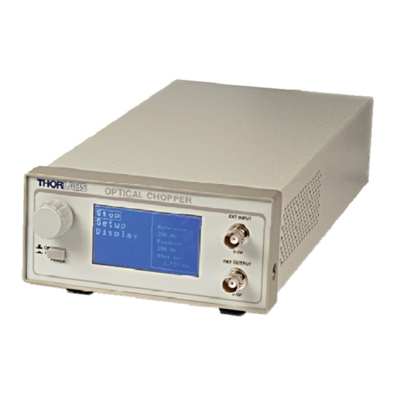
Part 2. Product Overview The MC2000 Optical Chopper is a precision instrument utilizing advanced features to meet the most demanding applications. The MC2000 uses a phased-locked loop (PLL) motor speed control design to precisely maintain the chopping speed and phase to a reference signal. An internal, crystal-stabilized, frequency synthesizer provides an accurate and stable reference frequency for long-term stable performance. -
Page 7: Front Panel Description
Cooling Fan Cord supplied for US Do not block when the operation. unit is operating. Fuse Holder USB 2.0 Port The system fuse is installed here. Figure 2: Rear Panel 18488-D02 Rev G, September 24, 2012 Page 7 www.thorlabs.com... -
Page 8: Part 3. Setup
Note: the MC2000 can be operated from 100/115 VAC or 230 VAC. A voltage selector switch is located inside of the MC2000 controller. If you are not sure what operating voltage your unit is set to, proceed immediately to Part 8. Fuse Replacement and Line Voltage Selection on page 20 for instructions on setting the operating voltage. -
Page 9: Part 4. Basic Operation
Basic Operation 4.1. Internal Reference Operating Mode The MC2000 is most often used in the internal reference mode where the chopping speed is set internally. 1. Turn the MC2000 power on. The LCD display will show the Thorlabs logo and firmware revision number before changing to the top-level menu list. -
Page 10: Reference-Out Signal
4.3. Reference-Out Signal The MC2000 supports a number of different reference out signals. For reference output selection, highlight and select the external reference out signal from the following menu list. This list is described in more detail in the following sections. -
Page 11: Part 5. Advanced Operating Instructions
The MC2000 will accept a TTL or CMOS logic level input as an external reference. The advanced PLL design used in the MC2000 even accepts reference signals that do not have a 50% duty cycle. A special feature of the external reference mode, locking to harmonics and sub-harmonics of the reference signal, is described in the following section. -
Page 12: Harmonic Reference Generation
(ACTUAL) fractional harmonic reference output signal will ever be used. 5.4. Two-Frequency Chopping A special two-frequency blade is available from Thorlabs, which has seven slots on the outer portion of the wheel and five slots on the inner part of the wheel. This unique prime number combination allows the same chopper to discriminately chop two different light paths. -
Page 13: Setting The Chopping Speed In The Two Frequency Mode
Optical Chopper System For example, the MC2000 is set to run the outer blade set at 70 Hz. The inner blade, by virtue of the ratio of inner to outer slots will be running at 50 Hz. If a light path is common to both the inner and outer blades, the signal will see a sum frequency of 120 Hz and a difference frequency of 20 Hz. -
Page 14: Selecting The Reference Out Signal
Slave: • Blade – (MC1F2) • Ref. In – (EXTERNAL) • Ref. Out – (INNER) • Freq. – Set to the desired frequency. • Phase – Set to the desired phase. 18488-D02 Rev G, September 24, 2012 Page 14 www.thorlabs.com... -
Page 15: Part 6. Remote Communications
CD and run CD-Starter.exe. Follow the onscreen prompts to install the driver. After the driver is installed, attach the MC2000 to the PC and power it on. Your PC will then detect the new hardware and will prompt you when the installation is complete. -
Page 16: Commands
The prompt symbol “>” will appear on power up and after a command is accepted by the system indicating it is ready to receive another command line. 6.3. Commands The following list shows all of the available commands and queries, and summarizes their functions: 18488-D02 Rev G, September 24, 2012 Page 16 www.thorlabs.com... - Page 17 If the keyword, format, or argument is incorrect or out of range, the unit will return an error string. The function is determined by the value set with the mode command in the above table. 18488-D02 Rev G, September 24, 2012 Page 17 www.thorlabs.com...
-
Page 18: Blade Indexes
“blade= n ”, respectively. These commands do not denote blade type using product names. Rather, they index blade type using the numbers from 0 to 7. The following table provides the mapping: Blade Index MC1F2 MC1F6 MC1F10 MC1F15 MC1F30 MC1F60 MC1F100 MC1F57 18488-D02 Rev G, September 24, 2012 Page 18 www.thorlabs.com... -
Page 19: Part 7. Maintenance And Troubleshooting
Maintenance and Troubleshooting 7.1. Cleaning The MC2000 should only be cleaned with a soft cloth and mild soap detergent or isopropyl alcohol. Do not use a solvent-based cleaner. The optical chopper wheel may build up a layer of dust over time on the leading edges of the wheel. To clean the wheel, remove it from the optical head and wipe it clean with a cloth dampened in isopropyl alcohol. -
Page 20: Part 8. Fuse Replacement And Line Voltage Selection
• 250 mA Type IEC60127-2/III, Type ‘T’ Slo-blo Fuse – The 250 mA fuse is installed from the factory and must be installed when operating the unit at 100/115 VAC. • 125 mA Type IEC60127-2/III, Type ‘T’ Slo-blo Fuse – Thorlabs supplies a 125 mA fuse to be installed when operating at 230 VAC. -
Page 21: Figure 3: Circuit Board Layout With 110/220 Vac Switch
Optical Chopper System Line Voltage Selection Switch Set the switch to the appropriate voltage. Figure 3: Circuit Board Layout with 110/220 VAC Switch 18488-D02 Rev G, September 24, 2012 Page 21 www.thorlabs.com... -
Page 22: Part 9. Visual Menu Structure
Sets the phase Sets the D harmonic Exit Exit Exit Display Intensity OFF ON Sets the LCD display Turns the display on Exit brightness and off Store Store Recall Erase Exit 18488-D02 Rev G, September 24, 2012 Page 22 www.thorlabs.com... -
Page 23: Part 10. Specifications
0 – 5 V Typ. Ref Out Impedance 200Ω Min Load Impedance 500Ω Ref Out Signals Inner/Outer Slot Chopping Blade, Synthesizer, Sum and Diff Frequencies Ref Out Selection Selectable Menu or USB command ‘O ’ 18488-D02 Rev G, September 24, 2012 Page 23 www.thorlabs.com... - Page 24 Chopping Blade Diameter Ø4.0" (Ø101.6 mm) Chopping Blade Thickness 0.010" (0.254 mm) Mounting Base 1/4"-20 (or M8) Clearance Slots Spaced 3.0" (Compatible with Thorlabs Breadboards) Mounting Hole 1/4"-20 with 1/4" Max Screw Depth Blade Specifications Chopping Blade Slots MC1F2 MC1F10 (Default Blade)
- Page 25 Fuse Size 5 x 20 mm 1) The MC2000 is shipped with a 120 VAC US style power cord while the MC2000-EC is shipped with a 230 VAC power cord. 2) The reference output and external input is short circuit protected by limiting the current to 25mA.
-
Page 26: Part 11. Drawings
Optical Chopper System Part 11. Drawings 11.4" (290 mm) 5.8" (146 mm) 2.6" (66 mm) Figure 4: Console Dimensional Drawing 18488-D02 Rev G, September 24, 2012 Page 26 www.thorlabs.com... -
Page 27: Figure 5: Chopper Head Dimensional Drawing
(R48 mm) R1.5" (R38 mm) 2.9" (75 mm) Ø4.0" (Ø102 mm) 3.6" (90 mm) 2.9" 0.4" (74 mm) (10 mm) 3.8" 2.2" (95 mm) (56 mm) Figure 5: Chopper Head Dimensional Drawing 18488-D02 Rev G, September 24, 2012 Page 27 www.thorlabs.com... -
Page 28: Part 12. Regulatory
12.1. Waste Treatment is Your Own Responsibility If you do not return an “end of life” unit to Thorlabs, you must hand it to a company specialized in waste recovery. Do not dispose of the unit in a litter bin or at a public waste disposal site. -
Page 29: Part 13. Certificate Of Conformity
Optical Chopper System Part 13. Certificate of Conformity 18488-D02 Rev G, September 24, 2012 Page 29 www.thorlabs.com... - Page 30 Optical Chopper System 18488-D02 Rev G, September 24, 2012 Page 30 www.thorlabs.com...
-
Page 31: Part 14. Thorlabs Worldwide Contacts
Optical Chopper System Part 14. Thorlabs Worldwide Contacts USA, Canada, and South America UK and Ireland Thorlabs, Inc. Thorlabs Ltd. 56 Sparta Avenue 1 Saint Thomas Place, Ely Newton, NJ 07860 Cambridgeshire CB7 4EX Great Britain Tel: 973-300-3000 Tel: +44 (0)1353-654440... - Page 33 www.thorlabs.com...
Need help?
Do you have a question about the MC2000 and is the answer not in the manual?
Questions and answers