
Related Manuals for Favor.it RS10

Summary of Contents for Favor.it RS10
- Page 1 RS10/18/22 Favor.it INSTALLATION AND MAINTENANCE MANUAL INDUSTRIAL WASHER- PUBLICATION DATE: 2 Oct 2006 EXTRACTORS 523323...
-
Page 2: Table Of Contents
1. CONTENTS Publication date 2 Oct 2006 Page: 1. CONTENTS........................1 2. WARNINGS AND SYMBOLS ..................2 2.1. PERSONAL SAFETY RULES......................2 2.2. SYMBOLS ON THE MACHINE......................2 2.3. IMPORTANT INFORMATION BEFORE INSTALLATION ..............3 3. TECHNICAL INFORMATION..................4 3.1. TECHNICAL SPECIFICATIONS 10/18/22 kg - 25/40/50 lbs CAPACITY..........4 3.2. -
Page 3: Warnings And Symbols
2. WARNINGS AND SYMBOLS TO MINIMIZE THE RISK OF FIRE, INJURY BY ELECTRIC SHOCK OR SERIOUS INJURIES OF PERSONS OR PROPERTY DAMAGE, PLEASE READ AND FOLLOW THE FOLLOWING INSTRUCTIONS: 2.1. PERSONAL SAFETY RULES GENERALLY • This English version is the original version. •... -
Page 4: Important Information Before Installation
2.3. IMPORTANT INFORMATION BEFORE INSTALLATION FOR TRANSPORTATION AND STORAGE IN CASE OF TRANSPORTATION AND STORAGE, WATCH COMPONENTS PROTRUDING FROM THE CONTOUR LINE OF MACHINE (DOOR LOCKS ETC.), TO AVOID INJURIES. • Never push, pull or exert pressure on components protruding from the machine contour line (controls, door locks etc.). -
Page 5: Technical Information
3. TECHNICAL INFORMATION 3.1. TECHNICAL SPECIFICATIONS 10/18/22 kg - 25/40/50 lbs CAPACITY CAPACITY: 10 kg / 25 lb 18 kg / 40 lb 22 kg / 50 lb DIMENSIONS PACKING: carton box carton box carton box width 700 mm / 27.6" 935 mm / 36.8"... - Page 6 CAPACITY: 10 kg / 25 lb 18 kg / 40 lb 22 kg / 50 lb CONSUMPTION Average water 90 dm / 24 gal 160 dm / 43 gal 191 dm / 50,5 gal constumption: WORKING CONDITIONS ambient temperature: from +5°C to +40°C average ambient temperature in 24 hrs: to +35°C...
-
Page 7: Dimensions And Componets Of The Machine
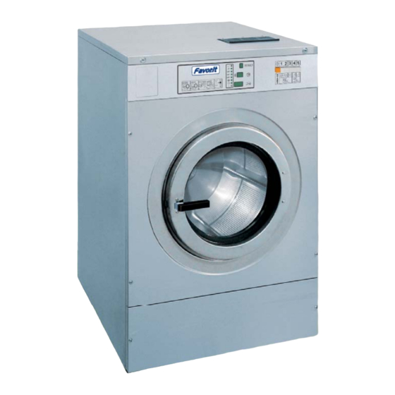
3.2. DIMENSIONS AND COMPONETS OF THE MACHINE 1. Control panel 2. Door handle 3. Service panel 4. Air vent 5. Liquid soap hose connections 6. Name plate 7. Drain connection 8. Earthing connection 9. Hot water connection 10. Cold soft water connection 11. - Page 8 10 kg 18 kg 22 kg Machine capacity: 25 lbs 40 lbs 50 lbs 660 mm 855 mm 855 mm 26" 33.7 " 33.7 " 1140 mm 1315 mm 1315 mm 44.9 " 51.8 " 51.8 " 460 mm 528 mm 528 mm 18.1 "...
-
Page 9: Installation Of The Machine
4. INSTALLATION OF THE MACHINE 4.1. HANDLING, TRANSPORT, STORAGE AND UNPACKING Only a qualified person can handle or operate the machine. STORAGE The machine is delivered to the customer in a cardboard packing and the machine is additionally protected by polyethylene foil. Do not store or install the machine where it can be exposed to environmental conditions (rain, wind) or extreme humidity. - Page 10 Fig. 4.3.A Fig. 4.3.B Fig. 4.3.C. Position of foundation bolts for machines 6 kg / 15 lbs to 22 kg / 50 lbs 1. Foundation bolt 6. Existing floor 2. Nut 7. Shim for machine type 16 kg / 35 lbs 3.
- Page 11 10 kg 18 kg 22 kg Kapacita stroje 25 lb 40 lb 50 lb 530 mm 700 mm 700 mm 20.9 " 27.6 " 27.6 " 65 mm 77,5 mm 77,5 mm 2.6 " 3.1 " 3.1 " 100 mm 100 mm 100 mm 4"...
-
Page 12: Connections
4.4. CONNECTIONS ELECTRICAL CONNECTION GENERAL WARNING ! THE MACHINE MUST BE CONNECTED TO THE POWER, GROUND, WATER, VENTILATION AND STEAM SUPPLY ACCORDING TO THE INSTALLATION MANUAL, IN COMPLIANCE WITH THE VALID LOCAL STANDARDS DONE BY QUALIFIED TECHNICIANS WITH PROPER AUTHORIZATION. THE VALID STANDARDS FOR CONNECTING TO THE LOCAL POWER NETWORK (TT / TN / IT, ...) MUST BE FOLLOWED. -
Page 13: Install Supply Cable To The Machine
Supply cable of the machine must have copper wires. The cross section of the supply wires depends on the supply voltage and on the total electrical power input of the machine (see table 3.1). The supply cable safety device against a short-circuit fault and overloading must be performed by automatic breakers or fuses in the laundry switchboard. -
Page 14: Water Supply
1. Main switch 2. Connection clamp 3. Bush Fig. 4.4.C. Connection of power supply cable to the machine DURING EXTRACTION THE DRUM SHOULD ROTATE IN CLOCKWISE DIRECTION (WHEN YOU ARE IN FRONT OF THE DOOR OF THE MACHINE). IF THIS IS NOT THE CASE THEN YOU MUST INTERCHANGE U (L1) AND V (L2) WIRES ON SUPPLY CABLE TO MAIN SWITCH –... -
Page 15: Putting Into Service
WATER DRAIN CONNECTION The machine is equipped with 76 mm / 3“ drain valve without pump, which should be connected to the main drain pipe or to the gutter. The main drain pipe must have the capacity to be able to handle the total output of all connected machines. -
Page 16: Maintenance
5. MAINTENANCE WARNING ! ALWAYS FOLLOW SAFETY INSTRUCTIONS! DO NOT BYPASS ANY SAFETY DEVICES OR THEIR PARTS. ANY INTERFERENCE TO THE MACHINE FUNCTIONS AND CONSTRUCTION ARE PROHIBITED! USE THE PROPER CHEMICAL AGENTS WHICH AVOID CALCIUM SEDIMENTS ON HEATING ELEMENTS AND OTHER MACHINE PARTS. DISCUSS THIS ISSUE WITH YOUR SUPPLIER OF WASHING PRODUCTS. THE MANUFACTURER OF THE MACHINE IS NOT RESPONSIBLE FOR THE DAMAGE OF HEATING ELEMENTS AND OTHER MACHINE PARTS DUE TO CALCIUM SEDIMENTS. -
Page 17: Water Filter
5.5. WATER FILTER CLEANING OF FILTER Close the main water supply. IF MACHINE HOT WATER SUPPLY LINE IS TOO HOT, DO NOT CONTINUE ! DANGER OF INJURY! If machine hot water supply line is cold and closed you can clean the filter. Water filter is accessible after disconnecting the supply hose. Clean up the filter and put it back. - Page 18 • If it is not possible to install the belt on the tension pulley, we can move the motor (16). Loosen the bolt M8 (11) which ensures the correct position of the motor. Move the motor to enable the belt installation and fasten it. Tighten the securing bolt (11) carefully so that it would not deform the plastic washers (14,15).
-
Page 19: Fuses
• Turning the drum pulley (1) slowly and by the belt (2) offset from its working position at the same time, you will reach tension reduction and you can remove the pulley. • Put the new belt of the same type on the motor pulley (4) first and then partly on the drum pulley (1), so that the tension spring (6) is hooked. -
Page 20: Trouble Shooting Aids
6. TROUBLE SHOOTING AIDS 6.1. EMERGENCY DOOR OPENING Whenever the door fails to open, e.g. in case of a current failure or in emergency situation, we recommend you to proceed as follows: • Before the door is open, check the washing water temperature and machine parts temperature. IF THESE PARTS ARE TOO HOT, DO NOT OPEN ! DANGER OF INJURY ! •... -
Page 21: List Of Recommended Spare Parts
7. LIST OF RECOMMENDED SPARE PARTS You can find more exact information in the spare-part manual for individual machines. PRI 346 000 003 Bimetal 230V PRI 610 012 077 Coil PRI 610 008 077 Coil PRI 610 011 077 Micro-switch PRI 610 032 077 Micro-switch PRI 340 055 051... -
Page 22: Putting The Machine Out Of Service
8. PUTTING THE MACHINE OUT OF SERVICE 8.1. DISCONNECTING THE MACHINE 1. Disconnect the outer electric power supply from the machine. 2. Switch off the main switch located on the back of the machine. 3. Turn off the outer water or steam inlet. 4. -
Page 23: Serial Number
IMPORTANT ! MACHINE TYPE: PROGRAMMER: -ELECTRONIC TIMER MCB EC INSTALLATION DATE: INSTALLATION CARRIED OUT BY: SERIAL NUMBER: ELECTRICAL DETAILS: .....VOLT....PHASE....HZ NOTE: ANY CONTACTS WITH YOUR DEALER REGARDING MACHINE SAFETY, OR SPARE PARTS, MUST INCLUDE THE ABOVE IDENTIFICATION. MAKE CERTAIN TO KEEP THIS MANUAL IN A SECURE PLACE FOR FUTURE REFERENCE.
Need help?
Do you have a question about the RS10 and is the answer not in the manual?
Questions and answers