
Related Manuals for Krautkramer DM4E


Summary of Contents for Krautkramer DM4E
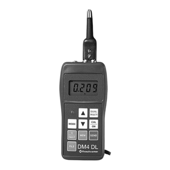
- Page 1 ® Advanced Test Equipment Rentals www.atecorp.com 800-404-ATEC (2832) DM4E DM4 DL Operating Manual...
-
Page 2: Operating Manual
Operating Manual Ultrasonic Thickness Gauge DM4E, DM4 Models DM4 DL with On-board data Logger Manual Part No. 021-002-073 REV. S Copyright 2002 Agfa NDT Inc. - Page 3 THIS PAGE INTENTIONALLY BLANK...
-
Page 4: Important Notice
Areas covered by the sound instrument is calibrated is the sound beam. velocity of the material being tested. Operators must be familiar with the use Actual sound velocities in materials of ultrasonic couplants. Testing skills Page 1 DM4E, DM4, DM4 DL Operating Manual... - Page 5 This is particularly important when the test piece is being ultrasonically measured for the first time or in any case where the history of thickness of the test specimen is unknown. Page 2 DM4E, DM4, DM4 DL Operating Manual...
-
Page 6: Table Of Contents
3.5 Selecting Locations ........18 1.1 How To Use This Manual ......... 5 3.6 Reviewing Stored Thickness Readings ..18 1.2 DM4E, DM4, DM4DL Features ....... 5 3.7 Clearing and Replacing Readings ....19 1.3 How Instrument Measures Thickness ....5 3.8 Clearing Selected Files ......... -
Page 7: Warranty/Service
However, should service become necessary, Agfa NDT Inc. Krautkramer DM4E, DM4, and DM4 DL test instruments has established a number of Factory Trained Service Centers. are conditionally guaranteed to be free from defects in... -
Page 8: Introduction
Automatic probe zero for fast calibration • Automatically recognizes DIALOG Intelligent Transducers. This manual describes the features and operation of the DM4E, DM4, and DM4 DL (with on-board data logger) Ultrasonic Thick- • Automatic V-path error correction compensates for non- ness Gauges. - Page 9 The result is the thickness of the material. The figure at right illustrates the pulse-echo principle of ultrasonic thickness measurement. Dual Element Thickness Measurement Page 6 DM4E, DM4, DM4 DL Operating Manual...
-
Page 10: Operation
Note: To charge the unit of measure and display resolution refer to Section 2.14. 2.2 Displays Symbols Thickness measurement and standard 1-point calibration mode. Dual Multi “Through Coating (paint)” SPEC measurement mode. Page 7 DM4E, DM4, DM4 DL Operating Manual... -
Page 11: Keyboard Controls
NOTE: The scrolling keys are also used to change the resolution and unit of measure by pressing both keys simultaneously in THK mode (CAL indicator must be off) Page 8 DM4E, DM4, DM4 DL Operating Manual... -
Page 12: Getting Started
(Section 2.5) or 2-point calibration (Section 2.6). will resume at the same speed. Figure 2-4 shows how the display should appear with a 0.200 inch calibration standard. NOTE: DM4E, DM4 and DM4 DL feature automatic probe zero for standard probes and automatic probe recognition for Press again to end the calibration procedure. -
Page 13: Calibration To A Known Thickness,2-Point
) lights and the reading is stable. You may keep the probe coupled or uncouple and wipe the excess couplant from the probe face. to adjust the displayed value to match the thickness of the thin calibration standard. Page 10 DM4E, DM4, DM4 DL Operating Manual... -
Page 14: Calibration To A Known Velocity
NOTE: This information is provided for the convenience of the user and Agfa NDT Inc. assumes no responsibility for inaccura- cies. Actual velocities depend on exact composition, temperature, and processing of each material. Page 11 DM4E, DM4, DM4 DL Operating Manual DM4E, DM4, DM4 DL Operating Manual... -
Page 15: Normal Measurement - Thk Mode
Automatic gain High gain Figure 2-13 Medium gain Low gain 2.9 Minimum Capture Measurement to select a new setting. To enable the minimum capture mode, press until MIN illuminates. Page 12 DM4E, DM4, DM4 DL Operating Manual... -
Page 16: Using Lo/Hi Thickness Limits (Dm4, Dm4 Dl)
Use to set the limit (0.020 to 20.00"; Figure 2-18 0.5 to 500 mm). Press again to return to display. Press to return to THK mode. Page 13 DM4E, DM4, DM4 DL Operating Manual... -
Page 17: Band Pass Filter Control (Dm4, Dm4 Dl)
3 seconds.. When the instrument shuts off, the resolution setting is saved and restored when the unit is turned on. Page 14 DM4E, DM4, DM4 DL Operating Manual... -
Page 18: Recording Measurements (Dm4 Dl)
. The location where the reading has been stored is displayed briefly (Figure 2-20). After a displayed reading has been sent, the SEND key is disabled until a new reading is taken. Zero values cannot be recorded. Figure 2-21 Page 15 DM4E, DM4, DM4 DL Operating Manual... -
Page 19: Da3 Operating Mode
This means that the acoustic zero point is dynamically adjusted during the measurement process, compensating for wear and “growth” during measurements. This mode may offer advantages for certain applications such as high temperature measurements. Page 16 DM4E, DM4, DM4 DL Operating Manual... -
Page 20: Data Logger Operation
PC (Section 4.5). Individual readings and velocity can be configured files, 1 through 806. sent to the Krautkramer DR1 Data Recorder. Refer to Chapter 4 for information on connecting external devices. NOTE: DIALOG Intelligent Transducer I.D., LO limit, HI limit, and dIF value are saved with each file. -
Page 21: Logging Readings Into Memory
Section 3.5. File Full: displays when SEND is attempted to a file with no empty locations. No data is recorded. To select another file, refer to Section 3.3. Figure 3-5 Page 18 DM4E, DM4, DM4 DL Operating Manual... -
Page 22: Clearing And Replacing Readings
Press and hold for 3 seconds. DM4 DL briefly displays “C.nnn” (Figure 3-7). “nnn” is the cleared file number. Then “- F.nnn” is displayed (empty file, Figure 3-2 on page 31). DM4E, DM4, DM4 DL Operating Manual Page 19... -
Page 23: Serial I/O Interface
To change the baud rate setting, press until SPEC illumi- - Printer cable from Agfa NDT Inc. If necessary, follow the nates. procedure in Section 4.2 to set baud rate to match that of the printer. Page 20 DM4E, DM4, DM4 DL Operating Manual... -
Page 24: Sending Data To A Personal Computer
Section 4.4. to select another file to report. To abort the transmission, press while readings are being printed. The DM4 DL displays Abor. Figure 4-4 DM4E, DM4, DM4 DL Operating Manual Page 21... -
Page 25: Importing Data Into A Spreadsheet
Abor, and return to the cur- rently selected file number. In this case, the entire transmission must be repeated by following the procedure in Section 4.4, if printing data, or Section 4.5 Page 22 DM4E, DM4, DM4 DL Operating Manual... -
Page 26: Specifications
Via SEND key Report Languages: English, German, French, Italian, Spanish, Russian, and Japanese Memory Retention: Typically 10 years Display Type: Four digit, 0.5 inch (12.7 mm) high, Liquid Crystal Display with electroluminescent backlight DM4E, DM4, DM4 DL Operating Manual Page 23... -
Page 27: Probe Specifications
<1000°F . 12.7mm .75 to 250 mm <538°C NOTE: HT400 actual measurement range depends upon surface condition and couplant. HT400 temperature cycling required with surface temperatures above 400°F per Krautkramer instruction card. Page 24 DM4E, DM4, DM4 DL Operating Manual... -
Page 28: Dual Multi "Through Coating" Mode Probe Specifications
Probe specifications are subject to change without notice. DM4E, DM4, DM4 DL Operating Manual Page 25... -
Page 29: Application
Model condition. The problem can usually be corrected by rotating HT400. A special couplant, Krautkramer ZGM, and duty the probe so that the crosstalk barrier is at a right angle to the cycle are also required for high temperature use. The grooves, or using the Dual Multi measurement mode. -
Page 30: Application Notes
• 30 to 120 seconds for temperatures from 550°F to 1,000°F flaw detection instrument. Before taking another reading, carefully remove the remaining couplant and residue from the probe. DM4E, DM4, DM4 DL Operating Manual Page 27... -
Page 31: Worldwide Service Centers
United Kingdom Phone: (44) 0845 601 5771 Fax: (44) 0845 130 5775 E-Mail: ndtsales.gb.ng@Agfa.co.uk Agfa NDT SA 68, Chemin des Ormeaux F-69760 LIMONEST France Phone: (33) 47-217-9220 Fax: (33) 47-847-5698 E-mail: ndt@France.Agfa.co Page 28 DM4E, DM4, DM4 DL Operating Manual... -
Page 32: Appendix A: Displays, Quick Reference
Disable mode or feature; (DM4, DM4 DL) Backlight off, Statistics off, Section 2.11 Header off High limit alarm mode 2-point calibration - (DM4, DM4 DL) Couple to thin standard Section 2.11 Section 2.6 DM4E, DM4, DM4 DL Operating Manual Page 29... - Page 33 Sections 3.4.1, 3.6 (DM4 DL) All files selected File no. 1 empty Ready to transmit or clear File no. 1 empty Sections 3.3, 3.9, 4.4, 4.5 Section 3.3 (DM4 DL (DM4 DL) Page 30 DM4E, DM4, DM4 DL Operating Manual...
- Page 34 Spanish report language printer setting selected Section 4.3 (DM4 DL) Section 4.4 (DM4 DL) Sending ALL files Russian report language Transmission in process selected Section 4.3 (DM4 DL) Section 4.4, 4.5 (DM4 DL DM4E, DM4, DM4 DL Operating Manual Page 31...
- Page 35 Transmission in process Section 4.4, 4.5 (DM4 DL) File SEND aborted Section 4.4, 4.5 (DM4 DL) Spreadsheet formatted report Section 4.6 (DM4 DL) Non-compatible probe for Dual Multi measurement mode Section 2.18 Page 32 DM4E, DM4, DM4 DL Operating Manual...
-
Page 36: Appendix B: Locations Per File
4928 5220 113-115 4945 5198 116-117 4914 5217 118-121 4961 5184 122-123 4920 5194 124-126 4914 5200 127-129 4902 5202 130-132 4884 5200 133-135 4860 5194 5184 ** Maximum number of Readings DM4E, DM4, DM4 DL Operating Manual Page 33... -
Page 37: Appendix C: Operational Software Reset
To verify that a successful reset has occurred, switch to VEL (velocity) mode and check the displayed velocity value. The factory default value of .2313 in/µs should be displayed. If it is not, repeat the procedure. Page 34 DM4E, DM4, DM4 DL Operating Manual... -
Page 38: Index
THK Mode ..............12 Interface, I/O ..............20 Interrupted Transmission Procedure ......22 Unit of Measure ............14 Keyboard Controls ............8 VEL Mode ..............14 Language ..............20 Warranty ................. 4 DM4E, DM4, DM4 DL Operating Manual Page 35...
Need help?
Do you have a question about the DM4E and is the answer not in the manual?
Questions and answers