Table of Contents
Advertisement
Quick Links
Advertisement
Table of Contents

Related Manuals for HS Tarm TPK


Summary of Contents for HS Tarm TPK
- Page 1 - with or without Scandpell...
-
Page 2: Table Of Contents
Contents 1. Included in the delivery ..............................3 1.1 Included in the delivery of the TPK with Scandpell ........................3 1.2 Included in the delivery of the TPK without burner ........................4 2. Product summary ................................5 2.1 TPK with Scandpell ..................................5 2.2 TPK ........................................6... -
Page 3: Included In The Delivery
1. Included in the delivery The boiler is available in 2 versions: TPK by itself for installation with another supplier’s pellet burner or the TPK together with the Scandpell wood pellet burner. 1.1 Included in the delivery of the TPK with Scandpell ... -
Page 4: Included In The Delivery Of The Tpk Without Burner
1.2 Included in the delivery of the TPK without burner Pre-fitted boiler with casing The boiler is configured for connecting a pellet burner on its left or right side, or if neither of these positions can be used, it can be connected via the cleaning access door ... -
Page 5: Product Summary
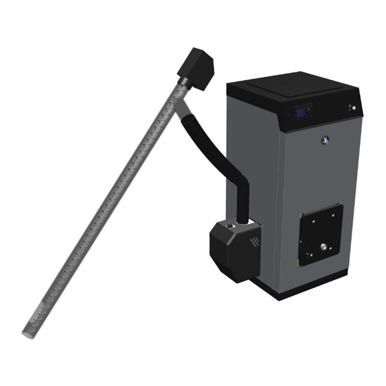
2. Product summary 2.1 TPK with Scandpell 1. Operating panel for Scandpell (this operating panel is used only for this boiler version) 2. Control unit for Scandpell 3. Overheat thermostat 4. Scandpell burner – can be connected to the left or right side. Shown here on the left side 5. -
Page 6: Tpk
2.2 TPK 9. Blank on both sides (fitted when delivered without Scandpell) 10. Pellet burner can be connected on either left or right side 11. Mechanical cleaning system for heat exchanger 12. Cleaning access door with inspection window – can be used to connect burners that cannot be connected to left or right side. -
Page 7: Scandpell Wood Pellet Burner
2.3 Scandpell wood pellet burner The TPK with Scandpell is delivered with the burner ready for use. It is simply a matter of placing the burner on the desired side of the boiler and plugging it into the control unit. -
Page 8: Installation
3.1 Installing the burner: TPK with Scandpell: The Scandpell can be installed on the right or left side of the TPK. The boiler is completely symmetrical based around the combustion chamber and the 2 coupling connector holes for connecting the Scandpell burner. -
Page 9: Installation With Storage Tank (Scandpell)
55 °C to the boiler. 3.2.1 Installation with storage tank type O and separate hot water tank 1: TPK/Scandpell 2: Loading Unit 55 °C (you could also use a thermostatic 3-way valve and pump – (use a balancing valve on the shunt loop) - Page 10 3.2.2 Installation with storage tank BS with integrated domestic hot water tank. 1: TPK/Scandpell 2: Loading Unit 55 °C (you could also use a thermostatic 3-way valve and pump – (use a balancing valve on the shunt loop) 5: Safety valve...
-
Page 11: Installation With Domestic Hot Water Tank (Scandpell)
55 °C to the boiler from the unit. 3.3.1 Installation with pump for domestic hot water priority 1: TPK/Scandpell 2: Loading Unit 55 °C (you could also use a thermostatic 3-way valve and pump – use a balancing valve on the shunt loop. -
Page 12: Installation With Thermostatically Controlled Domestic Hot Water Production
3.3.2 Installation with thermostatically controlled domestic hot water production 1: TPK/Scandpell 2: Loading unit 55 °C (you could also use a thermostatic 3-way valve and pump – use a balancing valve on the shunt loop 3: Hot water tank VBF 85, VBF 100 or VBF 150... -
Page 13: Installation In Combination With Solar Collector System (Scandpell)
Below installation examples are based on the use of solar collector systems from HS Tarm. If using other solar collector systems the examples might not be useable. Please check the function options for the solar collector systems of other manufacturers before deciding the final installation. -
Page 14: Installation With Solar Storage Tank Bs With Integrated Domestic Hot Water Tank
3.4.2 Installation with solar storage tank BS with integrated domestic hot water tank 1: TPK/Scandpell 2: Loading unit 55 °C (you could also use a thermostatic 3-way valve and pump – use a balancing valve on the shunt loop 3: Storage tank type BS (800, 1000 or 1500 liter) -
Page 15: Installation With Solar Hot Water Storage Tank
3.4.3 Installation with solar hot water storage tank 1: TPK/Scandpell 2: Loading unit 55 °C (you could also use a thermostatic 3-way valve and pump – use a balancing valve on the shunt loop) 3: Safety valve 4: Solar collector system Solar package A or B... -
Page 16: Installing The Tpk
3.5 Installing the TPK 3.5.1 Clearance requirements 0,3 meter 0,5 meter According to Danish regulations, there must be a minimum distance of 0.5 meters from anything flammable in front of the boiler (see UK building regulations). There must be a minimum distance of 0.3 meters from anything flammable to the side of the boiler opposite the burner. -
Page 17: Flue/Chimney
Necessary minimum chimney draft: 0.1 mbar 3.5.3.2 TPK with a burner from another supplier When installing a burner other than a Scandpell, the same precautions should usually be taken as when using a Scandpell. -
Page 18: Initial Operation - Tpk With Scandpell
4. Initial operation – TPK with Scandpell Once the system has been set up and connected to the mains (see the wiring diagrams under 7.2), the fuel container must then be filled with fuel. 4.1 Filling the feeder tube The time taken to fill the feeder tube with fuel is dependent on a number of factors. This is affected by both the diameter and length of the wood pellets, and the angle of the feeder tube also has a considerable influence on this. -
Page 19: Test Of Fuel Quantity
4.2 Test of fuel quantity The quantity of fuel should be tested before the burner it put into operation. The quantity of fuel for firing has a standard been set to 15 seconds. This time should give between 75 to 100 g fuels in the combustion chamber. Loosen the feed pipe from the burner and let it end in a bucket or similar. -
Page 20: Daily Use
5. Daily use 5.1 TPK with Scandpell 5.1.1 Operating the control unit Functions of the buttons: Button Function 1 Function 2 Explanation MENU Pressing this button Pressing for longer than briefly changes the 3 seconds changes the display to the user menu display to the ”Service... - Page 21 Displays: Display when neither hot water nor storage tank function is activated and the pump is activated as boiler pump. Display when neither hot water nor storage tank function is activated and the pump is activated as heating pump. Display when storage tank function is activated: Display when hot water tank function is activated: Menu functions: Pressing the MENU button provides access to the USER and SERVICE MENUS:...
-
Page 22: User Menu
User menu: User menu Text Default Min. value Max. value Explanation values Boiler parameters 1) Set point temp. 65 °C E.g. 65 °C 2) E.g. 85 °C 2) Desired boiler temperature Summer/winter Winter Winter Summer If summer is selected the heating circuit pump stops Storage tank 3) Set point temp. - Page 23 ”Service menu”: ”Service menu” Text Default Min. value Max. Explanation values value Extra sensor OFF, hot water, storage tank Selection function extra temperature sensor Extra pump function Circ. pump, boiler pump Boiler- Selection of function for pump pump Boiler parameters Min.
-
Page 24: Descriptions Of Functions
Test outputs: Test element (output) Default Press OK and change to: Boiler pump Hot water pump Feeder auger Burner auger Ignition element Cleaning Pressing OK again toggles between OFF and ON Test inputs: Test element (input) Current value (example values) Boiler sensor 50 °C Light sensor... - Page 25 5.1.2.2 Installation with storage tank If this type of installation is selected, it is the temperature in the storage tank that determines when the burner starts up, and when the burner is in standby. The storage tank functions in principle as an extension of the boiler volume. When the storage tank sensor (extra sensor has been selected to function as a storage tank sensor –...
-
Page 26: Maintenance - Tpk With And Without Scandpell
5.2 Maintenance - TPK with and without Scandpell 5.2.1 Cleaning the heat exchanger The boiler is fitted as standard with a manual mechanical system for cleaning the heat exchanger. The handle on the front of the boiler is used to move the turbulators in the heat exchanger up and down, and in this way removing ashes and soot. -
Page 27: Errors
6. Errors Alerts for stoppages resulting from faulty equipment or ignition/operating errors caused by lack of fuel are shown on the display in the direct text. At the same time errors in other parts of the burner equipment are shown on the display. The screen may appear as follows: Critical alarms are cleared by pressing STOP once the cause of the alarm has been eliminated. - Page 28 Alerts in alert window: Alert Error causes Rectification Auger circuit The main plug on the burner is not correctly placed. The plug is tight to place – press it to fit. Condensator to the auger motor is either defective or If the condensator is defective operation can there is a loose connection.
-
Page 29: Failing To Ignite
6.2 Failing to ignite If the burner fails to ignite, this can have multiple causes. Here are some of the most common combined with their symptoms: After a failed ignition there is no or nearly no fuel in the burner: o The plug to the feeder motor is loose: ... - Page 30 After a failed ignition too much fuel has built up in the burner – perhaps the complete boiler is full o The light sensor gets false light: The jacket has been removed from the burner The light sensor is not correctly placed o The minimum light level is too close to the light level at no fire: ...
-
Page 31: Product Data
7. Product data Vare nr. Tekst 016024 Brænderhoved 7.1 Spare parts Scandpell 016002 Brænderzone 016003 Ventilator 016004 Bagplade for brænder 016005 Tændelement 016006 Elforbindelse 016007 Fiberpakning 016008 Sneglemotor brænder 016009 Snegl brænder 016010 Flammesensor 016017 Sneglemotor 016016 Snegl 016015 Snegle rør 016021 Kappe for snegl 016019... -
Page 32: Tpk Spare Parts
7.2 TPK Spare parts Section 1 – cabinet: Item Part no. Description Item Part no. Description 015913 Base plate 015935 Adjustable plate 015915 Side panel 015934 Supports 015916 Back panel 015947 Internal control unit holder 015917 Front panel 015985 Blank panel... - Page 33 Section 2 – accessories GODKEND Item Part no. Description Item Part no. Description Item Part no. Description 015440 Ash door 015931 Plate - man. cleaning 015921 Cover 010084 Ash door hinge 015131 Hinge – man. cleaning 506012 Insul.stone – cover 050014 Centre bolt 015932...
-
Page 34: Electrical Connection
7.3 Electrical connection 7.3.1 Scandpell 7.3.1.1 Connections in the burner 1 2 3 4 5 6 7 8 9 10 11 12 13 14 15 Item Description Item Description Burner auger motor Burner auger motor Burner auger motor Fan (earth) Condenser Earth for burner housing Condenser... - Page 35 7.3.1.3 Connections inside the control unit A B C D N L N L N L N N L L Item Description Item Description Mains connection (1x230 VAC, with a fuse External start/stop input rated at max. 13 A) Boiler pump or circuit pump Hot water sensor / storage tank sensor *) Hot water pump Boiler sensor...
-
Page 36: Operating Safety Scandpell
The burner will then have to be re-started. 7.4.3 Protection against the boiler overheating When delivered with a Scandpell unit, the TPK is equipped with an overheat thermostat that is connected on delivery to the power supply. 7.3.4 Function check of the safety system... -
Page 37: Dimensions, Weight And Output
7.5 Dimensions, weight and output 7.5.1 Scandpell Output 6.5 – 24 Efficiency (together with TPK) 90 – 91 Weight Feeder auger length Pellet size 6 – 8 Mains supply 1 x 230 Min. combustion chamber depth Minimum chimney draw mbar... -
Page 38: Eec Declaration Of Conformity
8. EEC declaration of conformity... -
Page 39: Test Certificate
9. Test certificate... - Page 40 Rev. 11/100913...
Need help?
Do you have a question about the TPK and is the answer not in the manual?
Questions and answers