Table of Contents
Advertisement
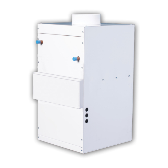
Small Duct High Velocity Heating, Cooling and Home Comfort Systems
Features:
• Quiet Operation
• Constant Air Circulation
• Multi-Positional Fan Coil
• Easy Installation & Maintenance
• Space Saving Small Diameter Ducts
• Zoning Capable right out of the Box!
• Many Attractive Vent Plate Options
• Superior Heating, Cooling and IAQ
• Eliminate Hot and Cold Spots
HE-Z Series
Installation Manual
Includes:
Hi-Velocity Fan Coils
Heating Coils/Modules
Cooling Coils/Modules
Wiring and WEG Settings
Add-ons and Options
Product Specifications
Module-HE-Z-Hi-Velocity-HE-Z-Series-Installation-Manual-051717
Manufactured By
Advertisement
Table of Contents

Related Manuals for Hi-Velocity HE-Z Series


Summary of Contents for Hi-Velocity HE-Z Series
- Page 1 Small Duct High Velocity Heating, Cooling and Home Comfort Systems HE-Z Series Installation Manual Includes: Hi-Velocity Fan Coils Heating Coils/Modules Features: Cooling Coils/Modules • Quiet Operation Wiring and WEG Settings • Constant Air Circulation Add-ons and Options Product Specifications • Multi-Positional Fan Coil •...
-
Page 2: Table Of Contents
Module ESH Placement, Configuration, Wiring Diagram Add-Ons and Third Party Options - Pgs. 40-41 Module TPA Hi-Velocity Air Purification System, Turbo Meter, Fresh Air Make-Up, Fire Stopping, Humidifiers Diagnostics and Troubleshooting - Pgs. 42-49 Module DIA Troubleshooting: WEG, Motor Running Too Fast, Motor Running Too Slow, Motor Not Running, 24V Htg, 24V Clg., Outdoor Unit, Short Cycling... - Page 3 Module - Pg. 36 Coil - Pg. 38 Fan Coil Circuit Other Options Board - Pg. 21 *Example Configuration WEG Variable Hi-Velocity Air Only Frequency Purification System Drive - Pg. 22 Module INT Introduction to Hi-Velocity (1/3) © 1995-2017 Energy Saving Products Ltd.
- Page 4 For residential applications where every cubic foot of area is critical, the Hi-Velocity System is the solution to your Primary Applications: heating and cooling needs. Being able to run duct work into...
-
Page 5: Module Int
The descriptions and specifications contained in this document were in effect at printing. Some illustrations may not be applicable to your unit. Module INT Introduction to Hi-Velocity (3/3) © 1995-2017 Energy Saving Products Ltd. -
Page 6: Module Otl
Outlets do not have to be located on an outside wall. Due to the Proper location is critical to the operation of the Hi-Velocity venturi action of the Hi-Velocity System, the air in the entire room System for optimum home comfort. The outlets should be is gently circulated at all times. - Page 7 Avoid placing vents directly 4c - Floor installed Rough-In Boot below sinks or other locations people will be for extended 4d - Wall installed Rough-In Boot periods of time. Module OTL Hi-Velocity Outlet Installation (2/2) © 1995-2017 Energy Saving Products Ltd.
-
Page 8: Module Fcp
The Hi-Velocity System fan coil is manufactured with a direct drive permanently lubricated VFD Motor that is mounted within the blower. All Hi-Velocity fan coils are single side access. The blower assembly can easily be slid out by removing the three mounted bolts that attach it to the center plate. - Page 9 Attach the metal flanges to the four facing corners of the fan coil and cooling coil assembly. After attaching the metal flanges, follow the same steps for hanging fan coil unit only. FCP-07b Module FCP Hi-Velocity Fan Coil Placement (2/2) © 1995-2017 Energy Saving Products Ltd.
-
Page 10: Installing Plenum And Branch Duct - Pgs
Location There are five types of connections that are possible with the When locating the plenum duct, one of the main factors to Hi-Velocity System. consider is the integration of the duct work into the structure. Fig. DUC-03 - Connectors The main supply duct can be located along the main beam(s) in the basement (Fig. -
Page 11: Module Duc
Module DUC Installing Plenum and Branch Duct (2/9) www.hi-velocity.com Bullhead Tees Fig. DUC-05 - Sigma Velocity Profile Bullhead tees are to be maintained as close to a 50/50 split as possible, with a maximum 60/40 split (DUC-Fig. 07). For the best... - Page 12 Module DUC Installing Plenum and Branch Duct (3/9) www.hi-velocity.com Connecting Plenum to Fan Coil To install the insulation sleeve over the main plenum, either tape the end of the duct or use an end cap. This will allow After the main plenum duct and the fan coil unit are in place, the sleeve to slide on easier, and prevent the insulation from they can be fitted together.
- Page 13 HE Duct is designed as a direct alternative for two 2” (51mm) flex (7mm) self tapping screws (Fig. DUC-13b). duct of the same length used in Hi-Velocity Systems. No changes Fig. DUC-13a - Branch Take-Off are required to fancoil selection and main plenum duct sizing.
- Page 14 Module DUC Installing Plenum and Branch Duct (5/9) www.hi-velocity.com Flexible Duct Placement When larger holes (4”/102mm) can be drilled, then the insulated flex duct may be pulled through whole. If code or the After all of the Branch Take-Offs have been installed, the designer only allow for a 2 3/8”...
- Page 15 Module DUC Installing Plenum and Branch Duct (6/9) www.hi-velocity.com Connecting to the Main Plenum Fig. DUC-20 - Fasten with tie straps The Flexible Duct coupling is connected to the branch Take- Off, then mechanically fastened with at least one ¼” (6.7mm) self tapping screw.
- Page 16 Module DUC Installing Plenum and Branch Duct (7/9) www.hi-velocity.com Installing 2” Vents in Retrofits Fig. DUC-27 - Secure flex to Rough-In Boot For ease of installation, it is recommended to use the 2” (51mm) flexible duct and vents for retrofit applications. With the proper preparations, installing vents into finished walls and ceilings is quick and simple.
- Page 17 Fig. DUC-35 - 6”/7” Apart on Center (152mm/178mm) Vane vent grill is the only type of linear grill that can be used 6”/7” (152mm/177mm) with the Hi-Velocity System (Fig. DUC-34). Linear grills must be 6”/7” purchased from a third party vendor. (152mm/177mm) Fig.
- Page 18 If the static pressure is high, drilling more holes into the main plenum will lower the static pressure and the noise level of the system. The standard supply pressures for the Hi-Velocity System runs between 0.7”H O (174 pa) and 1.2”H O (299 pa).
-
Page 19: Module Rai
Note: Return air grill must have equal minimum of free air area to return air. The return air duct is not supplied with the Hi-Velocity System. It is to be supplied and installed by the contractor. The return air... -
Page 20: Return Air Installation - Pgs
(25.4mm) For installation of Heating and Cooling Add-Ons, Refer to: A round or square return air duct can be used; they must be sized for the Hi-Velocity Systems according to Table RA-01. Before • Module RPM - Refrigerant Module Installation the return air can be attached to the transition, the first five feet •... -
Page 21: Wiring And Settings - Pgs
Hi-Velocity Systems HE-Z PSB Circuit Board The Hi-Velocity HE-Z Series Fan Coil utilizes a dual function Circuit Board. This circuit board makes zoning simple and easy, eliminating the need for by-pass dampers and dump zones. It also makes adjustment to airflow quick with the use of trim pots for direct control. -
Page 22: Module Wir
Hi-Velocity Wiring & Settings (2/10) www.hi-velocity.com WEG Variable Frequency Drive The Hi-Velocity HE-Z Series Fan Coil utilizes a WEG Variable Frequency Drive to run its 3-phase motor. The WEG VFD is a reliable and robust motor control that will provide many years of issue free operation. - Page 23 Black Black 9 10 11 12 9 10 11 12 L/L1 N/L2 U L/L1 N/L2 U 318.29 Pcbw-001sep-042 318.29 Pcbw-001sep-042 PSB CIRCUIT BOARD PSB CIRCUIT BOARD Module WIR Hi-Velocity Wiring and Settings (3/10) -23- © 1995-2017 Energy Saving Products Ltd.
- Page 24 *Note: FZ to FZ recommended to be wired to Freeze Stat (Anti-Ice Control). For chilled water applications, a jumper between FZ to FZ must be installed to complete the Y2 - 24V Signal to Y on Condenser. Module WIR Hi-Velocity Wiring and Settings (4/10) -24-...
- Page 25 (H4) will need to be in the ON position for the delay to be active. Auxiliary Heating Relay: Neutral Line Voltage Auxiliary Relay Normally Open Auxiliary Relay Normally Closed Auxiliary Relay Common Control Signal: 0-10 Volt DC Output to VFD Module WIR Hi-Velocity Wiring and Settings (5/10) -25- © 1995-2017 Energy Saving Products Ltd.
- Page 26 HE-Z Fan Coil - Extended Wiring Diagrams Extended wiring diagrams for the various applications the Hi-Velocity HE-Z model can be used for. If you do not find the wiring configuration you require, please call the technical department at Energy Saving Products Ltd. for further assistance.
- Page 27 HE-Z Fan Coil - Extended Wiring Diagrams Extended wiring diagrams for the various applications the Hi-Velocity HE-Z model can be used for. If you do not find the wiring configuration you require, please call the technical department at Energy Saving Products Ltd. for further assistance.
- Page 28 HE-Z Fan Coil - Extended Wiring Diagrams Extended wiring diagrams for the various applications the Hi-Velocity HE-Z model can be used for. If you do not find the wiring configuration you require, please call the technical department at Energy Saving Products Ltd. for further assistance.
- Page 29 Pump timer & Mode Indicator Light Sequence (Green LED1): = Light Off Pump Timer Status: Fan Operation Mode: On: (Active) On: (Inactive) No Light Off: 2 Seconds 2 Seconds 2 Seconds Module WIR Hi-Velocity Wiring and Settings (9/10) -29- © 1995-2017 Energy Saving Products Ltd.
- Page 30 PSB circuit PSB circuit board to reach and maintain the set point. board. Fast acting spring return dampers are not to be used. Module WIR Hi-Velocity Wiring and Settings (10/10) -30- © 1995-2017 Energy Saving Products Ltd.
-
Page 31: Refrigerant Module Installation (Rpm-E) - Pgs
Module RPM Refrigerant Module Installation (RPM-E) (1/5) www.hi-velocity.com Refrigerant Modules (RPM-E) Fig. RPM-01 - RPM-E Cooling Module Configurations The RPM-E series cooling module can be used with the Hi- Velocity Fancoil, installed in many different positions. It is pre- piped with an adjustable, heat pump ready, thermal expansion valve and comes with a bleed port, sight glass, suction and liquid line access ports, freeze-stat, and two L brackets for mounting. - Page 32 Module RPM Refrigerant Module Installation (RPM-E) (2/5) www.hi-velocity.com Mounting the RPM-E Fig. RPM-05 - Secondary drain pan Two L mounting brackets are shipped loose for attaching the RPM-E to the fan coil, along with two sided foam tape for an air seal between the units.
- Page 33 Only refrigerant grade pipe and fittings are to be used with After the piping is installed and all components have been Hi-Velocity Systems. Plumbing fittings may contain wax or other brazed together, a vacuum pump must be used to evacuate the...
- Page 34 Module RPM Refrigerant Module Installation (RPM-E) (4/5) www.hi-velocity.com Charging Cont’d The RPM-E coil can operate at a level that is different from most other conventional system coils. Typically, superheat levels The receiver is a horizontal tank with a pair of dip tubes are low, 2-4°F of superheat.
- Page 35 Module RPM Refrigerant Module Installation (RPM-E) (5/5) www.hi-velocity.com Troubleshooting the TXV and outdoor unit, on and off. This often takes the form of very When issues arise that bring the function of the TXV into short and frequent on cycles. There are many factors that may question, factors must be looked into before replacement.
-
Page 36: Module Wcm
The WCM/WM coil is a High Capacity Hydronic Water Coil vented and P-trapped. available as an add-on module to the Hi-Velocity System. The use of a mixture of gylcol will reduce capacities; refer to Mainly used in the chilled water applications for cooling, this gylcol manufacture reduction charts. -
Page 37: Module Hwc
Installation Size your supply and return lines according to Table HWC-01. Designed for the Hi-Velocity System, the HWC is a High Capacity Figs. HWC-02 and 03 illustrated typical pipe runs from a dual Hydronic Heating water coil that comes installed in the “H” Series purpose hot water tank to a fan coil. -
Page 38: Module Esh
Module ESH Electrical Strip Heater Installation (1/2) www.hi-velocity.com Fig. ESH-01 - Do not install elements Vertically Electrical Strip Heater The Electrical Strip Heater (ESH) is an electric resistance heater that slides into the fan coil on the leaving air side (supply side) of the blower. - Page 39 Module ESH Electrical Strip Heater Installation (2/2) www.hi-velocity.com Operation Periodic visual inspection: This precautionary step will help to The low voltage signals that energize the ESH come from the air keep your unit operating properly. Inspect the unit periodically and handler’s zone valve terminals (W1/W2 output and C).
-
Page 40: Add-Ons And Third Party Options - Pgs
(25mm) approximately 14% efficient. Any after market filter may be used with the Hi-Velocity Filter Rack. (See Dimensions Below) Ensure that there is always a filter in place, and check every month to ensure that the filter is clean. To clean the filter, remove from system, wash the white side and vacuum the colored side. - Page 41 The Hi-Velocity System can be used in conjunction with several types of Fire Stopping devices such as pipe collars, wrap strips and mechanical shut-offs.
-
Page 42: Diagnostics And Troubleshooting - Pgs
Module HE-Z DIA Diagnostics & Trouble Shooting (1/8) www.hi-velocity.com Diagnostics and Troubleshooting WEG Faults and Possible Causes This section assists the user to identify and correct possible faults that can occur during the CFW-10 operation. When a fault is detected, the inverter is disabled and the fault code is displayed on the readout in EXX form, where XX is the actual fault code. - Page 43 Module HE-Z DIA Diagnostics & Trouble Shooting (2/8) www.hi-velocity.com Troubleshooting - Motor Running Too Fast Start Jumper desired Tstat setting with R on the PSB Circuit Board (Figs. 001-002) Power Fan Coil Fig. 001 Fig. 002 Fig. 003 Verify that Main Supply Voltage is...
- Page 44 Module HE-Z DIA Diagnostics & Trouble Shooting (3/8) www.hi-velocity.com Troubleshooting - Motor Running Too Slow Start Jumper desired Tstat setting with R on the PSB Circuit Board (Fig. 001) Unplug Motor Leads and test resistance (ohms) Fig. 001 Fig. 002 Fig.
- Page 45 Module HE-Z DIA Diagnostics & Trouble Shooting (4/8) www.hi-velocity.com Troubleshooting - Motor Not Running Start Jumper desired Tstat setting with R on the PSB Circuit Board (Fig. 001) Unplug Motor Leads and test resistance (ohms) Fig. 001 Fig. 002 Fig. 003 between windings (Figs.
- Page 46 Module HE-Z DIA Diagnostics & Trouble Shooting (5/8) www.hi-velocity.com Troubleshooting - 24Volt Thermostat to PSB Circuit Board Start Connect Line Verify Line Voltage power Line Voltage plug Voltage plug and between connected? return to start L and N Check that Line Voltage wiring...
- Page 47 Module HE-Z DIA Diagnostics & Trouble Shooting (6/8) www.hi-velocity.com Troubleshooting - Cooling 24 Volt Circuit Board Start Thermostat Verify 24v Power between Check Thermostat G & C Cooling Call Check Thermostat time Verify 24v Power between delay for Y1/Y2 Y1/Y2 & C...
- Page 48 Module HE-Z DIA Diagnostics & Trouble Shooting (7/8) www.hi-velocity.com Troubleshooting - Outdoor Unit - Electrical Start Supply 230v Power to Condensor 230v into Is Contactor Contactor? pulled in? 230v out of Check for 24v across Replace Contactor Contactor? Contactor Coil...
- Page 49 Module HE-Z DIA Diagnostics & Trouble Shooting (8/8) www.hi-velocity.com Troubleshooting - Short Cycling Start Verify that 24v power is present Refer to running? between C and Y2 terminals Troubleshooting - 24v Refer to Troubleshooting - Motor Check that TX Valve setting and...
-
Page 50: Module Spc
Specifications & Sizing (1/2) RPM-E/RCM-50, 70,100 www.hi-velocity.com Chilled Water Coils WCM-50, 70, 100 HE-Z Series Specifications Hot Water Coils HWC-50, 70, 100 Hi-Velocity Fan Coil w/ VFD Electrical Coils ESH-650 (5-15 kW) ESH-750 (5-18 kW) HE-Z-50/51 HE-Z-70/71 HE-Z-100/101 ESH-1100 (10-23 kW) - Page 51 1” 26” Fits LV-Z/LV-E-1750 (660mm) (152mm) (559mm) (25mm) (25mm) Heating Coil Add-on does not come as a module, it slides into the Hi-Velocity fan coil Electrical Strip Heater HV-650 (5-15 kW) 3 /4 ” 5 /8 ” 1 /2 ”...
- Page 52 Energy Saving Products prides itself on Customer Service and provides design services and contractor support. For all of your Heating, Cooling and Indoor Air Quality needs, the Hi-Velocity System is the right choice for you!
Need help?
Do you have a question about the HE-Z Series and is the answer not in the manual?
Questions and answers