Table of Contents
Advertisement
Advertisement
Table of Contents

Related Manuals for IPG YLR Series


Summary of Contents for IPG YLR Series
- Page 1 YLR-S ERIES UIDE P21-010078, REV. A 02/07/2012 DCO 524...
- Page 5 IPG shall not be liable for errors contained in this document or for incidental, consequential, indirect or special damages in connection with the furnishing, performance or use of this material.
- Page 6 Economic feasibility studies show, that it is possible to realize faster, better and more cost-effective industrial applications with high power fiber laser. IPG has the production capacity for a production in high piece numbers. Additional information can be found at www.ipgphotonics.com...
-
Page 7: Table Of Contents
Sûreté Électrique .................................... 15 Sûreté Environnementale ................................15 ESSOURCES DDITIONNELLES DE ÛRETÉ PRODUCT DESCRIPTION .....................................18 ODEL ONFIGURATION Laser Model Designation Codes ..............................18 ERTIFICATION RONT ANEL ANEL PTICAL UTPUT IBER ERMINATIONS Machines with a Connector ................................21 IPG PHOTONICS | TABLE OF CONTENTS... - Page 8 ECALL On Laser ......................................66 On Host PC ...................................... 66 INGLE ULSE CTIVATION EQUENCE DITING Building a Sequence ..................................68 Modifying a Sequence ..................................68 EQUENCE TORAGE AND ECALL On the Laser ....................................68 TABLE OF CONTENTS | IPG PHOTONICS...
- Page 9 WARRANTY .........................................80 IMITED XPRESS RODUCT ARRANTIES 44BW ARRANTY IMITATIONS 45BL IMITATION OF EMEDIES AND IABILITIES 46BS OFTWARE PRODUCT RETURNS ......................................86 ETURNS TO THE NITED TATES Shipping Instructions: ..................................86 ETURNS TO ERMANY GLOSSARY ...........................................88 IPG PHOTONICS | TABLE OF CONTENTS...
-
Page 11: List Of Figures
Figure 12: QCW Pulse Operational Range ............................. 34 Figure 13: Main Menu Screen ................................36 Figure 14: Submenu Menu Screens................................ 37 Figure 15: Fiber Connector Mounted on IPG Microscope ........................75 Figure 16: Fiber Cap and Sleeve Removed ............................. 75 Figure 17: Fiber End-face Cleaning ................................ 77 Figure 18: Installing the Fiber ................................. - Page 12 Table 14: PSG Pulse Editor Sub-Menu Screens ............................57 Table 15: Sequence Editor Menu Screen ............................... 61 Table 16: Remote Control Menu Screen ..............................63 Table 17: Error Messages and Status Bits ............................. 71 Table 18: Replacement Parts ................................. 73 LIST OF TABLES | IPG PHOTONICS...
-
Page 13: Introduction
These lasers can be air or water-cooled. The wall plug efficiency of an YLR laser typically exceeds 30%. All IPG YLR-Series fiber lasers are Class 4 laser products and are designed and tested with safety in mind. By following this User‟s Guide and applying sound laser safety practices, it will be a safe and reliable device. -
Page 14: Table 1: User Guide Safety Symbols
Do not proceed beyond the CAUTION sign until you completely understand and meet the required conditions. IMPORTANT: Refers to any information regarding the operation of the product. Please NO SYMBOL do not overlook this information. Table 1: User Guide Safety Symbols SAFETY INFORMATION | IPG PHOTONICS... -
Page 15: Safety Features And Compliance To Government Requirements
Despite the radiation being invisible, the beam may cause irreversible damage to the retina and/or cornea. Appropriate and approved laser safety eyewear must be worn at all times while the laser is operational. IPG PHOTONICS | SAFETY INFORMATION... -
Page 16: Safety Information
There are other laser personal protective equipment providers. IPG provides the names of these providers solely as a convenience and does not endorse or recommend any of them, or their products or services. Furthermore, IPG assumes no liability for any of their recommendations, products or services. - Page 17 Per IEC 60825-1: 2007-03; 21 CFR 1040: 10(g) Per IEC 60825-1: 2007-03; 21 CFR 1040: 10(g) 4. Class 4 Laser Product 4. Class 4 Laser Product 4. Class 4 Laser Product (Models: YLR-200, YLR-300) (Models: YLR-400, YLR-500, (Models: YLR-1000) YLR-600, YLR-700) IPG PHOTONICS | SAFETY INFORMATION...
-
Page 18: Laser Radiation Emission Indicator
This symbol is specifically reserved for the PROTECTIVE CONDUCTOR TERMINAL and no other. It is placed at the equipment earthing point and is mandatory for all grounded equipment This label indicates compliance with CE marking requirements. This symbol is accompanied with type and rating (e.g. T15A, 250VAC, ¼ x 1-1/4) SAFETY INFORMATION | IPG PHOTONICS... -
Page 19: Equipment And Solvents
Safety Recommendations IPG recommends that you follow these procedures to operate the IPG laser safely: Never look directly into the laser output port when power is supplied to the laser. Avoid positioning the laser and all optical components at eye level. -
Page 20: Electrical Safety
5. Before switching the power on, ensure that line voltage corresponds to the specified level. 6. There are no operator serviceable parts inside. Refer all servicing to qualified IPG personnel. To prevent electrical shock, do not remove covers. Any tampering with the product will void the warranty. -
Page 21: Figure 2: Dewpoint Table
Operation at higher temperatures will accelerate aging, increase threshold current and lower slope efficiency. If the device is overheated, do not use it and call IPG for assistance. Ensure that the work area is properly vented. Gases, sparks and debris that can be generated from interaction between the laser and the work surface can pose additional safety hazards. -
Page 22: Additional Safety Resources
Laurin Publishing Laser safety equipment and Buyer‟s Guides IPG Photonics recommends that the user of this product investigate any local, state or country requirements as well as facility or building requirements that may apply to installing or using a laser or laser system. -
Page 23: L'information De Sûreté (Safety Information)
IMPORTANT : Se rapporte à n'importe quelle information concernant l'opération du AUCUN SYMBOLE produit. Veuillez ne pas donner sur cette information. Tableau 2: Symboles de sûreté de guide d'utilisateur IPG PHOTONICS | L'INFORMATION DE SÛRETÉ (SAFETY INFORMATION) -
Page 24: Dispositifs Et Conformité De Sûreté Aux Conditions De Gouvernement
L'exposition directe ou indirecte de ce niveau d'intensité de la lumière peuvent causer des dommages à l'œil ou la peau. Malgré les radiations étant invisible, le faisceau peut causer des L'INFORMATION DE SÛRETÉ (SAFETY INFORMATION) | IPG PHOTONICS... -
Page 25: Contrôle Des Clés
Industries offrir ce matériel de sécurité laser et / ou de matériel. Il existe d'autres laser personnelle fournisseurs d'équipement de protection. IPG fournit les noms de ces fournisseurs uniquement comme une commodité et ne cautionne ni ne recommande aucun d'entre eux, ou leurs produits ou services. - Page 26 Per IEC 60825-1: 2007-03; 21 CFR 1040: 10(g) Produit laser de classe 4 Produit laser de classe 4 Produit laser de classe 4 (Modèles: YLR-200, YLR-300) (Modèles: YLR-400, YLR-500, (Modèles: YLR-1000) YLR-600, YLR-700) L'INFORMATION DE SÛRETÉ (SAFETY INFORMATION) | IPG PHOTONICS...
-
Page 27: Indicateur D'émission De Rayonnement De Laser
This symbol is specifically reserved for the PROTECTIVE CONDUCTOR TERMINAL and no other. It is placed at the equipment earthing point and is mandatory for all grounded equipment This label indicates compliance with CE marking requirements. This symbol is accompanied with type and rating (e.g. T15A, 250VAC, ¼ x 1-1/4) IPG PHOTONICS | L'INFORMATION DE SÛRETÉ (SAFETY INFORMATION) -
Page 28: Équipement Et Dissolvants
Recommandations de Sûreté IPG recommande que vous suivez ces procédures pour actionner le laser d'IPG sans risque: Ne regardez jamais directement dans le port de rendement de laser quand le courant est rétabli. Ne jamais regarder directement dans le port de sortie du laser lorsque l'alimentation est fournie au laser. -
Page 29: Sûreté Optique
Avant que commutant la puissance assurez-vous dessus que tension secteur correspond au niveau indiqué. Il n'y a aucune pièce utile d'opérateur à l'intérieur. Référez-vous tous qui entretiennent au personnel qualifié d'IPG. Pour empêcher le choc électrique, n'enlevez pas les couvertures. Trifouillant le produit en videront la garantie. Sûreté Environnementale Avertissement : Ne regardez jamais directement dans une fibre ou un collimateur de phase et assurez-vous que vous portez la sûreté... -
Page 30: Figure 4: Tableau Point De Rosée
Les dommages au laser est possible, sauf si la prudence est employée dans l'exploitation du dispositif. IPG fournit les recommandations suivantes de favoriser le de longue vie du laser d'IPG : Ne pas exposer l'appareil à un environnement très humide (humidité> 95%). -
Page 31: Ressources Additionnelles De Sûreté
Laurin Publishing Laser safety equipment and Buyer‟s Guides IPG Photonics recommande que l'utilisateur de ce produit étudient n'importe quels gens du pays, conditions d'état ou de pays aussi bien que le service ou conditions de bâtiment qui peuvent s'appliquer à... -
Page 32: Product Description
Industrial applications Scientific research Model Configuration IPG offers many YLR configuration modes. This manual is designed to give complete instructions for all models. Therefore, specific difference in models will be noted where applicable. Laser Model Designation Codes Table 3 illustrates the model designation methodology of all YLR-Series lasers. In addition, models are also categorized according to chassis type with their respective “U”... -
Page 33: Certification
Table 3: Laser Models and Designation Codes Certification IPG certifies that this instrument has been thoroughly tested and inspected, and found to meet published specifications prior to shipping. Upon receiving your device, check the packaging and parts for any possible damage that may have occurred in transit. If damage is apparent, please contact IPG immediately. -
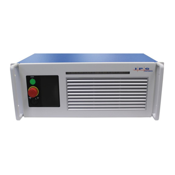
Page 34: Front Panel View
REMOTE Mode: The indicator is lit as soon as emission is enabled. This is removed by pulling on each side to access the filter element (refer to Table 18: 6. Front Bezel Panel Replacement Parts). PRODUCT DESCRIPTION | IPG PHOTONICS... -
Page 35: Rear Panel View
The protective caps should only be removed from the connectors immediately before optical cleaning and mounting in an adapter. IPG PHOTONICS | PRODUCT DESCRIPTION... -
Page 36: Machines With A Collimator
Cleaning of the protective window should be performed as needed using the same materials and techniques described in the “Optical Fiber Connector Inspection and Cleaning Guide” section. Figure 8: Fiber End with Collimator PRODUCT DESCRIPTION | IPG PHOTONICS... -
Page 37: Specifications
Refer to the SPECIFICATION YTTERBIUM FIBER LASER document included with this product. Environment Specifications Refer to the SPECIFICATION YTTERBIUM FIBER LASER document included with this product. External Layout and Dimensions Refer to the SPECIFICATION YTTERBIUM FIBER LASER document included with this product. IPG PHOTONICS | SPECIFICATIONS... -
Page 38: Unpacking Instructions
3. Open the primary box and remove the foam cover and store for later use. 4. Place the fiber on top of the unit and carefully lift it out of the box. IPG highly recommends two people to lift the unit at all times. -
Page 39: Unpacking Procedure For Wooden Crates
1. Place the package on a stable surface such as the floor or a large table. 2. IPG recommends using a powered screwdriver to remove all of the top screws securing the top lid 3. Remove the top lid and top foam insert 4. - Page 40 YLR-SERIES USER GUIDE 5. Place the fiber on top of the unit and carefully lift it out of the box. IPG highly recommends two people to lift the unit at all times. 6. Check the inventory of following items: Cover, AC Power Inlet(P45-001394) – Qty. 1 Strain relief (P40-002294) –...
-
Page 41: Figure 10: Unpacking Wooden Crates
YLR-SERIES USER GUIDE Figure 10: Unpacking Wooden Crates Primary Box Removing the Tie Wraps Lifting the Unit IPG PHOTONICS | UNPACKING INSTRUCTIONS... -
Page 42: Using Your Device
Follow all national and local requirements when wiring to the unit. Refer to the SPECIFICATION YTTERBIUM FIBER LASER document included with this product to determine your models power requirement. Figure 11: Power Cord Connection USING YOUR DEVICE | IPG PHOTONICS... -
Page 43: Interlock Description
For connectivity, the wiring and/or cabling must have an overall shield to ensure proper functionality. The shield is to cover over all conductors and terminate at the unit where the conductors enter/exit the unit. IPG PHOTONICS | USING YOUR DEVICE... -
Page 44: Table 4: 24-Pin Connector Pinout
If one of the two discharging channels fails (single fault condition) the interlock response time will be increased to ≤1000 ms. To use this pin external guide beam control must be enabled (EEABC command). To use this pin external emission control must be enabled (ELE command). USING YOUR DEVICE | IPG PHOTONICS... -
Page 45: Initial Power-Up Sequence
7. Ensure that the air-cooling vents are unobstructed to allow proper cooling of the device. Verify that the external cooling unit is powered on (for water-cooled models). Interlock response time (500 ms under normal conditions) must be additionally considered to ensure the safe state of the device. IPG PHOTONICS | USING YOUR DEVICE... -
Page 46: Turning On The Device In Local Mode
13. Wait until the laser becomes active (The power output will be displayed as „Low‟ indicating the laser is ready.). 14. The laser is now ready for operation. You may now select proper operation mode. USING YOUR DEVICE | IPG PHOTONICS... -
Page 47: Control Modes Of Operation
Default Setting: To set “External Aiming Beam Control Enabled” send the command “EEABC” via RS-232 interface or select it in setting menu using Touch-screen display. To set “External Aiming Beam Control Disabled” send the command “DEABC” via RS-232 interface or change it in settings menu using Touch-screen display. IPG PHOTONICS | USING YOUR DEVICE... -
Page 48: Operation Modes
Gate and External (Analog) Power Control. The main difference between sub-modes of operation is how the laser power is set and the laser emission is switched on/off: Continuous Mode (PULSE mode disabled) laser generates CW emission (except for Gate mode). USING YOUR DEVICE | IPG PHOTONICS... - Page 49 Pulses can be started by emission On command/signal (when Gate Mode is disabled) or by “gate” signal applied to Pins 15-16 of External Interface Connector (when Gate Mode is enabled). Waveform Mode cannot be selected if either External (Analog) Control or Modulation Mode is enabled. IPG PHOTONICS | USING YOUR DEVICE...
-
Page 50: Touch-Screen Display
Indicates the state of the guide laser control: “Internal” or “External Setpoint Bar: Touch “Set”, drag your finger up or down to set the required value. Press “Lock” when finished Function described lower in table. USING YOUR DEVICE | IPG PHOTONICS... -
Page 51: Figure 14: Submenu Menu Screens
Power Control Bar function (“Set” will then be displayed). Pressing “Set” will change the power to the new setpoint and lock the Power Control Bar. Green dot will light when pressed to turn on the Guide Beam IPG PHOTONICS | USING YOUR DEVICE... - Page 52 Enable / Disable Gate mode Enable / Disable External Guide Laser control Enable / Disable External Analog Power control Return to previous screen Enable / Disable Modulation mode Enable / Disable External Emission control USING YOUR DEVICE | IPG PHOTONICS...
- Page 53 Waveform Setting Mode Return Enables/Disables Waveform Pulse Mode Single Pulse / Pulse Sequence UP/DOWN Arrows scroll to select a program from memory Selected program in memory Transfers selected program to Waveform the laser. Mode IPG PHOTONICS | USING YOUR DEVICE...
- Page 54 Preview Screen. UP/DOWN Arrows scroll to select a program from memory Return to previous screen Pulse Program Preview Screen UP/DOWN Arrows scroll to select a program from memory Return to previous screen USING YOUR DEVICE | IPG PHOTONICS...
- Page 55 Cancel and return to previous screen Enter Repetition Rate in Hertz (Hz) range is 1 to 5000 Hz in 1 Hz increments Accept Repetition Rate Cancel and return to previous Rep Rate screen 10 Hz IPG PHOTONICS | USING YOUR DEVICE...
-
Page 56: Computer Interface / Commands
The commands are shown here as all uppercase for clarity; the actual commands are not case sensitive. A space character is also shown between the command and parameter for clarity. The space is not required. COMPUTER INTERFACE / COMMANDS | IPG PHOTONICS... - Page 57 Enable Modulation – Enables the modulation control input. “EMOD” EMOD Sent: Response: “EMOD” Stop Emission – Stops emission. “EMOFF” EMOFF Sent: Response: “EMOFF” Only for QCW Laser Models Models with Pulse Shaping Option Only IPG PHOTONICS | COMPUTER INTERFACE / COMMANDS...
- Page 58 Note: If the Key Switch is in the Remote position, a waveform Name[Test1]” configuration will be automatically executed before a response is returned “RBAUD” RBAUD Read Baud Rate Sent: Response: “RBAUD: 5 | 9600” QCW Models Only Models with Pulse Shaping Option Only COMPUTER INTERFACE / COMMANDS | IPG PHOTONICS...
- Page 59 The response will be the command echoed back, followed by a delimiter of “: “, (Indicates that the minimum then the minimum current as a percentage of the maximum. setpoint is 10.0 %) IPG PHOTONICS | COMPUTER INTERFACE / COMMANDS...
- Page 60 (ms). (Indicates that the pulse width is 5.5 ms) Read Serial Number – Reads the serial number of the device. Sent: “RSN” Response: “RSN: 6103081” PULSE MODE ONLY GATE MODE ONLY COMPUTER INTERFACE / COMMANDS | IPG PHOTONICS...
- Page 61 “ERR: Out of Range” or “ERR: Duty cycle too Range” high“. (The pulse width is unchanged) Sent: “SDC 8” “ERR: Duty Response: cycle too high” (The pulse width is unchanged) GATE MODE ONLY IPG PHOTONICS | COMPUTER INTERFACE / COMMANDS...
- Page 62 If the Key Switch is in the Remote position, a waveform configuration will be automatically executed before a response is returned Models with Pulse Shaping Option Only COMPUTER INTERFACE / COMMANDS | IPG PHOTONICS...
- Page 63 Hardware Emission Control Enabled Normal operation Bit 19 Power Supply Failure Front Panel Display is Unlocked Bit 20 Front Panel Display is Locked Keyswitch in ON position Bit 21 Keyswitch in REM position QCW MODELS ONLY IPG PHOTONICS | COMPUTER INTERFACE / COMMANDS...
-
Page 64: Table 9: Interface Commands
IP address for the laser. Unlock Front Panel – Unlocks touch-screen display on the “UFP” Sent: Response: “UFP” front panel of the laser. Table 9: Interface Commands Models with Pulse Shaping Option Only QCW Models Only COMPUTER INTERFACE / COMMANDS | IPG PHOTONICS... -
Page 65: Pulse Shaping Software Option
YLR-SERIES USER GUIDE Introduction The optional Pulse Shaping software was developed to aid users of IPG mid-power lasers in creating effective pulse shapes to meet the ever-changing requirements of their applications. IPG PHOTONICS | PULSE SHAPING SOFTWARE OPTION... -
Page 66: Pc Host Requirements
Stop Bits: Parity: None Flow Control: None Table 11: RS-232 Parameters Installing the Software To install this software package, run PSG installer as it will create a new folder with the pulse editor program. PULSE SHAPING SOFTWARE OPTION | IPG PHOTONICS... -
Page 67: Computer Configuration Procedure
2. Click Session->Serial Port 3. Enter the Com port the is attached to the laser, then click Connect 4. Ensure the connection is successful, and the status is displayed in the Connection indicator: Port:<COMx>~Good~ IPG PHOTONICS | PULSE SHAPING SOFTWARE OPTION... -
Page 68: Table 12: Configuring The Local Area Connection For Ethernet
Assign the IP address to 10.0.0.x (x can not be 10 as 10.0.0.10 is the default IP address of the Laser). Assign the Subnetmask to its default setting to 255.0.0.0 by clicking on the Textbox. Pres the “OK” command button to accept these manual changes. PULSE SHAPING SOFTWARE OPTION | IPG PHOTONICS... -
Page 69: Quick Start Guide
18. Click Laser Operation ->Write Sequence, then select an empty slot, click Write Sequence and enter a unique name, then click OK. 19. Create more programs (Pulse Sequences) required for your applications. Up to 100 sequences can be stored in the laser Pulse Sequence library. IPG PHOTONICS | PULSE SHAPING SOFTWARE OPTION... -
Page 70: Pulse Generator (Waveform Mode)
Load CSV Profile: Loads a and display comma- separated format pulse profile from the host machine Save CSV Profile: Saves a comma- separated format pulse profile from the host machine, this option only saves the effective pulse, and ignores unused time segments and LB and RB buffers. PULSE SHAPING SOFTWARE OPTION | IPG PHOTONICS... -
Page 71: Table 14: Psg Pulse Editor Sub-Menu Screens
Pulse Width: Current pulse width of the pulse in the chart Energy: Current pulse energy for the pulse in the chart Time: Current time coordinate of the mouse pointer Emission: Current time coordinate of the mouse pointer IPG PHOTONICS | PULSE SHAPING SOFTWARE OPTION... - Page 72 Due to the digitized nature of the pulses, approximations are used to compute modulations, so modulation step values, especially the very small ones may not have an effect. It is recommended to save original pulse or use the Snapshot interface while manipulating the pulse so it‟s easy to compare the modulated pulse against the original. PULSE SHAPING SOFTWARE OPTION | IPG PHOTONICS...
- Page 73 Due to the digitized nature of the pulses, approximations are used to compute modulations, so modulation step values, especially the very small ones may not have an effect. It is recommended to save original pulse or use the Snapshot interface while manipulating the pulse so it is easy to compare the modulated pulse against the original. IPG PHOTONICS | PULSE SHAPING SOFTWARE OPTION...
- Page 74 Due to the digitized nature of the pulses, approximations are used to compute modulations, so modulation step values, especially the very small ones may not have an effect. It is recommended to save original pulse or use the Snapshot interface while manipulating the pulse so it is easy to compare the modulated pulse against the original. PULSE SHAPING SOFTWARE OPTION | IPG PHOTONICS...
-
Page 75: Table 15: Sequence Editor Menu Screen
Name: Names of the current sequence Repeats: The number of repeats for the current sequence Infinite Repeats: Toggles infinite number of sequence repeats Intervals: Sets the time interval between each global repeat Reset: Resets all controls IPG PHOTONICS | PULSE SHAPING SOFTWARE OPTION... - Page 76 Add: Adds a sequence step at the end of the sequence, or add the very first step Sequence Steps: Current number of sequence steps / Maximum allowable Average Power: Current maximum average power/ Maximum allowable Profile Memory: Current pulse memory utilization/ Maximum allowable PULSE SHAPING SOFTWARE OPTION | IPG PHOTONICS...
-
Page 77: Table 16: Remote Control Menu Screen
If enabled when the laser‟s key switch is in Remote, it will prevent enabling the guide beam from PSG If enabled when the laser‟s key switch is in Remote, it will prevent starting emission from PSG IPG PHOTONICS | PULSE SHAPING SOFTWARE OPTION... -
Page 78: Pulse Editing
6. In the Editing panel, select the “add arc” tool , then drag and drop and existing pulse line to create different variation of an arc shape replacing the pulse line. PULSE SHAPING SOFTWARE OPTION | IPG PHOTONICS... -
Page 79: Shifting A Pulse
1. Using two instances of PSG: At least one of which has to be started in an Offline session, then the two application windows can be compared side to side. 2. The Snapshot Interface: This interface allows comparison of two pulses on the same chart: IPG PHOTONICS | PULSE SHAPING SOFTWARE OPTION... -
Page 80: Pulse Storage And Recall
The following is the general format of a Pulse profile in a CSV format, consisting of tags and data values. Required (header) tags: [S] - Sample time in ms [L] - Number of samples [D] - Start of comma separated percent emission data PULSE SHAPING SOFTWARE OPTION | IPG PHOTONICS... -
Page 81: Single Pulse Activation
9. After the configuration is complete, click Return twice to go back to the main page. Then click Emission, and then click OK to confirm and start countdown. The selected pulse will be emitted after the countdown. Click Emission again to clear the status. IPG PHOTONICS | PULSE SHAPING SOFTWARE OPTION... -
Page 82: Sequence Editing
In the top menu, select File->Save Sequence, then select a name and path for the saved sequence. To recall, select File->Load Sequence from the top menu then select the name and path of the file to load. PULSE SHAPING SOFTWARE OPTION | IPG PHOTONICS... -
Page 83: Pulse Sequence Activation
1. To start the interface, select Remote Control from the top menu Use the Setup panel to enable the waveform (pulse) mode, select the pulse or sequence mode, select a pulse or sequence then configure the laser. IPG PHOTONICS | PULSE SHAPING SOFTWARE OPTION... -
Page 84: Troubleshooting
RESULT: The power supply and laser emission will be switched off CAUSE: This means that digital data communication with the laser module inside the device is broken. POSSIBLE SOLUTION: Try to reset the error and if it appears again please contact IPG Photonics for assistance... -
Page 85: Table 17: Error Messages And Status Bits
POSSIBLE SOLUTION: Neither reset command (“RERR”) nor restart of the device will clear this error. Contact IPG Photonics for assistance. Be ready to read the Module Error Code (“RMEC” command) from the laser and submit it to an IPG Technical Support Specialist. -
Page 86: Service
IPG product, please call the Customer Service department. If you cannot resolve the issues by using this User‟s Guide or over the telephone with our technical support group, you may need to return the product to IPG. See PRODUCT RETURNS section for more details. -
Page 87: Table 18: Replacement Parts
Filter Media P45-004679 and P45-004704 Fuse T 10A 250VAC 3U AC P40-001743 Fuse T 15A 250VAC 3U WC, 4U AC (CW and P40-001564 QCW), 6U AC Table 18: Replacement Parts Refer to Laser Model Designation Codes IPG PHOTONICS | SERVICE... -
Page 88: Optical Fiber Connector Inspection And Cleaning Guide
(Figure 19: Fiber Quartz Block Inspection illustrates possible fiber failures). IPG Photonics is not responsible for any damages due to contaminated connectors. Tampering with the fiber connectors without training by IPG will void the warranty. -
Page 89: Figure 15: Fiber Connector Mounted On Ipg Microscope
6. Use light source to illuminate the face of the connector so that the light is reflected from the surface of the microscope. This is achieved if you see a bright golden shine from the IPG (yellow cable) connector end-face or a blue surface for the connector (Figure 19). - Page 90 13. Repeat above cleaning steps until all contamination is removed. This cleaning procedure can be stopped at any time if a good result has already been achieved. After fiber connector is clean use compressed air to clean the protective sleeve and install onto the connector. SERVICE | IPG PHOTONICS...
-
Page 91: Figure 17: Fiber End-Face Cleaning
CAUTION: It is hereby stated that damage to the fiber connector can occur due to mishandling, the use of incorrect cleaning procedures, or chemicals for cleaning. This is not covered by the warranty. Figure 17: Fiber End-face Cleaning Start to clean with even pressure. Drag in only one direction. IPG PHOTONICS | SERVICE... -
Page 92: Figure 18: Installing The Fiber
The connector is locked in position by a bayonet that also ensures correct orientation. The safety interlock system connects only when the bayonet is closed, via the two contact rings of the connector. When managing fiber do not exceed the maximum bend radius is 100mm unstressed and 200mm stressed. SERVICE | IPG PHOTONICS... -
Page 93: Figure 19: Fiber Quartz Block Inspection
YLR-SERIES USER GUIDE Figure 19: Fiber Quartz Block Inspection 1. Quartz Block 2. Fiber Cladding 3. Fiber Core Surface Damage Coating Damage Scratches IPG PHOTONICS | SERVICE... -
Page 94: Warranty
Products meet IPG Product specifications for newly manufactured Products. The Buyer must give prompt notification to IPG of any claim under the warranty in writing. IPG has no responsibility for warranty claims more than 30 days after the Buyer discovers or becomes aware of the claimed defect. Buyer is responsible for providing appropriate utilities and operating environment as stated in the operating manual and the specifications. -
Page 95: 46Bsoftware
1. General. The software, documentation and any fonts accompanying this License whether on disk, in read only memory, on any other media or in any other form (collectively the “IPG Software”) are licensed, not sold, to you by IPG Laser GmbH and its affiliates (“IPG”) for use only under the terms of this License, and IPG reserves all rights not expressly... - Page 96 No amendment to or modification of this License will be binding unless in writing and signed by IPG. Any translation of this License is done for local requirements and in the event of a dispute between the English and any non-English versions, the English version of this License shall govern.
- Page 97 You have acquired a device ("EQUIPMENT") that includes software licensed by IPG Photonics Corporation or its affiliates (collectively, “IPG”) from an affiliate of Microsoft Corporation ("MS"). Those installed software products of MS origin, as well as associated media, printed materials, and "online" or electronic documentation ("SOFTWARE") are protected by international intellectual property laws and treaties.
- Page 98 17. Additional Software/Services. This EULA applies to updates, supplements, add-on components, product support services, or Internet-based services components ("Supplemental Components"), of the SOFTWARE that you may obtain from IPG, MS, Microsoft Corporation or their subsidiaries after the date you obtain your initial copy of the SOFTWARE, unless you accept updated terms or another agreement governs.
- Page 99 For product support, please refer to IPG support number provided in the documentation for the EQUIPMENT. Should you have any questions concerning this EULA, or if you desire to contact IPG for any other reason, please refer to the address provided in the documentation for the EQUIPMENT.
-
Page 100: Product Returns
Speak to IPG Service Manager for the amount authorized under the required purchase order. 3. All requests for repair or replacement under this warranty must be made to IPG within 30 days after discovery of the defect (but not later than 7 days after warranty expiration). -
Page 101: Returns To Germany
Buyer for any charges as stated above. 5. Returns for credit will not be accepted unless authorized in advance, in writing by IPG Laser, in accordance with IPG Laser‟ Terms and Condition, including the warranty provisions. In most cases, restocking fees will apply. -
Page 102: Glossary
Millimeter = 10 meters Megahertz = 10 Hertz mrad Milliradian = 10 radians (geometry) Root mean square or quadratic mean QCW Quasi-Continuous wave (operating mode) TCP Transmission control protocol VAC Voltage alternating current Watts (power) GLOSSARY | IPG PHOTONICS...
Need help?
Do you have a question about the YLR Series and is the answer not in the manual?
Questions and answers
内控和外控模式下触摸显示屏,触摸时没有反应。start按键也没反应,指示灯不亮。
The IPG YLR Series touchscreen may be unresponsive, the start button may not respond, and the indicator light may not illuminate due to an Optical Interlock (Bit 3300) error. This occurs if the delivery fiber cable is mechanically damaged or the output connector is not properly plugged into an appropriate optical head. The internal main power supply is automatically switched off in this case.
To resolve this issue:
1. Send a reset error command (“RERR”).
2. If the message does not disappear, contact an IPG Photonics representative for assistance.
This answer is automatically generated
@Mr. Anderson 如何联系 IPG Photonics 代表寻求帮助。