Table of Contents
Advertisement
M2B+ Controller
Write Down Your Serial Numbers Here For Future Reference:
_________________________
_________________________
_________________________
We are committed to a continuing program of product improvement.
Specifications, appearance, and dimensions described in this manual are subject to change without notice.
DCN No. ____________
© Copyright 2007
All rights reserved.
Chapter 1: Safety
M2B+ Controller
Part Number: 682.92011.00
Bulletin Number: SC1-630.8
Effective: 12/10/07
_________________________
_________________________
_________________________
1 of 65
Advertisement
Table of Contents

Subscribe to Our Youtube Channel
Summary of Contents for Sterling M2B+
- Page 1 M2B+ Controller M2B+ Controller Part Number: 682.92011.00 Bulletin Number: SC1-630.8 Effective: 12/10/07 Write Down Your Serial Numbers Here For Future Reference: _________________________ _________________________ _________________________ _________________________ _________________________ _________________________ We are committed to a continuing program of product improvement. Specifications, appearance, and dimensions described in this manual are subject to change without notice. DCN No.
- Page 2 M2B+ Controller Shipping Information Unpacking and Inspection You should inspect your equipment for possible shipping damage. Thoroughly check the equipment for any damage that might have occurred in transit, such as broken or loose wiring and components, loose hardware and mounting screws, etc. In the Event of Shipping Damage According to the contract terms and conditions of the Carrier, the responsibility of the Shipper ends at the time and place of shipment.
-
Page 3: Table Of Contents
M2B+ Controller Table of Contents CHAPTER 1: SAFETY..............6 How to Use This Manual ..................... 6 Safety Symbols Used in this Manual ..............6 Warnings and Precautions ..................7 Responsibility ......................7 CHAPTER 2: FUNCTIONAL DESCRIPTION ......9 Models Covered in This Manual.................. 9 General Description.................... - Page 4 M2B+ Controller CHAPTER 5: ADVANCED OPERATION ......... 29 Using the Analog Remote Input ................29 Retransmission Analog Signal .................. 30 Setting the Analog Signal Source to FLOW ............31 Using Analog Output for Heating and Cooling.............31 Using the Flow Monitor....................32 Programming the Alarms...................
- Page 5 M2B+ Controller User Interface......................56 Temperature Sensor Inputs.................57 Flow Sensor Inputs....................57 System Inputs......................57 Optional Analog Output Modules ................57 Menu Structure* ......................58 Control Board Layout ....................64 DAC Board Layout (Optional)..................64 Technical Assistance....................65 Parts Department ....................65 Service Department.....................65 Sales Department....................65 Contract Department ...................65 Chapter 1: Safety 5 of 65...
-
Page 6: Chapter 1: Safety
M2B+ Controller Chapter 1: Safety How to Use This Manual Use this manual as a guide and reference for installing, operating, and maintaining your equipment. The purpose is to assist you in applying efficient, proven techniques that enhance equipment productivity. This manual covers only light corrective maintenance. -
Page 7: Warnings And Precautions
M2B+ Controller Warnings and Precautions Our equipment is designed to provide safe and reliable operation when installed and operated within design specifications, following national and local safety codes. To avoid possible personal injury or equipment damage when installing, operating, or maintaining this equipment, use good judgment and follow these safe practices: Follow all SAFETY CODES. -
Page 9: Chapter 2: Functional Description
M2B+ Controller Chapter 2: Functional Description Models Covered in This Manual This manual provides operation, installation, and maintenance instructions for the M2B+ Controller. The M2B+ Controller is available for use with several models of temperature control units (TCUs). A separate manual describes operation, installation, and maintenance instructions for the TCU itself. -
Page 10: General Description
M2B+ Controller General Description The M2B+ is a microprocessor-based process controller designed for use with temperature control units. The M2B+ monitors and maintains the temperature of the fluid in any given process to a selected setpoint using a unique proportional integral derivative (PID) auto- tuning program. -
Page 11: Standard Features
M2B+ Controller Standard Features • PID Control for both heating and cooling • 4 line x 20 character LCD Display Screen • Setpoint, To Process, From Process, and DT displays • System status • Password protection • Selectable sensor types (Type K, J, & T thermocouples; 100 ohm and 1000 ohm RTDs) •... -
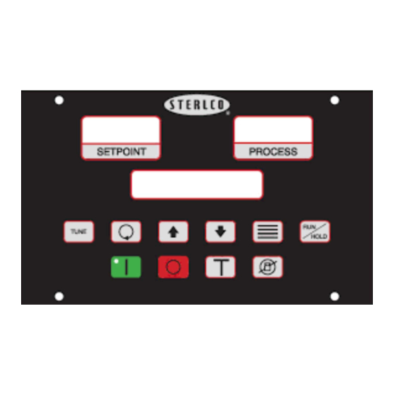
Page 12: Panel Layout And Keypad
M2B+ Controller Panel Layout and Keypad Figure 1 on page 15 for an illustration of the control panel and its buttons. The LCD backlight lights up whenever any key is pressed. The backlight turns off after five minutes if no other key activity occurs. -
Page 13: Lcd Messages
M2B+ Controller LCD Messages Autotuning. Appears while tuning is in process. High Water Alarm. Appears if the option is selected and the switch is closed Water Pressure/Low Level Alarm. Appears when the Low Water Pressure switch is open or the optional Low Water switch is closed. Auto Vent Indicator. -
Page 14: Keypad
M2B+ Controller Keypad Four keys, ‘Index’, ‘Up’, ‘Down’, and ‘Enter’ are used primarily to gain access to the menu structure and modify the controller’s parameters and features. The remaining six keys are used to direct the controller to start or stop a process. Button Function •... - Page 15 M2B+ Controller Button Function • When the system is first powered-on and the “Power Available - System Off” message is displayed, pressing the VENT key will turn on the Vent Output for a period of 8 seconds. The message “VENT” will be displayed during this period. •...
-
Page 16: Menu Structure
M2B+ Controller Menu Structure The parameter menu structure is organized into three basic menus: Primary, Secondary, and Secure. To access the menus, press the Index button until the menu label appears in the second line of the LCD display. Additional menus display when an option is selected; however, the options are non-functional unless the appropriate menu option or option board has been installed. -
Page 17: Passwords And Security
M2B+ Controller Passwords and Security The controller provides four levels of security. Depending on the security level, some or all of the setup menus may be locked. The security level must be changed in order to unlock these menus. The current security level is displayed in the lower right corner of the menu display. The default security level is 3. -
Page 19: Chapter 3: Installation
M2B+ Controller Chapter 3: Installation Location Mount the instrument in a location that will not be subject to excessive temperature, shock or vibration. All models are designed for mounting in an enclosed panel. When properly mounted in an enclosed panel using a gasket at the panel/controller interface, the keypad can be washed down with water. -
Page 21: Chapter 4: Basic Operation
M2B+ Controller Chapter 4: Basic Operation Turning the Power On When AC power is first applied to the unit, the following sequence of events will occur: 1. The LCD backlight lights up. 2. The LCD displays dashes: LEDs have all segments on. 3. -
Page 22: Starting And Stopping Water Tcus
M2B+ Controller Starting and Stopping Water TCUs Starting the Unit (Local) Press the Start button to begin the following sequence of events: 1. The green LED inside the Start button lights up. 2. The LCD backlight lights up. 3. The Pump Output turns on. 4. -
Page 23: Starting And Stopping Hot Oil Tcus
M2B+ Controller Starting and Stopping Hot Oil TCUs Starting the Unit (Local) Press the Start button to begin the following sequence of events: 1. The green LED inside the Start button lights up. 2. The LCD backlight lights up. 3. The Pump Output turns on. 4. -
Page 24: Starting The Unit (Remote)
M2B+ Controller button is released, at which time the 30-second time-out will restart. After 30-seconds, the system will recycle to the “Power Available/System OFF” state. Starting the Unit (Remote) REMOTE START option is similar to the water process sequence. Closure of pins 5 and 6 of header J6 initiates the start sequence. -
Page 25: Manual Tuning (Zeigler-Nichols Pid Method)
M2B+ Controller Manual Tuning (Zeigler-Nichols PID Method) This tuning method may be used if the spread between ambient temperature and process operating temperature is small. For best results, use a recording device when tuning with this method. 1. Disable the cooling valve by removing the output signal to the device. For solenoid valves, remove plug from the solenoid. -
Page 26: Selecting A Local Probe
M2B+ Controller Selecting a Local Probe The controller has two standard temperature probe inputs for delivery (to process) and return (from process). The probes are typically set up at the factory, but they can be re-configured in the field. To set up this feature you must have access to the Secure Menu. See Section 2-6 on page 16 to review accessing the Secure Menu. -
Page 27: Setting Up Cascade Control
M2B+ Controller Setting Up Cascade Control The controller is provided with an internal cascade control feature. Cascade control is used to enable a process having multiple lags to be controlled with the fastest possible response to process disturbances. The system uses a remote control probe in the downstream process and a local delivery and return probe in the TCU. -
Page 28: Adjusting The Automatic Venting Timer
M2B+ Controller Adjusting the Automatic Venting Timer When the Auto Vent Cycle Timer is set, the controller will open the venting valve for the set time at the startup of the unit. The Auto Venting Timer can be turned off, or it can be set to a specified time period. -
Page 29: Chapter 5: Advanced Operation
M2B+ Controller Chapter 5: Advanced Operation Using the Analog Remote Input This feature is typically setup at the factory, but can be installed as a retrofit in the field. It is used to accept a remote analog setpoint value or flow value. If the analog signal is set up for remote setpoint input, the Up and Down arrow keys are locked out for changing the setpoint at the controller. -
Page 30: Retransmission Analog Signal
M2B+ Controller Retransmission Analog Signal This feature is typically set up at the factory, but it can also be installed as a retrofit in the field. It is used to transmit an analog signal for process temperature, setpoint temperature, and flow. -
Page 31: Setting The Analog Signal Source To Flow
M2B+ Controller Setting the Analog Signal Source to FLOW If the analog signal source is set to “FLOW,” follow steps 1 through 15 on page 30, and then complete the following procedure: 1. Press the Index button until the display reads “Remote Input.” 2. -
Page 32: Using The Flow Monitor
M2B+ Controller Using the Flow Monitor The controller is set up to accept a pulsed or current input from a flow sensor. The controller translates the pulse or current into either gpm (gallons per minute) or lpm (liters per minute). If the flow sensor is of the pulsed variety, it is connected to block J1 on the main controller board. -
Page 33: Programming The Alarms
M2B+ Controller Programming the Alarms The controller is set up to monitor both critical and non-critical operations within the process. Based on the severity of the condition, the controller will alarm and perform a specific function based on the type of unit being controlled. If an alarm is tripped, the LCD display will flash the backlight and if an audible alarm is present, turn it on. -
Page 34: Flow Alarm
M2B+ Controller Flow Alarm This alarm is used to monitor the flow rate input from either a pulse or analog style flow meter. Once the Flow Monitor is turned on (in the Secure Menu; Flow Monitor = PUL or CUR) either a low flow alarm or high flow alarm or both can be set up. Use the following procedure to set up the Flow Alarm: 1. -
Page 35: Low Fluid Level Alarm
M2B+ Controller Low Fluid Level Alarm This factory-set alarm occurs when the low level switch is in a closed condition. This is not a critical alarm and will reset once the condition is cleared. For water TCUs the Low Level alarm disables the heater and the pump motor outputs. -
Page 36: Using The Second Setpoint Function
M2B+ Controller Using the Second Setpoint Function With this function, the user can send the controller a dry contact closed signal to activate the second setpoint. Opening the dry contact causes the controller to revert to the primary setpoint. To reinitiate the second setpoint, the switch must be closed again. Use the following procedure to enable the second setpoint function: 1. -
Page 37: Changing The Temperature Display Units
M2B+ Controller Changing the Temperature Display Units The controller is set up to display the temperature, and all related temperature settings, in either degrees Fahrenheit or degrees Celsius. Use the following procedure to change the display units: 1. Press the Index button two times to access the Secondary menu. 2. -
Page 38: Using The Elapsed Time Meter
M2B+ Controller Using the Elapsed Time Meter The controller is equipped with an elapsed time meter that keeps track of the time that the pump motor has run in hours. The meter is enabled or reset in the Secure menu and viewed in the Primary menu. -
Page 39: 5-10 Programming Ramp/Soak
M2B+ Controller 5-10 Programming Ramp/Soak The controller has a 16-segment, front-face programmable Ramp/Soak feature. Unused alarms can be programmed as a segment. Caution! Do not attempt to auto-tune the controller during a ramp/soak program. The Tune button will not function during this process. Instead of requiring the operator to calculate an approach rate, the controller does the calculation automatically. - Page 40 M2B+ Controller Use the following procedure to program the Ramp/Soak functions: Starting Ramp/Soak Programming: 1. Press the Index button two times to access the Secondary menu. 2. Press the Enter button. 3. Press the Index button until the display reads “Prog Ramp/Soak.” 4.
-
Page 41: Controlling Ramp/Soak
M2B+ Controller Controlling Ramp/Soak The Secondary Menu parameter “Prog Ramp/Soak = “ must be set to ‘ON’ in order to control the ramp/soak operation. Press the ‘RUN/HOLD’ button on the panel to put the ramp/soak operation into the Run state. The LCD display will change from “Running”... -
Page 42: 5-11 Setting The Approach Rate
M2B+ Controller 5-11 Setting the Approach Rate The controller is provided with a selectable up and down ramp to setpoint feature, located in the secure menu. The time base is in minutes and is adjustable from off to 99 minutes in 1 minute increments. -
Page 43: 5-15 Calibrating The T/C, Rtd, And V Inputs
M2B+ Controller 5-15 Calibrating the T/C, RTD, and V Inputs This calibration procedure describes the operator procedures for calibrating the Controller Sensor Input (T/C and RTD) and the Analog input (V). Use the following procedure to calibrate all three sensor inputs: 1. - Page 44 M2B+ Controller Calibrating the RTD Input Note: This RTD calibration procedure requires a 0 to 1000 ohm Decade Resistance box to calibrate this analog input circuit. Once the circuit is calibrated, either a 100 ohm RTD or a 1000 ohm RTD can be selected for operation.
-
Page 45: 5-16 Accessing The Debug Menu
M2B+ Controller 5-16 Accessing the Debug Menu The controller has a troubleshooting tool in the secure menu. Use this menu to assist in debugging communications errors and flow sensor input errors. Use the following procedure to troubleshoot communications errors: 1. Press the Index button three times to access the Secure menu. 2. -
Page 46: 5-17 Reloading Factory Defaults
M2B+ Controller 5-17 Reloading Factory Defaults When factory default settings are reloaded, all special configurations (i.e., 4-20 ma scaling) will be lost. Please record menu variables before restoring the factory defaults. Restoring factory defaults for low-heat water TCUs can be accomplished by entering “Factory mode.”... -
Page 47: 5-18 Serial Communications Operation
M2B+ Controller 5-18 Serial Communications Operation The controller communicates with a host machine via an RS232 or RS485 communication link when the communication option card is installed in the J8 slot on the motherboard. There are two versions of this option card; one is populated with the ICs to support RS232, and the other is populated with the ICs to support RS485. -
Page 48: Modbus Protocol
M2B+ Controller MODBUS Protocol Every message sent from a MODBUS master to a slave on to the network contains a function code that represents the action the slave device should take in response to the message. So that a MODBUS master can read and write the controller parameters, setpoints, and status values in an Athena Temperature controller, the Athena implementation of the MODBUS protocol supports the following function codes: function 03 ($03) This function is used to read to one or more contiguous “holding registers”... - Page 49 M2B+ Controller Modbus Accessible Parameter Mapping. The customized controller allows access to (29) controller parameters and settings, which can be accessed in Integer Mode or Floating point mode. This is accomplished with (2) Point Address ranges, allowing data exchange in either integer or floating point format, for all controller parameters and settings.
- Page 50 M2B+ Controller MODBUS Function 03 Request. The format for a function 03 request is shown below. Device Function Code Register Address Number Of Words Address To Read 1 byte 1 byte containing $03 MODBUS Function 03 Request Example. Suppose you want to Read Delivery Temperature in Float 32 Bit IEEE Format, which has registers address of "4002"...
-
Page 51: Spi Protocol
M2B+ Controller SPI Protocol The Society of the Plastics Industry (SPI) communication protocol specifies a connection management Protocol, a packetized communication format, and communication error mechanisms passing commands and data between a host computer and a slave. A host computer initiates all communications. The protocol used corresponds to the 3.01 version of the SPI communication protocol specification dated October 1990. - Page 52 M2B+ Controller Bit 5 -Alarm, Low Temperature Bit 7 -Alarm, Low Pressure Bit 14 -Alarm, Phase Reversed or Lost (44H) Status, machine 2 poll-Returns the status of the machine as 16 flag bits in open format. The following bits are supported. The rest are set to 0. Bit 0 -Processing Bit 1 -Alarm, System Bit 2 -Alarm, Process...
-
Page 53: Chapter 6: Troubleshooting
M2B+ Controller Chapter 6: Troubleshooting This Troubleshooting section should be used in conjunction with the Troubleshooting section of the unit that the controller was supplied with. The problems listed below are displayed on the LCD and the action the user takes will depend on whether the alarm is critical or non- critical. - Page 54 M2B+ Controller Problem Possible Cause Solution Unit shuts down after running The Program End function is Change the value of “Prog through Ramp/Soak program incorrectly configured. End” from OFF to desired action at the end of the program. Security password set to Change security setting to gain Setpoint temperature does not lockout status...
-
Page 55: Operating Mode And Error Display Messages
M2B+ Controller Operating Mode and Error Display Messages Figure 5: Display Messages, Operational and Errors Message Type Display Presentation Description Normal Autotune Autotuning [ Normal Running Running [ Running. (High Heat and Cool shown is Normal) Normal RampSoak Rampsoak [ Alarm Alarm1/2 [LoFluid LVL] This Indicates Alarm Low Fluid Level... -
Page 56: Chapter 7: Appendix
M2B+ Controller Chapter 7: Appendix Electrical Specifications General Dimensions 5.5” X 9” X 4” Range of the Unit -30°F to 650°F Normal Operating Environment Operating Temperature Range 0° C to 60° C (LCD Display up-to 50° C) Humidity 0 to 95% RH (Non condensing) Storage Environment Storage Temperature Range -10°... -
Page 57: Temperature Sensor Inputs
M2B+ Controller Temperature Sensor Inputs Thermocouple Type J, K, and T ungrounded Thermocouple Types (Class 2) RTD Type 100Ω, 1000Ω RTD Type, 00385 COEF. 2 Wire (Class Measurement (Full Scale) Range -30 °F to 650°F Process/Setpoint Display Resolution 1° C, 1° F, 0.1° C, 0.1° F Measurement Accuracy ±... -
Page 58: Menu Structure
M2B+ Controller Menu Structure* Primary Menu Secondary Menu Secure Menu System Degrees (F/C) Security Level Monitor Temp Precision Unit Function Alarm 1 Low Alarm1 Cfg Tune% Reduction Alarm 1 High Alarm1 Mode Mold Offset PrgSeg#Remain Alarm1 Reset Return Offset PrgSeg# Time Alarm PwrIntr Delivery Offset PrgSeg# SetPt... - Page 59 M2B+ Controller Chapter 7: Appendix 59 of 65...
- Page 60 M2B+ Controller 60 of 65 Chapter 7: Appendix...
- Page 61 M2B+ Controller Chapter 7: Appendix 61 of 65...
- Page 62 M2B+ Controller 62 of 65 Chapter 7: Appendix...
- Page 63 M2B+ Controller Chapter 7: Appendix 63 of 65...
-
Page 64: Control Board Layout
M2B+ Controller Control Board Layout DAC Board Layout (Optional) 64 of 65 Chapter 7: Appendix... -
Page 65: Technical Assistance
M2B+ Controller Technical Assistance Parts Department Call toll-free 7am–5pm CST [ 800 ] 423-3183 or call [262] 641-8610, Fax [262] 641-8653 The ACS Customer Service Group will provide your company with genuine OEM quality parts manufactured to engineering design specifications, which will maximize your equipment’s performance and efficiency.
Need help?
Do you have a question about the M2B+ and is the answer not in the manual?
Questions and answers