Table of Contents
Advertisement
Advertisement
Table of Contents

Summary of Contents for Edge Products Insight Pro
-
Page 2: Table Of Contents
Table of Contents Read Me Safety Warning & Caution Safety Guidelines At a Glance Physical Overview - The Display Accessories Touch Screen Gestures Menu Icons Common Terms Getting Started Download the Ignition Update Software Using the Ignition Update Software Cable Installation Windshield Mount Installation Installing the Display Display Set Up... - Page 3 Diagnostics Read DTCs Clear DTCs Clear On Start Manual DPF Regeneration DPF Regeneration Explained Injector Balance Rates Performance Testing 0-60 & Quarter Mile Horsepower Data Log Data Logging Explained Retrieving Data Using MyStyle Records Records Explained Help Help Menu Explained Maintenance Manager Turn on Maintenance Manager Entering the Odometer Value Setting the Alert Threshold...
-
Page 4: Read Me
Read Me Safety Warning & Caution Throughout this User Manual you will see important messages regarding your safety or the protection of your vehicle. These messages are designated by the words WARNING, CAUTION, or NOTICE. WARNING A WARNING indicates a hazardous situation which, if not avoid- ed, will result in death or serious injury. -
Page 5: Safety Guidelines
Failure to do so could result in DEATH or SERIOUS INJURY. • Your Insight Pro device is compatible with third-party custom tuning software. Before installing third-party tuning software on your device, refer to the third-party tuning dealer/developer’s instructions and warnings, including any user manual or other written material, and your vehicle’s user manual. -
Page 6: At A Glance
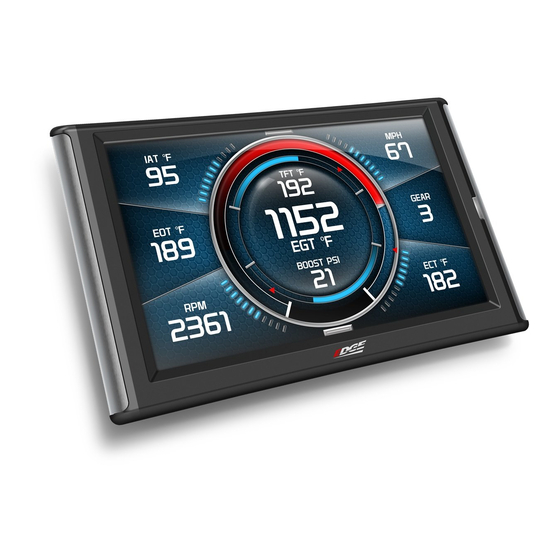
At a Glance Physical Overview - The Display Drop-down Menu Gauges Ambient Light Sensor Quick Link Menu Video HDMI Port Mount Receiver USB port At a Glance... -
Page 7: Accessories
Accessories Windshield Mount Suction Lever Adjustment Alcohol Wipe Dual-Tab Iso- Mount propyl OBDII to HDMI cable HDMI OBDII Mini USB Cable Zip-Ties At a Glance... -
Page 8: Touch Screen Gestures
Touch Screen Gestures Use these gestures to navigate and control the display. Press Hold & Drag The Press gesture is used The Hold & Drag gesture to select options, input is used to drag up or down values, enter menus, etc. menus, and scroll through menu items. Swipe The Swipe gesture is used to scroll through gauge screens. -
Page 9: Menu Icons
Menu Icons Icon What it does Home Brings you back to the home screen Background Changes the background Image Custom Color Opens the custom color picking menu Default Color Opens the default color picking menu Back Brings you back to the previous screen or menu Common Terms Term What it is... -
Page 10: Getting Started
Getting Started Download the Ignition Update Software STEP 1 - Go to our website: www.edgeproducts.com STEP 2 - Click the UPDATES tab located at the top of the webpage. STEP 3 - Scroll down to the IGNITION UPDATE option and click the DOWNLOAD button. -
Page 11: Using The Ignition Update Software
Using the Ignition Update Software A computer with internet access is required: STEP 1 - Double click the Ignition Icon on your desktop. STEP 2 - When asked, plug the display into the computer using the supplied USB cable. STEP 3a - If an update is available, click YES to continue. NOTICE! DO NOT unplug the display from the computer during an update. -
Page 12: Cable Installation
Cable Installation STEP 1 - Locate the On Board Diagnostics II (OBDII) port. (This connector is typically found directly below the driver side dash console.) STEP 2 - Plug the OBDII connector into HDMI the vehicle port. STEP 3 - Route the HDMI end up the driver side dash. -
Page 13: Installing The Display
Installing the Display STEP 1 - Plug the HDMI connector into the HDMI receptacle located on the back side of the display. STEP 2 - Align the Dual Tabs on the Mount with the mount receiver on the back side of the display, then slide it into place. -
Page 14: Display Set Up
Display Set Up OEM Selection Menu Once the installation is complete, and you first plug the device into the OBDII port, the OEM selection menu will appear. OEM Selection Menu: Ford Chrysler / Dodge GM / Chevy Import EAS 12V Power Kit STEP 1 - Turn the vehicle to the ON or RUN key position. STEP 2 - Select one of the available options that applies: Ford Chrysler/Dodge... -
Page 15: Entering The Quick Link Menu
Entering the Quick Link Menu STEP 1 - Press the lower menu tab to enter the Quick Link Menu. STEP 2 - The Main Menu will appear. Choose a menu option, and Press the Icon to enter that feature menu. (Note: Each feature menu option is shown in detail later in this manual) Return to Home... -
Page 16: Entering The Pull Down Menu
Entering the Pull Down Menu STEP 1 - Press the upper menu tab to enter the Pull Down Menu. The following screen will appear: If notifications are active they will be listed here. These buttons toggle the power If multiple notifications are level which is displayed be- active at one time they will tween the two. -
Page 17: Changing The Default Background Image
Changing the Default Background Image STEP 1 - Enter the Pull Down Menu. STEP 2 - Press the Background icon. Each press of the icon will cycle through to the next image: Honey Comb Wild Fire Diamond Plate (Red/Blue/Green) Flash Scratched Simple Digital Camo White Wash... -
Page 18: Configuring The Home Screens
Configuring the Home Screens STEP 1 - Enter the Quick Link menu. STEP 2 - Press the Screen Layout Icon STEP 3 - Select either Layout 1 or Layout 2. Press to Screen Layout select a Background default Layout 1 - Master Background Layout 2 - Accelerometer image... - Page 19 Layout Options Master Digital Retro Switches Needles Accelerometer STEP 5 - Return to the Home screen. STEP 6 - Swipe horizontally to switch between your selected layouts. Display Set Up...
-
Page 20: Using The Switch Screen - Toggle Switches
Using the Switch Screen - Toggle Switches If you have purchased an Expandable Accessory System (EAS) Power Switch, you can use the Switch Screen to quickly toggle On or Off up to (4) different com- ponents (e.g. light bars, pumps, winch, etc.) For proper installation of the Power Switch, refer to the EAS Installation Manual. - Page 21 If you would like to customize a switch: STEP 1 - Touch and hold the switch for 3 second, then let off. A menu will appear. STEP 2 - Select each option and make your adjustments accordingly. The default name Allows you to for each Power select which...
-
Page 22: Individual Gauge Setup
Individual Gauge Setup STEP 1 - Press any gauge. STEP 2 - Select New PID Some Analog gauges allow Battery Voltage Please Refer you to change Select New PID to Alert its color Options Alert Settings Section for Gauge Color more info Describes the PID Information... -
Page 23: Calibrating Pitch, Roll, & G-Force Gauges
Calibrating Pitch, Roll, & G-Force Gauges Once the display has been installed, and is mounted in a semi- permanent position, the Pitch, Roll, & G-Force gauges will need to be calibrated. STEP 1 - Refer to Configuring the Home Screen section in this manual. Assign the Accelerometer screen layout to one of the DAQ screens. -
Page 24: Download And Install Mystyle Software
Download and Install MyStyle Software MyStyle is software that allows you to customize your display background image and manage your EAS devices. A computer with internet access is required: STEP 1 - Go to www.edgeproducts.com STEP 2 - Click the UPDATES tab, then Mystyle DOWNLOAD. -
Page 25: Adding Custom Background Images
Adding Custom Background Images This section describes how to add personalized photos or pictures to your display using a computer. STEP 1 - Double-click the MyStyle icon on your desktop. STEP 2 - Connect the display using the supplied USB cable. When a display is plugged in, an image of the display will appear with a 9 digit number. -
Page 26: Performance Tuning
Modifications to your vehicle through third-party tuning software may result in death or serious injury, property damage, or both. The Insight Pro is used to monitor vital engine data during a vehicle’s operation. The Insight Pro is a data monitoring device that can be used to store and load to your vehicle custom tuning files that are developed by third-parties. -
Page 27: Custom Tuning Process - At A Glance
You will recieve a “Dealer Key” from them. The Insight Pro will read your vehicle’s Use Insight Pro to computer and save all the origional stock read vehicle stock files. -
Page 28: Read Vehicle Stock
Read Vehicle Stock The Insight Pro holds up to 4 custom tunes at a time. Before these custom tunes can be created, you will need to save the vehicle’s stock files. STEP 1 - Enter the Quick Link menu. STEP 2 - Press the Performance Tuning icon. -
Page 29: Loading Custom Tunes
STEP 2 - Once you have downloaded and installed Ignition to your computer, double click the icon to open the software. STEP 3 - Connect the Insight Pro to your computer using the supplied USB cable. (NOTE: Ignition will automatically recognize your device.) STEP 4 - When the “Update Now?”... - Page 30 STEP 6 - When the registration form appears, fill out all required information. STEP 7 - Click the submit button. STEP 8 - When the “Update Now?” screen re-appears in Ignition, select the Yes button. (NOTE: During the update process, your device will send the stock file data to the calibrator.) CAUTION: Do Not unplug the device until the update is complete.
-
Page 31: Programming Your Vehicle
Programming your Vehicle CAUTION CAUTION: Programming requires that the vehicle be parked and not moving. As such, make sure to park away from traffic or areas where the vehicle may impede access or exit. Programming may take several minutes and the vehicle can’t be started during this process. STEP 1 - Unplug all power consuming devices plugged into the cigarette lighter or other power ports. -
Page 32: Settings
Settings Accessory Options STEP 1 - Enter the Quick Link menu. STEP 2 - Press the Settings icon. STEP 3 - Press the Accessory Options button. Options Accessory Options Vehicle Options Alert Options Sound Duration - 3 sec Screen Layout STEP 4 - Select an option in which you would like to modify. - Page 33 STEP 5 - Select Camera Delay. Adjust the value using the arrows, then press Enter. Camera Delay WARNING Always drive carefully confirming the safety of the rear EXIT ENTER and surrounding conditions by looking directly with your Reversing the vehicle by only looking at the screen is eyes: dangerous as it may cause an accident or a collision with an object.
- Page 34 The CTS2 is designed to display the back-up camera when the vehicle is put into reverse. This feature allows you to specify how many seconds you would like the camera view to wait before it shows up on the display. NOTE: This feature is not available on all vehicle makes and models.
- Page 35 NOTE: 2007-09 Dodge trucks can be turned off using the key’s panic button. 2010 Dodge trucks can be turned off if the lock and panic buttons are pressed at the same time. WARNING Do not use the Tubo Cool Down Setup in an enclosed area. The engine will continue to tun and my produce fumes or exhaust that may be harmful in an enclosed area.
-
Page 36: Vehicle Options - Tire Size
Vehicle Options - Tire Size The display is capable of re-calibrating the MPH PID. In order for this to happen, you will need to enter a tire size. STEP 1 - Enter the Quick Link menu. STEP 2 - Press the Settings icon. -
Page 37: Alert Options
Alert Options STEP 1 - Enter the Quick Link menu. STEP 2 - Press the Settings icon. STEP 3 - Select Alert Options from the list. STEP 4 - Select a PID from the list. Press to toggle the Alert Options Alerts Off or On Alerts are Off Battery Voltage... -
Page 38: Sound Duration - Alerts
Sound Duration - Alerts STEP 1 - Enter the Quick Link menu. STEP 2 - Press the Settings icon. STEP 3 - Select Sound Duration from the list. STEP 4 - Adjust the time (in Sound Duration seconds) to the length of time an alert should sound. -
Page 39: Menu Time Out
Menu Time out This feature prevents the display from staying on for excess amounts of time. Once the time runs out, the display will return to the main gauge screen, then shut off. STEP 1 - Enter the Quick Link menu. STEP 2 - Press the Settings icon. - Page 40 Diagnostics Read DTCs When your PCM detects a problem with your vehicle it sets a trouble code, and most times a “Check Engine” light on your dash is activated. These codes can be retrieved and used to help diagnose specific issues. STEP 1 - Enter the Quick Link menu.
- Page 41 Clear DTCs This feature allows you to clear most DTCs. This will erase any codes currently set. If the codes come back we recommend you see a qualified mechanic who can accurately diagnose and repair the problem. STEP 1 - Enter the Quick Link menu. STEP 2 - Press the Diagnostics icon.
- Page 42 Manual DPF Regeneration Available on specific Diesel Trucks Only Manual regeneration allows you to manually clear out the Diesel Particulate Filter (DPF). Completing a manual regeneration cycle will clear the soot mass in the filter, and lower exhaust back pressure to improve exhaust flow. WARNING Maintain a safe distant from the exhaust during regeneration. Exhaust temperatures may be greater than 300C (572F) during service regeneration.
- Page 43 STEP 3 - Select the Manual Diagnostics Regen option. Trouble Codes Manual Regen STEP 4 - When prompted, Trans Relearn touch the screen to continue. Performance Tests Records NOTE: When manually initiating a regeneration cycle, some vehicles will require a drive cycle (i.e. you have to drive the vehicle some distance) while others may allow you to initate a Service Regeneration where you can leave the vehicle parked and the engine running.
- Page 44 DPF Regeneration Explained CAUTION Exhaust temperatures may be greater than 300C (572 F) during service re- generation. Due to the elevated temperatures during this procedure, open the hood and keep the front of the vehicle away from anything impeding air flow to the radiator. DPF REGENERATION If you own a newer diesel powered vehicle, your vehicle is equipped with a diesel particulate filter (DPF).
- Page 45 Injector Balance Rates Available on specific GM/Chevy Trucks Only Injector Balance Rates are used to determine if all injectors are operating within the correct tolerances. If you are experiencing a misfire, knock, excessive smoke, or rough running conditions with no DTCs, this option can help identify faulty injectors. The balance rates are the fuel adjust- ments for each individual cylinder based on the variations in engine crankshaft speed.
- Page 46 Performance Testing 0-60 & Quarter Mile WARNING Follow all traffic laws when conducting performance testing. Failure to obey traffic laws could result in traffic accidents, serious injury or death, and/or damage to the vehicle. Performance tests can be helpful for measuring performance gains after vehicle modifications have been made. The results recorded during these test will likely differ from what you’ll see on a drag-strip or other racing venues.
- Page 47 Horsepower NOTE: Before using the Horsepower test, the vehicle weight (aka curb weight) must be entered first. The curb weight is the total weight of a vehicle with stan- dard equipment, all necessary operating consumables (e.g., motor oil, coolant), a full tank of fuel, with no passengers or cargo. STEP 1 - Enter the Quick Link menu.
- Page 48 Data Log Data Logging Explained The data logging feature allows you to record all of the available PID data on your display. This information can be retrieved and viewed using the MyStyle software package. NOTE: The display also runs background tasks which are also record- ed.
- Page 49 Retrieving Data Using MyStyle This section describes how to retrieve the data recorded during a Data Logging recording session. If you have not yet installed MyStyle refer to the Display Set Up section of this manual. STEP 1 - Double-click the MyStyle icon on your desktop.
- Page 50 Records Records Explained Records contain certain parameters for later review. This is use- ful after completing a performance test on the drag strip, at a sled pull, or when you are trying to trouble shoot a particular issue. STEP 1 - Enter the Quick Link menu.
-
Page 51: Vehicle Info
Contact Info Shows our website, company address, the technical support email address, and the technical support phone number. Tech Support Tools This menu should only be used when requested by Edge Products Technical Sup- port personnel. Help... - Page 52 Maintenance Manager Turn on Maintenance Manager STEP 1 - Enter the Quick Link menu. STEP 2 - Press the Maintenance Manager Icon. STEP 3 - Select the Maintenance Mgr button to turn the feature on. (This button toggles the feature off and on.) Maintenance Manager Maintenance Mgr.
- Page 53 Entering the Odometer Value STEP 1 - While in the Maintenance Manager menu, Press the Odometer button. Maintenance Manager Maintenance Mgr. On Maintenance Items Odometer: 10,400 Alert Threshold: 100 STEP 2 - Enter the current Odometer reading from your vehicle, then press Enter. Maintenance Manager Maintenance Mgr.
- Page 54 Setting the Alert Threshold STEP 1 - While in the Maintenance Manager menu, Press the Alert Threshold button. NOTE: The alert threshold is Maintenance Manager the number of miles you would like to be alerted before a Maintenance Mgr. On specific maintenance item is Maintenance Items due.
- Page 55 Customizing Maintenance Items Once the odometer has been updated, you may begin to modify each of the specific maintenance items. STEP 1 - While in the Maintenance Manager Maintenance Manager menu, Press the Maintenance Mgr. On Maintenance Items Maintenance Items button. Odometer: 10,400 Alert Threshold: 100 STEP 2 - Scroll through and Maintenance Items select an item from the list.
- Page 56 Mileage Coach Mileage Coach Set Up The Mileage Coach feature provides useful tips and tools that help you learn ways to improve your fuel mileage. STEP 1 - Enter the Quick Link menu. STEP 2 - Press the Mileage Coach Icon. STEP 3 - Scroll through the list and adjust each item according to your individual requirement.
- Page 57 The Fuel Price is used to The Mileage Cost is a calculated calculate your Mileage and average based on how many miles you have traveled and the Trip Costs. Fuel Price you entered. Mileage Coach The Trip Cost is calculated Fuel Price: $ 0.00 from the Fuel Price and the...
-
Page 58: Additional Features
Additional Features EFI Live ™ Adjust EFI Live™ Tuned PCMS On-The-Fly! On 2001-2005 LB7 and LLY Duramax engines, you can change the power levels on-the-fly create by your EFI Live™ custom tuning software. STEP 1 - Use your EFI Live™ software to change your DSP5 Switch Type from “hard wire” to “serial”. STEP 2 - Enter the pull down menu. - Page 59 STEP 4 - Choose to turn ON the Smarty Live feature. STEP 5 - Return to the Main Gauge Screen, and enter the pull down menu. STEP 6 - Adjust the power levels using the UP/DOWN arrows. EAS 12V Power Kit An additional adapter kit may be purchased allowing you to con- nect an Insight to a non-OBDII equipped vehicle.
- Page 60 Powerteq, LLC, (hereafter “SELLER”), subject to the conditions and limitations set forth herein, warrants to the original consumer purchaser only that each Insight Pro product sold by SELLER (the “Product”) through an authorized dealer will be free from defects in material and workmanship under normal operating conditions for one (1) year after the date of purchase.
- Page 61 Important Information about your Vehicle’s Warranty Many of our customers ask, “Will your product void my vehicle’s manufacturer’s warranty?” Powerteq is committed to providing quality products that are safe to use. Our products do not cause damage to a vehicle when used as intended in accordance with the User Manual and should not void your vehicle’s manufacturer’s warranty.
- Page 62 Commonly Used Acronyms ACT = Air Charge Temp IVS = Idle Validation Switch (Diesel) ACV = Air Control Sensor KAM = Keep Alive Memory AOD = Automatic Overdrive Transmission KOEO = Key On Engine Off APP = Accelerator Petal Position KOER = Key On Engine Running BAT = Battery Voltage KS = Knock Sensor...
-
Page 63: Trouble Shooting Guide
Trouble Shooting Guide SYMPTOM POSSIBLE CAUSE SOLUTION Display beeps for two seconds The unit is too hot due to direct sunlight Once cooled, the display will turn on No display when the key is “on” The screen has not yet been activated Touch the screen or start the vehicle Fusion drivers will not install correctly The drivers were not successfully installed Manually install the drivers... - Page 64 Copyright© 2016 Rev 00 For additional questions not found in the user guide call: Powerteq Technical Support: (801)-476-3343 6:00 am - 5:00 pm MST To expedite your support call, please have your Vehicle Information, Part Number, and Serial Number ready prior to calling Technical Support.
Need help?
Do you have a question about the Insight Pro and is the answer not in the manual?
Questions and answers