
Subscribe to Our Youtube Channel
Summary of Contents for NewLife Intensity 10
- Page 1 NewLife ® Intensity 10 Oxygen Concentrator Service Manual AirSep Corporation • 401 Creekside Drive • Buffalo, NY 14228-2085 USA Telephone: (716) 691-0202 • 24-Hour Fax: (716) 691-4141 • www.airsep.com...
- Page 2 Expedited Product Warranty Check service is always at your fingertips with AirSep: http://www.airsep.com/Support/Warranty_Information.aspx In the US or Canada, dial 866-873-9277 ® AirSep is a registered trademark of AirSep Corporation. • ® NewLife is a trademark of AirSep Corporation. MN134-1 rev B 02/14...
-
Page 3: Table Of Contents
Table of Contents Section 1.0 Introduction Equipment Provider Responsibility Important Notice and Symbol Explanations Functional Specifications Section 2.0 Operation Check and Oxygen Concentration Test Description of Operation Operation Check Alarm System 2.3.1 Start Up/Battery Test 2.3.2 Power Failure Alarm Test Oxygen Concentration Test and Specification Section 3.0 Patient Instructions... - Page 4 Section 5.0 Main Components Components Cabinet Removal 5.2.1 Removing Side Panel(s) 5.2.2 Removing Back Panel 5.2.3 Removing Lower Front Panel 5.2.4 Removing Control Panel 5.2.5 Superstructure 5.2.6 Caster Replacement Compressor 5.3.1 Compressor Replacement 5.3.2 Capacitor Replacement Solenoid Valves 5.4.1 Feed/Waste Valve Replacement 5.4.2 Solenoid Valve Coil Replacement Sieve Beds 5.5.1 Sieve Bed Replacement...
- Page 5 6.1.2 Low Operating Pressure General Troubleshooting Troubleshooting Chart Tool Kit and Pressure Test Gauge Appendix Exploded Drawings Wiring Diagram – Intensity 10 120V Wiring Diagram – Intensity 10 220/240V Control Panel Assembly Main Structure Assembly Base and Cabinet Components Product Tank/Regulator Assembly...
-
Page 6: Equipment Provider Responsibility
The NewLife Intensity 10 must not be used as a life-supporting device. A backup supply of oxygen must be available. § Instruct patients how to use the NewLife Intensity 10 in conjunction with the Patient Manual. -
Page 7: Important Notice And Symbol Explanations
The following table is a list of symbols and definitions that may be used with the NewLife Intensity 10 Oxygen Concentrator. These symbols are referenced from the appropriate... - Page 8 Method for disposing of waste: All waste from the NewLife Intensity 10 (patient circuit, etc.) must be disposed of using appropriate methods. Method for disposing of the device: In order to preserve the environment, the concentrator must only be disposed of using the appropriate methods.
-
Page 9: Functional Specifications
1.3 Functional Specifications Oxygen Concentration: 2-9 LPM: 92% +3.5/-3% 10 LPM: 90% +5.5/-3% (Based on 70°F [21°C] at sea level) Accuracy: Flowmeter ± 10% or ± 200ml of indicated flow, whichever is greater. Response Time: Allow 5 minutes to attain maximum oxygen concentration. Positioning: Operate the unit in an upright position, maintaining at least 12 inches (30.5cm) of open space on all sides for ventilation. -
Page 10: Alarm System
Each adsorber produces oxygen and delivers it to the product tank. Oxygen exits the product tank through a pressure regulator, flow control valve, and flowmeter. The NewLife Intensity 10 unit delivers up to 95.5% oxygen at flow rates from 2-10 lpm. 2.2 Operation Check AirSep tests every NewLife Intensity 10 Oxygen Concentrator thoroughly after manufacture. -
Page 11: Start Up/Battery Test
Refer to Section 6.0 for a list of probable alarm causes. 2.3.1 Start Up/Battery Test Each time the NewLife Intensity 10 unit is turned on, an alarm should sound for approximately five seconds. The audio alarm must sound for approximately five seconds each time the unit is turned to the “... -
Page 12: Instructions
3.1 Instructions It is important that patients thoroughly understand how to operate the AirSep NewLife Intensity 10 unit. This enables proper treatment, as prescribed by a licensed health care provider/physician. If patients experience any discomfort or the unit alarms, they must notify their licensed health care provider/physician immediately. -
Page 13: Instructions
4.1.4 Battery Replacement Each time the NewLife Intensity 10 unit is turned on, the alarm must sound for approximately five seconds to indicate a good battery. An alarm that does anything other than sound for five seconds indicates a weak battery and requires replacement. -
Page 14: Recording Maintenance
Clean the exterior of the NewLife Intensity 10 unit with a soapy water solution or mild household cleaner applied with a damp cloth or sponge to remove any gross debris. Do not use liquid directly on unit, and be careful not to get liquid into the interior of the unit. -
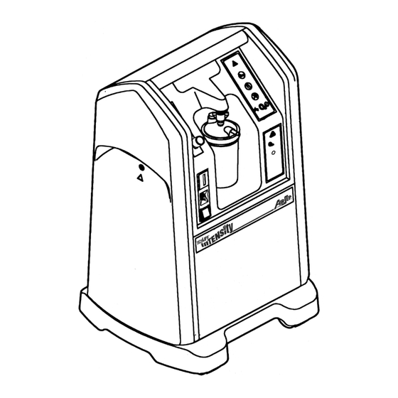
Page 15: Components
5.0 Main Components 5.1 Components The design of the AirSep NewLife Intensity 10 Oxygen Concentrator allows for easy access and removal of most components. This allows you to perform repair and replacement of parts with minimal time and effort. To prevent accidental electrical shock or burn, be sure to set the unit’s power switch to the “0”... -
Page 16: Compressor
Since this drop in oxygen production occurs over a long period of time, preventative maintenance on the compressor is not required. You can continue a patient’s therapy on the NewLife Intensity 10 unit as long as that unit’s oxygen concentration level at the prescribed liter flow rate is within AirSep’s specifications. -
Page 17: Capacitor Replacement
5.4 Solenoid Valves The NewLife Intensity 10 uses five two-way solenoid valves: two feed, two waste, and one equalization. Each valve has an open (energized) and closed (de-energized) position. As the NewLife Intensity 10 operates, two or three valves are always energized. -
Page 18: Sieve Beds
7. Reconnect the back and side panels. 5.5 Sieve Beds The NewLife Intensity 10 unit utilizes two sieve beds, each containing molecular sieve. The unique property of molecular sieve enables it to physically attract nitrogen when air passes through this material, thus producing highly concentrated oxygen. -
Page 19: Cabinet Fan
(including the compressor) and exits out the bottom of the unit. The cabinet fan for NewLife Intensity 10 is located in the back of the unit. Refer to the troubleshooting chart in Section 6.0 of this manual for instances where replacement of the fan may be required. -
Page 20: Circuit Board Replacement
A green light that fails to illuminate indicates a disconnected or faulty solenoid coil or an electrical malfunction in that valve circuit. The two vertical red lights indicate high and low pressure. Consult the troubleshooting chart in Section 6.0 to determine when to replace the printed circuit board. -
Page 21: Product Regulator Check And Setting
Disconnect the humidifier bottle, if used, and the tubing from oxygen outlet. Remove the side panels and back panel. Connect unit to power. Install outlet pressure test kit (TU131-2) to the outlet of the NewLife Intensity 10. Set the unit’s /0 power switch to the “... -
Page 22: Product Regulator Cleaning Or
5.9.2 Product Regulator Cleaning or Rebuilding Clean or rebuild the product regulator if the regulator cannot be adjusted for lockout. 1. Set the unit’s /0 switch to the “0” position and disconnect the power cord. 2. Remove the right side panels and back panels. 3. -
Page 23: Buzzer Replacement
/0 Power Switch Installation Follow the removal procedure for the /0 power switch in reverse order to install a new power switch. 1. Be sure to reinstall the new switch properly with the orientation of the “0” on the switch located on the bottom when finished. 2. -
Page 24: Oxygen Monitor Circuit Board Replacement
3. Open the plastic twist clamps. 4. Cut the tie-wraps (located near the power cord push-on connectors). 5. Disconnect the white power cord lead from the /0 switch lead. 6. Disconnect the black power cord lead from the top terminal on the circuit breaker. - Page 25 6.0 Troubleshooting 6.1 Operating Pressure Test Testing the operating pressure is a useful diagnostic tool when a concentrator produces low oxygen concentration and requires servicing. Units functioning normally do not require operating pressure tests. Use the following procedure to test the operating pressure of the unit: Set the unit’s /0 power switch to the “0”...
- Page 26 6.2 General Troubleshooting Before reviewing the troubleshooting chart, the following steps may be useful to isolate any malfunctions: Turn on the concentrator. If the unit does not turn on, refer to the troubleshooting chart. Verify the outlet pressure is 20 psig (138 kPa). If the outlet pressure is not at 20 psig (138 kPa), the product regulator needs to be reset.
- Page 27 6.3 Troubleshooting Chart Problem Probable Cause Solution Unit does not run. No power to unit from electrical outlet. Check/restore power to outlet. Constant audio alarm with Unit circuit breaker tripped/faulty. Reset or replace circuit breaker. I/0 power switch in “I” position. Faulty electrical connections.
- Page 28 Problem Probable Cause Solution Compressor runs with intermittent Restriction in exhaust muffler. Replace or clean muffler. high pressure alarm and low Repair or replace solenoid valve. Faulty solenoid valve. oxygen concentration. Replace circuit board. Faulty circuit board. Replace sieve beds. Contaminated sieve beds.
- Page 29 Problem Probable Cause Solution Cabinet fan does not turn. Faulty electrical connections. Check electrical connections. Faulty cabinet fan. Replace cabinet fan. Limited or low flow Restriction in humidifier/tubing. Replace humidifier or tubing. Product regulator set too low. Adjust regulator setting. Leak.
- Page 30 Tool Kit and Pressure Test Gauge The tools needed for you to properly service the NewLife Intensity 10 unit are listed below: Multi-adjustable pliers, wire cutters, needle-nose pliers, slotted-head screwdriver, Phillips- head screwdriver, ratchet, adjustable wrench, 1-inch deep well socket, 9/16-inch socket, 2- inch extension, 7/16-inch combination wrench, 9/16-inch combination wrench, and 5/8- inch combination wrench.
- Page 31 APPENDIX • Exploded drawings Wiring Diagram – Intensity 10 120V Wiring Diagram – Intensity 10 220/240V Control Panel Assembly Main Structure Assembly Base and Cabinet Components Product Tank/Regulator Assembly Valve Block Assembly Compressor Assembly Sieve Bed Assembly...
- Page 32 WIRING DIAGRAM INTENSITY 10 120V MN134-1 rev B 02/14...
- Page 33 WIRING DIAGRAM INTENSITY 10 220/240V MN134-1 rev B 02/14...
- Page 34 PART PART ITEM DESCRIPTION ITEM DESCRIPTION NUMBER NUMBER BK016-1 BRACKET, FLOWMETER, DUAL FA002-1 FASTENER, TIE WRAP MOUNT CA003-1 CABINET, CONTROL PANEL FM056-1 FLOWMETER CB068-9 CIRCUIT BOARD, 120V HM009-2 HOUR METER CB107-1 CIRCUIT BOARD, 220V MO002-1 MOUNT, CIRCUIT BOARD CR001-1 CIRCUIT BREAKER, 120V SW114-1 SWITCH, ON/OFF CR001-6...
- Page 35 PART PART ITEM DESCRIPTION ITEM DESCRIPTION NUMBER NUMBER BT001-2 BATTERY, HOLDER SC002-1 SCREW, TEMP SWITCH BT002-1 BATTERY SC001-2 SCREW, TERMINAL BLOCK CA214-1 CABINET, SUPERSTRUCTURE SC002-6 SCREW, FAN FA002-1 FASTENER, TIE-WRAP MOUNT SC003-1 SCREW, BUZZER FA003-1 FASTENER, WIRE HARNESS SC004-1 SCREW, BATTERY HOLDER FN022-1 FAN, 120V SW002-3...
- Page 36 PART PART ITEM DESCRIPTION ITEM DESCRIPTION NUMBER NUMBER BE186-1R BEDS CD011-2 CORD, POWER, US-STYLE CA034-1 CABINET, BACK PANEL CD011-4 CORD, POWER, EUROPEAN –STYLE CA036-4 CABINET, SIDE PANEL CS001-1 CASTER CA201-1 CABINET, ROLLER BASE FI002-1 FILTER, FOAM CA254-1 CABINET, FRONT PANEL BASE AND CABINET COMPONENTS MN134-1 rev B 02/14...
- Page 37 PART ITEM DESCRIPTION NUMBER RG088-1 REGULATOR (ONLY) TA132-1 TANK, MIXING, ASSY PRODUCT TANK/REGULATOR ASSEMBLY MN134-1 rev B 02/14...
- Page 38 PART PART ITEM DESCRIPTION ITEM DESCRIPTION NUMBER NUMBER VA290-3 VALVE, BLOCK (ONLY) VA117-1 VALVE, COIL, 220V VA034-1 VALVE, FEED/WASTE REBUILT KIT VA001-1 VALVE, SOLENOID, 120V VA054-1 VALVE, COIL, 120V VA001-2 VALVE, SOLENOID, 220V VALVE BLOCK ASSEMBLY ITEM PART DESCRIPTION ITEM PART DESCRIPTION MN134-1 rev B...
- Page 39 NUMBER NUMBER CL007-1 CLAMP, HEAT EXCHANGER F0104-1 FITTING, ELBOW, HEAT EXCHANGER CO306-1R COMPRESSOR, ASSY, 120V HX002-2 HEAT EXCHANGER CO306-2R COMPRESSOR, ASSY, 220V KI070-1 KIT, SPRING MOUNT F0045-2 FITTING, ELBOW, INTAKE SC013-2 SCREW, CLAMP F0627-1 FITTING, ADAPTER, INTAKE WA002-14 WASHER, CLAMP COMPRESSOR ASSEMBLY ITEM PART...
- Page 40 NUMBER NUMBER BE002-4 BED, TUBE F0001-2 FITTING, ELBOW, TOP CAP BE005-2 BEDS, LEFT CAP ASSY, TOP F0105-7 FITTING, ADAPTER, BOTTOM CAP BE005-3 BEDS, RIGHT CAP ASSY, TOP F0134-1 FITTING, COMPRESSION NUT BE006-1 BEDS, CAP ASSY, BOTTOM GS017-1 GASKET BE011-4 BEDS, RODS NU001-1 NUT, BOTTOM CAP BE058-1...
Need help?
Do you have a question about the Intensity 10 and is the answer not in the manual?
Questions and answers
Ako stíšiť zvuk motora
To reduce motor noise on the NewLife Intensity 10, check the condition of the compressor’s cup seals and bearings. If they are worn and causing increased noise, the compressor may need service or replacement.
This answer is automatically generated