Table of Contents
Advertisement
This manual is applicable to:
Record the model number and serial number of your planter along with date purchased:
Monitor Serial Number _______________________________________________
Measured Pulses Per Mile/Km (Radar Distance Sensor) ____________________
Measured Pulses Per Mile/ Km (Magnetic Distance Sensor) _________________
SERIAL NUMBER
The serial number plate is located on the planter frame as shown below. The serial number provides important information
about your planter and is needed to obtain correct replacement parts. Always provide model number and serial number
to your Kinze Dealer when ordering parts or when contacting Kinze Manufacturing, Inc.
Kinze
MODEL 4900
FRONT FOLD PLANTER
OPERATOR MANUAL
M0247-01
Model 4900 Forward Folding Planters for Production 2013 and on
Model Number ___________________________________
Serial Number ___________________________________
Date Purchased __________________________________
Serial Number Plate Location
and the Kinze
logo are registered trademarks of Kinze Manufacturing, Inc.
®
®
Vacuum Meter, Electric Drive, and Flip Axle have patents pending.
Rev. 10/17
4900
Advertisement
Chapters
Table of Contents

Related Manuals for Kinze 4900


Summary of Contents for Kinze 4900
- Page 1 The serial number plate is located on the planter frame as shown below. The serial number provides important information about your planter and is needed to obtain correct replacement parts. Always provide model number and serial number to your Kinze Dealer when ordering parts or when contacting Kinze Manufacturing, Inc. Serial Number Plate Location...
- Page 2 This page intentionally left blank.
- Page 3 Predelivery/Delivery Checklist M0247-01 Model 4900 TO THE DEALER Predelivery service includes assembly, lubrication, adjustment and test. This service helps ensure planter is delivered to retail customer/end user ready for field use. PREDELIVERY CHECKLIST Use the following checklist after planter is completely assembled. Check off each item as it is found satisfactory or after proper adjustment is made.
- Page 4 Predelivery/Delivery Checklist Model 4900 M0247-01 DELIVERY CHECKLIST Use the following checklist at time planter is delivered as a reminder of very important information which should be conveyed to retail customer/end user. Check off each item as it is fully explained.
-
Page 5: Table Of Contents
Table of Contents M0247-01 Model 4900 OVERVIEW Monitor Seed Levels ......2-64 Master Module ....... . . 2-65 To The Owner . - Page 6 Model 4900 M0247-01 RATE CHARTS ......5-1 Wiring Harness Schematic Advanced ISOBUS..6-36 Electrical Wiring Diagram - Advanced ISOBUS .
-
Page 7: To The Owner
M0247-01 Model 4900 Kinze Manufacturing, Inc. thanks you for your patronage. We appreciate your confidence in Kinze farm machinery. Your Kinze planter has been carefully designed to provide dependable operation in return for your investment. This manual has been prepared to aid you in the operation and maintenance of the planter. It should be considered a permanent part of the machine and remain with the machine when you sell it. - Page 8 NOTE: Some photos in this manual may have been taken of prototype machines. Production machines may vary in appearance. NOTE: Some photos and illustrations in this manual show optional attachments installed. Contact your Kinze Dealer for purchase of optional attachments.
-
Page 9: Warranty
Model 4900 WARRANTY The Kinze Limited Warranty for your new machine is stated on the retail purchaser’s copy of the Warranty And Delivery Receipt form. Additional copies of the Limited Warranty can be obtained through your Kinze Dealer. Warranty, within the warranty period, is provided as part of Kinze’s support program for registered Kinze products which have been operated and maintained as described in this manual. - Page 10 Model 4900 M0247-01 Information used in these instructions was current at time of printing. However, due to Kinze’s ongoing product improvement, production changes may cause your machine to appear slightly different in detail. Kinze Manufacturing, Inc. reserves the right to change specifications or design without notice and without incurring obligation to install the same on machines previously manufactured.
-
Page 11: Specifications
Specifications M0247-01 Model 4900 Specifications - Electric Drive Specification Conventional Hoppers Bulk Fill Number of Rows Row Spacing 30" 30" 30" 30" 30" 30" Weight Empty 14,300 - 16,370 lb 18,930 - 20,180 lb 28,000 - 30,875 lb 14,300 - 16,370 lb... -
Page 12: Specifications
Specifications Model 4900 M0247-01 Specifications - Ground or Hydraulic Drive Specification Conventional Hoppers Bulk Fill Number of Rows Row Spacing 30" 30" 30" 30" 30" 30" Weight Empty 14,300 - 16,370 lb 18,930 - 20,180 lb 28,000 - 30,875 lb... - Page 13 Power Beyond requires an external load signal. Kinze suggests that if Power Beyond must be used, only the bulk fill circuit be connected using all three connections (Pressure, Return, Load Sense). Consult your tractor manufacturer to ensure proper connection, hydraulic flow, pressure and heat dissipation are met.
- Page 14 All 4900 planters require an external case drain hose. • All SCVs should be set to max flow at all times with the exception of the bulk fill circuit on mechanical 4900. • Tractor RPMs not recommended below 1750 RPMs.
-
Page 15: General Safety Rules
If you install such drives, follow all appropriate Model 4900 planter consists of 85% recyclable metals, 10% safety standards and practices to protect you and others recyclable plastic and rubber, and 5% waste. -
Page 16: Safety Precautions
Safety Precautions Model 4900 M0247-01 Following are some common hazard warnings associated with this equipment. Pay close attention to all safety, operating, and maintenance information in this manual and decals applied to your equipment. Contacting or coming close to power... - Page 17 M0247-01 Model 4900 SAFETY SIGNS AND DECALS All safety/warning lights, reflective WARNING decals, and SMV sign must be in place and visible before transporting machine on public roads or death, serious injury, and damage to property and equipment may result. Check federal, state/ provincial, and local regulations before transporting equipment on public roads.
- Page 18 This page intentionally left blank.
-
Page 19: Machine Operation
Machine Operation M0247-01 Model 4900 ROW MARKER SAFETY LOCKUP Row marker can lower at any time and WARNING could cause death or serious injury. Stay away from row markers! Install safety lockup device when not in use. Row Marker Safety Lockup Installed Row Marker Safety Lockup Stored Always install row marker lockups when working on, storing, or transporting planter. -
Page 20: Transport Axle Cylinder Safety Lockup
Machine Operation Model 4900 M0247-01 TRANSPORT AXLE CYLINDER SAFETY LOCKUP Transport axle can lower from transport WARNING position without the use of any controller, causing death, serious injury, or damage to property and equipment. Do not operate any hydraulic function while transporting the planter. -
Page 21: Drawbar Hitch Lockup (Option)
Machine Operation M0247-01 Model 4900 Planter hitch may raise uncontrollably WARNING during folding/unfolding and can cause death, serious injury, or damage property and equipment. DO NOT fold or unfold planter without planter attached to a tractor. DO NOT unhitch planter from... -
Page 22: 2-Point Hitch Option
Machine Operation Model 4900 M0247-01 2-POINT HITCH OPTION Jacks in Maintenance Position For transporting, store jacks on both sides of hitch. Secure in place with spring pin. Rev. 10/17... -
Page 23: Initial Planter Preparation
Machine Operation M0247-01 Model 4900 Improperly operating or working on WARNING this equipment could result in death or serious injury. Read and follow all instructions in Operator Manual before operating or working on this equipment. INITIAL PLANTER PREPARATION Following information is general in nature to aid in preparation of tractor and planter for use, and to provide general operating procedures. - Page 24 Machine Operation Model 4900 M0247-01 Row marker Transport Wing Tire locations (L.H. shown) 1. Torque transport wheel ¾"- 16 lug nuts to 200 ft-lb (244 N-m). 2. Inflate tires to the following specifications: • 2014 Production: Wing - 12R and 16R: 7.5” x 20” - 40 psi (275.7 kPa), 24R: 41” x 11” - 60 psi (413.6 kPa) •...
-
Page 25: Tractor Requirements
Machine Operation M0247-01 Model 4900 TRACTOR REQUIREMENTS Loss of control of equipment during WARNING transport can result in death, serious injury, or damage to property and equipment. Tractor gross weight must be greater than planter gross weight with attachments and options. -
Page 26: Tractor Preparation And Hookup
Machine Operation Model 4900 M0247-01 Vacuum meter equipped planters require a 1¾"-20 spline 1000 RPM PTO to operate PTO-driven two section hydraulic pump capable of supplying 15 gpm (56.8 Lpm) to two hydraulic motors/vacuum fans. NOTE: A tractor model-specific mount kit is required for the PTO-mounted pump. - Page 27 Machine Operation M0247-01 Model 4900 Pressurized hydraulic fluid can penetrate WARNING body tissue and result in death, serious infection, or other injuries. Fluid injected under skin must be IMMEDIATELY removed by a surgeon familiar with this type of injury. Make sure connections...
- Page 28 Machine Operation Model 4900 M0247-01 Clean and grease PTO shaft coupling NOTICE with high-pressure industrial coupling grease (Chevron coupling grease or ® equivalent) meeting AGMA CG-1 and CG-2 Standards each time driveshaft is installed or premature wear and equipment failure can occur.
-
Page 29: Cylinder Information
Machine Operation M0247-01 Model 4900 CYLINDER INFORMATION Drawbar Hitch Drawbar Hitch Row Marker Cylinder, Row Marker Cylinder, Fold Cylinder, Cylinder, Cylinder, 12 Row 16 and 24 Row 12 and 16 Row 12 and 16 Row 24 Row Double acting Double acting... - Page 30 Machine Operation Model 4900 M0247-01 CYLINDER INFORMATION Fold Cylinder, Fold Cylinder, Fold Cylinder, Fold Cylinder, Fold Cylinder, 24 Row 24 Row 24 Row 24 Row 12 and 16 Row (2014 Production) (2014 Production) (2015 Production) (2015 Production) Double acting Double acting...
- Page 31 Machine Operation M0247-01 Model 4900 CYLINDER INFORMATION Wing Cylinder, Wing Cylinder, Master Cylinder Wing Cylinder, Wing Cylinder, 24 Row 24 Row Center, 12 Row 16 Row (Non-Flip Axle) (Flip Axle) 12 Row Double acting Double acting Double acting Double acting...
- Page 32 Machine Operation Model 4900 M0247-01 CYLINDER INFORMATION Master Cylinder Master Cylinder Wing Cylinder Wing Down Pressure Wind Down Pressure Center, Center, 24 Row Center, 24 Row Cylinder, Cylinder, 16 Row (Non-Flip Axle) (Flip Axle) 12 and 16 Row 24 Row...
-
Page 33: Hydraulic Hose Information
Machine Operation M0247-01 Model 4900 HYDRAULIC HOSE INFORMATION Part Number A1010 A1026 A1027 A1029 A1030 A1041 Hose Assembly Hose Assembly Hose Assembly Hose Assembly Hose Assembly Hose Assembly Description ⅜" X 120" ⅜" X 152" 3∕8" X 182" 3∕8" X 190"... - Page 34 Machine Operation Model 4900 M0247-01 HYDRAULIC HOSE INFORMATION Part Number A12063 A15013 A15019 A15020 A15024 A15025 Hose Assembly Hose Assembly Hose Assembly Hose Assembly Hose Assembly Hose Assembly Description ⅜" X 141" ⅜" X 32" 3∕8" X 128" 3∕8" X 38"...
- Page 35 Machine Operation M0247-01 Model 4900 HYDRAULIC HOSE INFORMATION Part Number A15035-218 A15035-252 A15035-361 A15035-368 A15039 A15042 Hose Assembly Hose Assembly Hose Assembly Hose Assembly Hose Assembly Hose Assembly Description ⅜" X 218" ⅜" X 252" 3∕8" X 361" 3∕8" X 368"...
- Page 36 Machine Operation Model 4900 M0247-01 HYDRAULIC HOSE INFORMATION Part Number A3199 A3118 A3136 A3139 A3140 A3156 Hose Assembly Hose Assembly Hose Assembly Hose Assembly Hose Assembly Hose Assembly Description ⅜" X 132" ⅜" X 80" 3∕8" X 100" 3∕8" X 254"...
- Page 37 Machine Operation M0247-01 Model 4900 HYDRAULIC HOSE INFORMATION Part Number A15032-324 A3114 A12783 A12784 A12785 A12786 Hose Assembly Hose Assembly Hose Assembly Hose Assembly Hose Assembly Hose Assembly Description ⅜" X 324" ⅜" X 156" ½" x 41" ½" x 48"...
- Page 38 Machine Operation Model 4900 M0247-01 HYDRAULIC HOSE INFORMATION Part Number A11481-228 A11481-329 A11482-224 A11482-258 A11482-361 A11482-368 Hose Assembly Hose Assembly Hose Assembly Hose Assembly Hose Assembly Hose Assembly Description 5∕8" X 227" 5∕8" X 329" 5∕8" X 224" 5∕8" X 258"...
- Page 39 Machine Operation M0247-01 Model 4900 HYDRAULIC HOSE INFORMATION Part Number A18627 A18625 A18629-174 A18629-180 A18629-204 A18629-228 Hose Assembly Hose Assembly Hose Assembly Hose Assembly Hose Assembly Hose Assembly Description ½" x 180" ½" x 162" ½" x 174" ½" x 180"...
- Page 40 Machine Operation Model 4900 M0247-01 HYDRAULIC HOSE INFORMATION Part Number A18635 A18636 A18638 A18639 A18640 A18641 Hose Assembly Hose Assembly Hose Assembly Hose Assembly Hose Assembly Hose Assembly Description ½" x 86" ½" x 109" ½" x 160" ½" x 24"...
- Page 41 Machine Operation M0247-01 Model 4900 HYDRAULIC HOSE INFORMATION Part Number A7658 A7668 A12789 A8248 A8264 A8280 Hose Assembly Hose Assembly Hose Assembly Hose Assembly Hose Assembly Hose Assembly Description ¼" x 58" ¼" x 76" ½" x 98" ½" x 168"...
- Page 42 Machine Operation Model 4900 M0247-01 HYDRAULIC HOSE INFORMATION Part Number A12793 A12795 A12799 A1420 A1467 Hose Assembly Hose Assembly Hose Assembly Hose Assembly Hose Assembly Description ½" x 131" ½" x 123" ½" x 31" ½" x 48" ½" x 120"...
-
Page 43: Transporting Planter
Machine Operation M0247-01 Model 4900 TRANSPORTING PLANTER Uncontrolled movement of equipment WARNING can cause loss of control and could result in death, serious injury, or damage to property and equipment. Install all safety pins before transporting equipment. Uncontrolled machine movement can... -
Page 44: Level Planter
If planter center is higher or lower than wings after rephasing, contact your Kinze Dealer for valve adjustment or maintenance. -
Page 45: Jump Start Sensor
1/8" of the pick-up disc. The planter speed sensor also needs to be calibrated properly and have the speed source set to automatic. Refer to Kinze ISOBUS Operator’s Manual (M0246) for calibration instructions. Pick-up disc... -
Page 46: Transport To Field Sequence Using Isobus
Machine Operation Model 4900 M0247-01 TRANSPORT TO FIELD SEQUENCE USING ISOBUS (If applicable, refer to “Transport to Field Sequence Using Control Box” on page 2-33 “Transport to Field Sequence Using Advanced ISOBUS Control Box” on page 2-38) Position planter in a relatively flat open area without furrows, etc. - Page 47 Machine Operation M0247-01 Model 4900 DO NOT fold or unfold planter without NOTICE planter attached to a tractor. DO NOT unhitch planter from tractor unless fully folded for transport or fully unfolded with planting units lowered to ground. Install locking pin Remove and store locking pin on drawbar hitch.
- Page 48 Machine Operation Model 4900 M0247-01 2. Operate the proper hydraulic tractor control and press and hold the WING WHEEL LOWER button on your ISOBUS monitor to lower wing wheels into field turnaround position. 3. Operate the proper hydraulic tractor control and press...
- Page 49 Machine Operation M0247-01 Model 4900 For planters equipped with drawbar hitch, operate proper hydraulic tractor control and press and hold the LOWER HITCH button on your ISOBUS monitor to unhook wings. For planters equipped with 2-point hitch, operate proper hydraulic tractor control to lower drawbar to unhook wings.
- Page 50 Machine Operation Model 4900 M0247-01 Unfolding planter without using tractor NOTICE to assist may cause equipment damage especially in soft conditions or when loaded with seed or fertilizer. Use tractor to reduce stress on frame, drive, and transport components. 5. Operate the proper hydraulic tractor control and press and hold the UNFOLD button on your ISOBUS monitor to move wings out, away from tractor.
-
Page 51: Transport To Field Sequence Using Control Box
Machine Operation M0247-01 Model 4900 TRANSPORT TO FIELD SEQUENCE USING CONTROL BOX (If applicable, refer to “Transport to Field Sequence Using Advanced ISOBUS Control Box” on page 2-38) Position planter in a relatively flat open area without furrows, etc. SUMMARIZED TRANSPORT TO FIELD SEQUENCE... - Page 52 Machine Operation Model 4900 M0247-01 DO NOT fold or unfold planter without NOTICE planter attached to a tractor. DO NOT unhitch planter from tractor unless fully folded for transport or fully unfolded with planting units lowered to ground. Install locking pin Remove and store locking pin on drawbar hitch.
- Page 53 Machine Operation M0247-01 Model 4900 2. Place FUNCTION switch on control box in fold MARKERS FUNCTION position. LEFT RIGHT PLANT FOLD 3. Operate the proper hydraulic tractor control and press and hold the WING WHEEL switch down to lower wing...
- Page 54 Machine Operation Model 4900 M0247-01 For planters equipped with drawbar hitch, MARKERS FUNCTION operate proper hydraulic tractor control and press and hold the HITCH button down to LEFT RIGHT PLANT FOLD raise drawbar to unhook wings. VACUUM WORK For planters equipped with 2-point hitch,...
- Page 55 Machine Operation M0247-01 Model 4900 Unfolding planter without using tractor NOTICE to assist may cause equipment damage especially in soft conditions or when loaded with seed or fertilizer. Use tractor to reduce stress on frame, drive, and transport components. 6. Operate the proper hydraulic tractor control and...
-
Page 56: Transport To Field Sequence Using Advanced Isobus Control Box
Machine Operation Model 4900 M0247-01 TRANSPORT TO FIELD SEQUENCE USING ADVANCED ISOBUS CONTROL BOX Position planter in a relatively flat open area without furrows, etc. SUMMARIZED TRANSPORT TO FIELD SEQUENCE USING CONTROL BOX Tractor must be in neutral and allowed... - Page 57 Machine Operation M0247-01 Model 4900 DO NOT fold or unfold planter without NOTICE planter attached to a tractor. DO NOT unhitch planter from tractor unless fully folded for transport or fully unfolded with planting units lowered to ground. Install locking pin Remove and store locking pin on drawbar hitch.
- Page 58 Machine Operation Model 4900 M0247-01 2. Place FUNCTION switch on control box in fold position. MARKERS FUNCTION LEFT RIGHT PLANT FOLD 3. Operate the proper hydraulic tractor control and press and hold the WING WHEEL switch down to lower wing...
- Page 59 Machine Operation M0247-01 Model 4900 Unfolding planter without using tractor NOTICE to assist may cause equipment damage especially in soft conditions or when loaded with seed or fertilizer. Use tractor to reduce stress on frame, drive, and transport components. 6. Operate the proper hydraulic tractor control and press the FOLD switch up to move wings out, away from tractor.
-
Page 60: Field To Transport Sequence Using Isobus
Machine Operation Model 4900 M0247-01 FIELD TO TRANSPORT SEQUENCE USING ISOBUS (If applicable, refer to “Field to Transport Sequence Using Control Box” on page 2-47 “Field to Transport Sequence Using Advanced ISOBUS Control Box” on page 2-51) Position planter in a relatively flat open area without furrows, etc. - Page 61 Machine Operation M0247-01 Model 4900 DO NOT fold or unfold planter without NOTICE planter attached to a tractor. DO NOT unhitch planter from tractor unless fully folded for transport or fully unfolded with planting units lowered to ground. If equipped with row markers, remove lockups from storage and install on marker cylinder rods.
- Page 62 Machine Operation Model 4900 M0247-01 Folding planter without using tractor to NOTICE assist may cause equipment damage especially in soft conditions or when loaded with seed or fertilizer. Use tractor to reduce stress on frame, drive, and transport components. 4. Operate the proper hydraulic tractor control and press and hold the FOLD button on your ISOBUS monitor until 2 hooks are over the top of the inner hitch.
- Page 63 Machine Operation M0247-01 Model 4900 6. Operate the proper hydraulic tractor control and press and hold the ROTATE AXLE button on your ISOBUS monitor to raise transport axle to either transport height, or if equipped with flip axle, to the rest position as shown below.
- Page 64 Machine Operation Model 4900 M0247-01 8. Install locking pin on drawbar. Install locking pin here for transport 9. Install lockups. Locking pin storage Locking Pin for Drawbar Hitch 2-46 Rev. 10/17...
-
Page 65: Field To Transport Sequence Using Control Box
Machine Operation M0247-01 Model 4900 FIELD TO TRANSPORT SEQUENCE USING CONTROL BOX (If applicable, refer to “Field to Transport Sequence Using Advanced ISOBUS Control Box” on page 2-51) Position planter in a relatively flat open area without furrows, etc. SUMMARIZED FIELD TO TRANSPORT SEQUENCE... - Page 66 Machine Operation Model 4900 M0247-01 DO NOT fold or unfold planter without NOTICE planter attached to a tractor. DO NOT unhitch planter from tractor unless fully folded for transport or fully unfolded with planting units lowered to ground. If equipped with row markers, remove lockups from storage and install on marker cylinder rods.
- Page 67 Machine Operation M0247-01 Model 4900 Unfolding planter without using tractor NOTICE to assist may cause equipment damage especially in soft conditions or when loaded with seed or fertilizer. Use tractor to reduce stress on frame, drive, and transport components. MARKERS...
- Page 68 Machine Operation Model 4900 M0247-01 7. Operate the proper hydraulic tractor control and press the AXLE switch up to raise transport axle MARKERS FUNCTION to either transport height, or if equipped with flip axle, to the rest position as shown below.
-
Page 69: Field To Transport Sequence Using Advanced Isobus Control Box
Machine Operation M0247-01 Model 4900 FIELD TO TRANSPORT SEQUENCE USING ADVANCED ISOBUS CONTROL BOX Position planter in a relatively flat open area without furrows, etc. SUMMARIZED FIELD TO TRANSPORT SEQUENCE USING CONTROL BOX NOTICE Tractor must be in neutral and allowed... - Page 70 Machine Operation Model 4900 M0247-01 DO NOT fold or unfold planter without NOTICE planter attached to a tractor. DO NOT unhitch planter from tractor unless fully folded for transport or fully unfolded with planting units lowered to ground. If equipped with row markers, remove lockups from storage and install on marker cylinder rods.
- Page 71 Machine Operation M0247-01 Model 4900 Folding planter without using tractor to NOTICE assist may cause equipment damage especially in soft conditions or when loaded with seed or fertilizer. Use tractor to reduce stress on frame, drive, and transport components. 5. Operate the proper hydraulic tractor control and...
- Page 72 Machine Operation Model 4900 M0247-01 7. Operate the proper hydraulic tractor control and press the AXLE switch up to raise transport axle MARKERS FUNCTION to either transport height, or if equipped with flip LEFT RIGHT PLANT FOLD axle, to the rest position as shown below.
-
Page 73: Row Marker Operation Using Isobus
Machine Operation M0247-01 Model 4900 ROW MARKER OPERATION USING ISOBUS (Row marker operation using control box, proceed to next page) Contacting or coming close to power DANGER lines or other high energy sources will cause death or serious injury. Keep away from power lines or high energy sources at all times. -
Page 74: Row Marker Operation Using Control Box
Machine Operation Model 4900 M0247-01 ROW MARKER OPERATION USING CONTROL BOX Contacting or coming close to power DANGER lines or other high energy sources will cause death or serious injury. Keep away from power lines or high energy sources at all times. -
Page 75: Row Marker Speed Adjustment
Machine Operation M0247-01 Model 4900 ROW MARKER SPEED ADJUSTMENT Excessive row marker travel speed NOTICE can damage row markers. Adjust flow controls before row markers are first used. Marker hydraulic system includes two flow control valves. One flow control valve sets lowering speed and one sets raising speed of both markers. -
Page 76: Row Marker Cable Adjustment
Machine Operation Model 4900 M0247-01 ROW MARKER CABLE ADJUSTMENT Uncontrolled marker movement can WARNING cause death or serious injury. Set marker switch to OFF and shut off tractor prior to adjustment. NOTE: Operate two-fold or three-fold row markers with the tractor's hydraulic valve in float position. -
Page 77: Row Marker Length And Disc Blade Adjustment
5. Loosen hardware and move assembly as required. 6. Tighten bolts to specified torque. 7. Do a field test to ensure markers are properly adjusted. NOTE: A notched marker blade is available from Kinze through your Kinze Dealer for use in more severe no till conditions. 2-59... -
Page 78: Vacuum Meter System
M0247-01 VACUUM METER SYSTEM Kinze vacuum meter seed metering system includes seed meters, seed discs, and an air system consisting of a hydraulic driven vacuum fan which draws air through manifolds, hoses, and seed meters on each row unit. Moving fan blades can cause amputation WARNING or severe injury. -
Page 79: Bulk Fill System
Machine Operation M0247-01 Model 4900 BULK FILL SYSTEM Do not remove lid during machine WARNING operation. Contents are pressurized and could result in death, serious injuries or equipment damage. Review operator manual for proper filling procedure. Seed flying out of disconnected delivery CAUTION tube at high velocity can cause injury. - Page 80 Machine Operation Model 4900 M0247-01 1. Before filling hoppers, refer to “Row Unit Operation” on page 3-1 for additives information. Fill hoppers with seed, then twist lid clockwise to close. 2. Start bulk fill delivery system with tractor engine at idle.
-
Page 81: Bulk Fill Entrainer Access
Machine Operation M0247-01 Model 4900 BULK FILL ENTRAINER ACCESS Wing nut 1. Shut down bulk fill system. 2. Loosen wing nut and turn retainer holding shutoff door in its storage location. Rubber plug 3. Remove rubber plug closest to area in entrainer needing Retainer attention. -
Page 82: Bulk Fill Scale Package Option
Machine Operation Model 4900 M0247-01 BULK FILL SCALE PACKAGE OPTION High-pressure water can damage display. NOTICE Remove display before power washing planter. Remove and store display at end of NOTICE planting season. Damage from sun and weather exposure may result. -
Page 83: Master Module
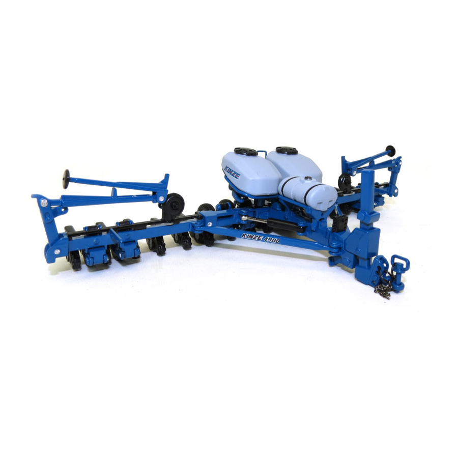
Virtual Terminal (VT). It also executes the manual and automatic rate control, and swath control commands. These functions are available with the Kinze ISOBUS product control package. Planter Master Module (PMM) (Bulk fill system shown) -
Page 84: Field Test
Machine Operation Model 4900 M0247-01 FIELD TEST Perform a field test with any change of field and/or planting conditions, seed size or planter adjustment to ensure proper seed placement and operation of row units. Check planter for front to rear and lateral level operation. See “Level Planter”... -
Page 85: Determining Pounds Per Acre
Machine Operation M0247-01 Model 4900 3. Measure 1∕1000 of an acre. See chart for correct distance for row width being planted. For example, planting 30" rows 1∕1000 of an acre is 17' 5". 1∕1000 Acre Seed Population Count Row Width/... -
Page 86: Field Check Granular Chemical Application
Machine Operation Model 4900 M0247-01 FIELD CHECK GRANULAR CHEMICAL APPLICATION Temperature, humidity, speed, ground conditions, flowability of different material, or meter obstructions can affect granular chemical rate of delivery. Agricultural chemicals can cause death WARNING or serious injury to persons, animals, and plants or seriously damage soil, equipment, or property. -
Page 87: Water Tank
Machine Operation M0247-01 Model 4900 WATER TANK The water tank is to only be filled with clean water or preferably potable water (water meeting local standards for drinking). The tank holds 4 gallons (15 L) of water. Be sure to check for regulations pertaining to this use. - Page 88 This page intentionally left blank.
-
Page 89: Row Unit Operation
Row Unit Operation M0247-01 Model 4900 PLANTING DEPTH Planting Planting depth is maintained by adjustable row unit gauge depth wheels. Depth adjustment range is approximately ½" to 3½" adjustment (1.2 to 8.8 cm). handle Raise planter to remove weight from wheels. -
Page 90: Covering Discs/Single Press Wheel Adjustment
Row Unit Operation Model 4900 M0247-01 COVERING DISCS/SINGLE PRESS WHEEL ADJUSTMENT Adjusting bolt ½" Locking nut Press Wheel Down Force Adjustment Check operation of covering discs/single press wheels after adjusting planting depth. Initial press wheel down force spring setting is 2½" between mounting arm tab and locking nut. Loosen ½" locking nut and turn adjusting bolt in to increase down force or out to decrease down force. -
Page 91: Seed Hoppers
Row Unit Operation M0247-01 Model 4900 SEED HOPPERS Seed hoppers have a capacity option of 1.9 or 3.0 bushels. NOTE: Planters with the insecticide option are required to use only the 1.9 bushel hoppers. Use clean seed and make certain there are no foreign objects inside when filling seed hopper. -
Page 92: Quick Adjustable Down Force Springs Option
Row Unit Operation Model 4900 M0247-01 QUICK ADJUSTABLE DOWN FORCE SPRINGS OPTION Standard and heavy duty quick adjustable down force springs are available in increase penetration in hard soil and keep row unit from bouncing in rough field conditions. Two springs per row, one on each side parallel arms, are used unless equipped with row unit mounted no till coulters. -
Page 93: Pneumatic Down Pressure
Packages include upper and lower air spring mounting castings for pull row units, 150 psi rated air springs, ⅜" O.D. nylon hoses, dual solenoid air valve and stainless steel, 160 psi, 2" liquid-filled gauge and planter wiring harness. NOTE: Assist springs are available through your Kinze dealer if additional down pressure is needed. TEMPERATURE SENSOR OPTION... -
Page 94: Field Operation
Row Unit Operation Model 4900 M0247-01 FIELD OPERATION NOTE: Adjust down pressure with planter lowered and row openers in ground for most accurate adjustment. Pressure can be adjusted using your ISOBUS monitor. Refer to the ISOBUS manual for more information. -
Page 95: Vacuum Settings
Row Unit Operation M0247-01 Model 4900 VACUUM SETTINGS Vacuum Seed Ejector Singulator Setting **Seed Disc Wheel Seed Size Zone Inches of Crop Disc Kit Part No. (Color) Cells Range Setting Water (kPa) Lubricant Corn Graphite* Talc* B0678 1 row 35-70 lbs/80k 18-20 ‡... -
Page 96: Brush-Type Seed Meter
Row Unit Operation Model 4900 M0247-01 BRUSH-TYPE SEED METER Upper Disc Color-Code Brush Seed Size Crop (Disc Part No.) Retainer Cells Range *Lubricant Soybean Black GD11122 2200 to 4000 Graphite (GA5794) seeds/lb. Talc (4480 to 8800 kg) Graphite Specialty Soybean... -
Page 97: Finger Pickup Seed Meter
Row Unit Operation M0247-01 Model 4900 Turn seed disc counterclockwise when installing on meter hub while tightening two wing nuts that retain disc. Seed disc should have slight resistance when rotated counterclockwise after wing nuts are tight. Brush-type seed meter attaches to seed hopper same as finger pickup seed meter. - Page 98 Row Unit Operation Model 4900 M0247-01 NOTE: See “Field Check Seed Population” on page 2-66 for more information. Always field check seed population to ensure planting rates are correct. NOTE: Singulator settings are marked from 0 - 3. NOTE: Mixing seed sizes and shapes affects meter performance. Use consistent seed size and shape.
- Page 99 Row Unit Operation M0247-01 Model 4900 Ejector NOTE: Damaged seed or seed containing foreign material will cause plugging of seed disc orifices and require more frequent seed meter cleanout to prevent underplanting. Wheel-Type Ejectors Wheel-type ejectors expel seed remants from seed disc orifices. These ejectors are disc specific and colored coded to match disc.
-
Page 100: Seed Meter Cleanout
Row Unit Operation Model 4900 M0247-01 SEED METER CLEANOUT NOTE: Use of damaged seed or seed containing foreign material will cause plugging of seed cell orifices and require more frequent seed meter cleanout to prevent underplanting. Thorough seed meter cleanout is important to maintain genetic purity. -
Page 101: Additives
Row Unit Operation M0247-01 Model 4900 ADDITIVES Lubricant Application Rate The use of graphite is recommended to promote seed flow, provide Graphite lubrication for the seed meter and to help dissipate static charge buildup. Among the available dry seed lubricants graphite is the most Conventional Hoppers 1 Tbs./Hopper Fill... -
Page 102: Bayer Fluency Agent
This product, as tested by Kinze, is compatible with Kinze’s bulk fill system and vacuum meters. Due to limited testing, wear life characteristics of meters and bulk fill systems that use Bayer Fluency Agent are not yet known. Please follow Bayer Fluency Agent instructions for rates and mixing directions. -
Page 103: Gfx Hydraulic Row Cleaners
Row Unit Operation M0247-01 Model 4900 GFX HYDRAULIC ROW CLEANERS Pressurized hydraulic fluid can penetrate WARNING body tissue and result in death, serious infection, or other injuries. Fluid injected under skin must be IMMEDIATELY removed by a surgeon familiar with this type of injury. -
Page 104: Coulter Mounted Residue Wheels
Row Unit Operation Model 4900 M0247-01 COULTER MOUNTED RESIDUE WHEELS Coulter mounted residue wheels are designed for use on row units. Weed guard NOTE: Opening in weed guard must face down. Coulter Mounted Residue Wheels Residue wheels attach to row unit mounted coulter with two cap screws and sleeves allowing unit to free-float. A 2-position spindle bolt mounting positions wheels interlocked or staggered. -
Page 105: Granular Chemical Hopper And Drive
Row Unit Operation M0247-01 Model 4900 GRANULAR CHEMICAL HOPPER AND DRIVE Agricultural chemicals can cause death WARNING or serious injury to persons, animals, and plants or seriously damage soil, equipment, or property. Read and follow all chemical and equipment manufacturers labels and instructions. - Page 106 This page intentionally blank.
-
Page 107: Fertilizer
Fertilizer M0247-01 Model 4900 SYSTEM OVERVIEW Fertilizer is controlled through the Virtual Terminal on your Advanced ISOBUS. You can increase or decrease fertilizer rate, turn fertilizer function on or off, and load a prescription. Refer to your Advanced ISOBUS manual for more information. - Page 108 Fertilizer Model 4900 M0247-01 Low level sensor 1 Solenoid (back of tank) Bleed-off Hose Filters Pressure Relief Valve Low level sensor 2 3-Way Valve Centrifugal Pump Underneath Fertilizer Tank Solenoid allows oil to go to centrifugal pump and turn. It is controlled from the Master Module on the planter.
- Page 109 Fertilizer M0247-01 Model 4900 Orifice Plate Shut-off Fertilizer Control Valve (Turn tab and remove fitting) Flow Meter Flow Sensor On Toolbar at Row Underneath Bulk Fill Tank Pressure Gauge Flow Meter measures fertilizer rate when operating in the field and is displayed in the tractor cab.
-
Page 110: Piston Pump
Fertilizer Model 4900 M0247-01 PISTON PUMP NOTE: Keep manuals shipped with piston pump and flow divider with this manual. Piston pump Adjusting delivery rate NOTE: Delivery rate chart in Rate Chart section of this manual provides approximate application rate only. -
Page 111: Notched Single Disc Openers
Fertilizer M0247-01 Model 4900 NOTCHED SINGLE DISC OPENERS Position 2 Position 3 (operating) (operating) Opener mount Position 1 8" - 9" spring length (stowed) (20 - 22 cm) Disc blade Depth adjustment cam Knife Lift point Notched single disc opener adjustments Never place fertilizer closer than 2"... -
Page 112: Gauge Wheel Depth Adjustment
Fertilizer Model 4900 M0247-01 GAUGE WHEEL DEPTH ADJUSTMENT Gauge Wheel Arm Liquid Drop Tube Depth Adjustment Cam Positions Depth Adjustment Cam Position Depth Cam and Handle 2" (5 cm) 2.4" (6 cm) 2.8" (7.1 cm) 3.2" (8.1 cm) 3.6" (9.1 cm) 4"... -
Page 113: Downforce Settings
Fertilizer M0247-01 Model 4900 DOWNFORCE SETTINGS Down Force Settings 9" (23 cm) 8.5" (21 cm) 8" (20 cm) Position 1 (Stowed) Position 2 - Operating Position 2 110 - 160 150 - 210 200 - 250 (Softer Soil Conditions) Main bolt... -
Page 114: Knife Adjustment
Fertilizer Model 4900 M0247-01 KNIFE ADJUSTMENT Compressed spring may fly out of this CAUTION assembly if attempting to disassemble and cause injury. Do not take apart this assembly. Disc blades are sharp and can cut causing serious injury. Wear gloves when working on or turning disc blades by hand. - Page 115 Fertilizer M0247-01 Model 4900 Check knife to disc blade clearance and adjust if necessary as described below. Knife must be adjusted such that the leading edge is tight to the disc blade to keep soil and residue from wedging between them. Knife pitch is also critical to performance. Knife to disc blade gap has been factory preset at ⅜", measured at top rear of knife.
-
Page 116: Liquid Fertilizer Attachment
Placing fertilizer too close to seeds NOTICE or in excessive amounts can cause germination or seedling damage. Check with your fertilizer dealer or manufacturer for correct amount and placement. Liquid fertilizer installed on 4900 bulk fill 4-10 Rev. 10/17... -
Page 117: Check Valves
Fertilizer M0247-01 Model 4900 CHECK VALVES Low rate check valves are provided for in-line installation between liquid fertilizer piston pump and openers or in-furrow to ensure equal distribution of product at low rates and siphon protection for field turns. Check valves eliminate the need for anti-siphon loops. - Page 118 This page left blank intentionally.
-
Page 119: Rate Charts
Rate Charts M0247-01 Model 4900 GENERAL PLANTING RATE INFORMATION These planting rate charts apply to KINZE Model 4900 planters. Sprocket combinations in these charts are NOTICE for average conditions. Changes in sprocket combinations may be required for desired planting population. ALWAYS MAKE FIELD CHECKS TO BE SURE YOU ARE PLANTING AT THE DESIRED RATE. - Page 120 Rate Charts Model 4900 M0247-01 PLANTING RATES FOR FINGER PICKUP SEED METER (28 TOOTH CONTACT DRIVE) APPROXIMATE SEEDS/ACRE FOR 30" ROW WIDTH Transmission Sprockets Recommended Average Seed Spacing In Inches 30"Rows Drive Driven Speed Range (MPH) 13,330 4 to 6 15.7...
- Page 121 Rate Charts M0247-01 Model 4900 PLANTING RATES FOR BRUSH-TYPE SEED METERS (28 TOOTH CONTACT DRIVE) APPROXIMATE SEEDS/ACRE FOR 30" ROW WIDTH 60 Cell Soybean Or High-Rate 48 Cell Specialty Soybean Or Transmission Average Average Speed Seed Seed Sprockets Range Milo/Grain Sorghum...
- Page 122 Rate Charts Model 4900 M0247-01 PLANTING RATE FOR BRUSH-TYPE SEED METERS (28 TOOTH CONTACT DRIVE) APPROXIMATE SEEDS/ACRE FOR 30" ROW WIDTH 36 Cell 30 Cell Milo/Grain Sorghum Or Transmission Average Average Speed Seed Seed Sprockets Range Acid-Delinted Large Cotton Acid-Delinted Cotton...
- Page 123 Rate Charts M0247-01 Model 4900 PLANTING RATES FOR BRUSH-TYPE SEED METERS (28 TOOTH CONTACT DRIVE) APPROXIMATE HILLS/ACRE FOR 30" ROW WIDTH Due to variations in cotton seed size, meters equipped with the 12 cell acid-delinted hill-drop cotton discs will plant from 3 to 6 seeds per cell. Select proper disc for seed size range to be planted.
- Page 124 Rate Charts Model 4900 M0247-01 PLANTING RATES FOR (VACUUM) CORN/POPCORN/SUNFLOWER 40 CELL DISC 15 TOOTH CONTACT WHEEL DRIVE 30" Rows Transmission Sprockets Recomm. Speed Average Spacing In Drive Driven (MPH) Inches 16,230 4 to 6 12.9 16,831 4 to 6 12.4...
- Page 125 Rate Charts M0247-01 Model 4900 PLANTING RATES FOR (VACUUM) CORN/POPCORN/SUNFLOWER 40 CELL DISC 22 TOOTH CONTACT WHEEL DRIVE 30" Rows Transmission Sprockets Recomm. Speed Average Spacing In Drive Driven (MPH) Inches 23,804 4 to 6 24,685 4 to 6 25,635...
- Page 126 Rate Charts Model 4900 M0247-01 PLANTING RATES FOR (VACUUM) CORN/POPCORN/SUNFLOWER 40 CELL DISC 28 TOOTH CONTACT WHEEL DRIVE 30" Rows Transmission Sprockets Recomm. Speed Average Spacing In Drive Driven (MPH) Inches 30,295 4 to 6 31,417 4 to 6 32,626...
- Page 127 Rate Charts M0247-01 Model 4900 PLANTING RATES FOR (VACUUM) MILO/SUGAR BEET/SPECIALTY 60 CELL DISCS 22 TOOTH CONTACT WHEEL DRIVE 30" Rows Transmission Sprockets Recomm. Speed Average Spacing In Inches Drive Driven (MPH) 35,706 4 to 6 37,028 4 to 6...
- Page 128 Rate Charts Model 4900 M0247-01 PLANTING RATES FOR (VACUUM) MILO/SUGAR BEET/SPECIALTY 60 CELL DISCS 28 TOOTH CONTACT WHEEL DRIVE 30" Rows Transmission Sprockets Recomm. Speed Average Spacing In Inches Drive Driven (MPH) 45,444.00 4 to 6 47,127.00 4 to 6 48,939.00...
- Page 129 Rate Charts M0247-01 Model 4900 PLANTING RATES FOR (VACUUM) SOYBEAN 120 CELL DISC 22 TOOTH CONTACT WHEEL DRIVE APPROXIMATE SEEDS/ACRE FOR VARIOUS ROW WIDTHS 30" Rows Transmission Sprockets Recomm. Speed Average Spacing Drive Driven (MPH) In Inches 71,411 4 to 6...
- Page 130 Rate Charts Model 4900 M0247-01 PLANTING RATES FOR (VACUUM) SOYBEAN 120 CELL DISC 28 TOOTH CONTACT WHEEL DRIVE APPROXIMATE SEEDS/ACRE FOR VARIOUS ROW WIDTHS 30" Rows Transmission Sprockets Recomm. Speed Average Spacing Drive Driven (MPH) In Inches 90,887 4 to 6...
- Page 131 Rate Charts M0247-01 Model 4900 DRY INSECTICIDE APPLICATION RATES APPROXIMATE POUNDS/ACRE AT 5 MPH (8 KPH) Meter Setting 30" Rows CLAY GRANULES 10.7 11.4 13.1 14.2 15.5 16.4 17.2 18.8 20.9 23.0 24.1 25.4 27.8 29.6 SAND GRANULES 10.2 11.2 12.6...
- Page 132 Rate Charts Model 4900 M0247-01 FERTILIZER APPLICATION RATE CHART Model NGP-6055 Pumps With 18 Tooth Sprocket and Ground Drive (Planter equipped with two piston pumps) Pump Setting 24 Row 30" 13.6 18.2 22.8 27.4 32.0 36.6 41.2 45.6 (Gallons per Acre)
- Page 133 Rate Charts M0247-01 Model 4900 FERTILIZER RATES - CENTRIFUGAL PUMP AND PISTON PUMP WITH MANIFOLDS NOTE: Refer to the Fertilizer Rates table on the following page to size orifice for approximately 40 psi pressure for even fertilizer distribution. The following table can be used to determine which orifice plates can be used to achieve the desired gallons per acre application rate for fertilizer.
- Page 134 This page intentionally left blank.
-
Page 135: Lubrication And Maintenance
LUBRICATION Following pages show locations of all lubrication points. Proper lubrication of moving parts helps ensure efficient operation of your Kinze planter and prolongs the life of friction producing parts. LUBRICATION SYMBOLS Lubricate at frequency indicated Lubricate at frequency indicated with high quality SAE 10 weight oil or spray lubricant. -
Page 136: Grease Fittings
Lubrication and Maintenance Model 4900 M0247-01 GREASE FITTINGS Uncontrolled movement of equipment WARNING can cause loss of control and could result in death, serious injury, or damage to property and equipment. Install all safety lockup devices before transporting equipment. Parts equipped with grease fittings should be lubricated at frequency indicated with an SAE multipurpose grease. - Page 137 Lubrication and Maintenance M0247-01 Model 4900 1. Wheel modules, 8 per machine 2. Fold pivot, 2 per machine 2 fittings per module 2 fittings per pivot 3. Fold cylinders, 2 per machine 4. Wing pivot, 2 per machine 2 fittings per cylinder (one each end) 2 fittings per pivot Rev.
- Page 138 Lubrication and Maintenance Model 4900 M0247-01 6. Wing Down Pressure Cylinder, 2 per machine 5. Draft Link, 2 per machine 2 fittings per cylinder (one each end) 1 fitting per link 7. Lift Cylinder, 8 per machine 1 fitting per cylinder...
- Page 139 Lubrication and Maintenance M0247-01 Model 4900 Planting position shown Transport position shown 8. Flip Axle, one each at four center wheels 4 fittings per axle 9. 2-point Hitch, front side 10. 2-point Hitch, back side 1 fitting 2 fittings Rev. 10/17...
- Page 140 Lubrication and Maintenance Model 4900 M0247-01 12. Trailer Hitch 11. Drawbar Hitch 1 fitting 1 fitting 13. U-joint slide 14. Transmission 3 fittings 1 fitting 15. Gauge wheel arms - 1 per arm (Seals in gauge wheel arm are installed with lip facing out to allow grease to purge dirt away from seal.
- Page 141 Lubrication and Maintenance M0247-01 Model 4900 16. Row Markers (12 & 16 Row) Row Markers (24 Row) Rev. 10/17...
-
Page 142: Notched Single Disc Opener
Lubrication and Maintenance Model 4900 M0247-01 NOTCHED SINGLE DISC OPENER Add grease here until it comes out location shown in photo at right. Grease to purge - 1 fitting Grease to purge - 2 fittings Rev. 10/17... -
Page 143: Pto Shaft Coupling
Lubrication and Maintenance M0247-01 Model 4900 PTO SHAFT COUPLING Clean and grease PTO shaft coupling each time pump is installed. Apply coating of high-speed industrial coupling grease, such as Chevron Coupling Grease meeting AGMA ® CG-1 and CG-2 Standards to extend shaft spline life. -
Page 144: Mounting Bolts And Hardware
All hardware used on the Kinze planter is Grade 5 (high strength) unless otherwise noted. Grade 5 cap screws are marked with three radial lines on the head. Hardware must be replaced with equal size, strength, and thread type. - Page 145 Lubrication and Maintenance M0247-01 Model 4900 CYLINDER ROD PISTON RETAINING NUT SPECIAL TORQUE VALUES & INSTRUCTIONS TORQUE CHART Row unit parallel linkage bushing hardware 130 ft-lb (176 N-m) Non-Nylock Nut Nylock Nut 5/8" No till coulter spindle hardware 120 ft-lb (162 N-m)
-
Page 146: Tire Pressure
Lubrication and Maintenance Model 4900 M0247-01 TIRE PRESSURE Explosive separation of rim and tire WARNING parts can cause death or serious injury. Overinflation, rim and tire servicing, improper use of rims and tires, or worn or improperly maintained tires could result in a tire explosion. -
Page 147: Inflation Specifications
Lubrication and Maintenance M0247-01 Model 4900 INFLATION SPECIFICATIONS Row marker Transport Wing Tire Locations (L.H. mirrors R.H. shown) • 2014 Production: Wing - 12R and 16R: 7.5" x 20" - 40 psi (275.7 kPa), 24R: 41" x 11" - 60 psi (413.6 kPa) •... -
Page 148: Finger Pickup Seed Meter Inspection/Adjustment
Lubrication and Maintenance Model 4900 M0247-01 FINGER PICKUP SEED METER INSPECTION/ADJUSTMENT Brush attachment screw Finger tabs should contact carrier Baffle attachment to meter. plate in this area. Finger tabs should raise in this area. Meter attachment to hopper. Removing meter and baffle Proper finger operation 1. -
Page 149: Cleaning Finger Pickup Seed Meter For Storage
Lubrication and Maintenance M0247-01 Model 4900 7. Check indentations on carrier plate for wear before installing finger holder on carrier plate. Excessive wear of carrier plate at indentations will cause over planting especially with small sizes of seed. Inspect carrier plate annually. Life expectancy should be 250-300 acres (100-125 hectares) per row of operation under average conditions. -
Page 150: Brush-Type Seed Meter Maintenance
Lubrication and Maintenance Model 4900 M0247-01 BRUSH-TYPE SEED METER MAINTENANCE Meter housing Stainless steel wear Upper brush band Seed disc Lower brush Upper brush retainer Brush-type seed meter seed disc installed Brush-type seed meter parts Use clean, high quality seed. Damaged or cracked seed, hulls, or foreign materials can become lodged in upper brush and greatly reduce meter accuracy. -
Page 151: Cleaning Brush-Type Seed Meter For Storage
Lubrication and Maintenance M0247-01 Model 4900 UPPER BRUSH Upper brush Upper brush holds seed in seed disc pocket in seed retention area. Brush must apply enough pressure against seed in seed disc pocket as disc rotates through seed retention area Seed retention area to prevent seed from dropping out of disc pocket. -
Page 152: Vacuum Seed Meter Maintenance
Lubrication and Maintenance Model 4900 M0247-01 VACUUM SEED METER MAINTENANCE Seed Meter with Back Singulator Cover Removed Vacuum Front Cover Before each planting season inspect seed discs and singulator and clean or replace as needed. Use clean, high quality seed for maximum meter accuracy. Damaged or cracked seed, hulls, and foreign material may become lodged in seed disc orifices and greatly reduce meter accuracy. -
Page 153: Fertilizer Flow Sensor Cleanout
Lubrication and Maintenance M0247-01 Model 4900 FERTILIZER FLOW SENSOR CLEANOUT Fertilizer can salt out when certain conditions of time and temperature are met. This causes a buildup of fertilizer granules in and around ares of low flow. This will cause errors in the performance of the fertilizer flow switches. - Page 154 Lubrication and Maintenance Model 4900 M0247-01 FERTILIZER FLOW SENSOR CLEANOUT (CONTINUED) 4. Insert a 3∕16" drift punch through the inlet of the flow switch, centered on the piston dome. Push the piston and spring out through the opening of the stop screw.
-
Page 155: Vacuum Manifold Maintenance
Lubrication and Maintenance M0247-01 Model 4900 VACUUM MANIFOLD MAINTENANCE Dust accumulates in manifolds and hoses during normal operation. Clean manifolds annually. Abnormally dusty planting conditions may require more frequent cleaning. 1. Remove vacuum hose from each seed meter. 2. Operate vacuum fan at full hydraulic flow fromtractor for two minutes to clear manifolds, hoses, and fittings of dust and debris. -
Page 156: Gauge Wheel Arm Bushing/Seal Replacement
Seal Bushing Bushing NOTE: Gauge Wheel Arm Bushing and Seal Driver Kit (G1K296) is available through your Kinze Dealer. 1. Remove gauge wheel from arm. 2. Remove gauge wheel arm from shank assembly. 3. Remove seal and bushing and discard. Clean and dry inner bore. -
Page 157: 15" Seed Opener Disc Blade/Bearing Assembly
Lubrication and Maintenance M0247-01 Model 4900 15" SEED OPENER DISC BLADE/BEARING ASSEMBLY Excessive blade contact may result NOTICE in premature disc opener bearing/ hub failures and excessive wear on seed tube guard/inner scraper. When properly adjusted, if one blade is held... -
Page 158: Seed Tube Guard/Inner Scraper
Lubrication and Maintenance Model 4900 M0247-01 15" SEED OPENER DISC BLADE/BEARING ASSEMBLY (CONTINUED) REPLACE BEARING ONLY 1. Remove gauge wheel, scraper, bearing cap, cap screw, washer and disc blade/bearing assembly. 2. Remove ¼" rivets from bearing housing to expose bearing. -
Page 159: Row Unit Mounted No Till Coulter
Lubrication and Maintenance M0247-01 Model 4900 ROW UNIT MOUNTED NO TILL COULTER Check nuts and hardware periodically for proper torque. NOTE: Torque ⅝" spindle hardware to 120 ft-lb (162 N-m). Be sure coulter is positioned square with row unit and aligned in front of row unit disc opener. -
Page 160: Gfx Hydraulic Row Cleaners
Lubrication and Maintenance Model 4900 M0247-01 GFX HYDRAULIC ROW CLEANERS Pressurized hydraulic fluid can penetrate WARNING body tissue and result in death, serious infection, or other injuries. Fluid injected under skin must be IMMEDIATELY removed by a surgeon familiar with this type of injury. -
Page 161: Tractor Mounted Pump Drive And Oil Cooler
Lubrication and Maintenance M0247-01 Model 4900 TRACTOR MOUNTED PUMP DRIVE AND OIL COOLER Oil filter Oil cooler Oil reservoir Clean and grease PTO shaft coupling NOTICE with high-pressure industrial coupling grease (Chevron coupling grease or ® equivalent) meeting AGMA CG-1 and... -
Page 162: Check Valve
Pressure relief valve located in valve block on tongue functions during tongue extend cycle. This pressure relief valve ensures latch cylinder extends and releases prior to tongue extending. Valve is factory set and should require no additional adjustment. Contact your Kinze Dealer for service. Connect hydraulic motor case drain to a NOTICE... -
Page 163: Solenoid Valve
Lubrication and Maintenance M0247-01 Model 4900 Coil SOLENOID VALVE Solenoid valve consists of a chambered body with an electric coil actuated cartridge valve. If solenoid or solenoids fail to operate, first determine if problem is electrical or Cartridge hydraulic. If valve is working properly, a click will be heard when solenoid coil is energized and valve stem opens. -
Page 164: Row Marker Bearing Lubrication Or Replacement
Lubrication and Maintenance Model 4900 M0247-01 ROW MARKER BEARING LUBRICATION OR REPLACEMENT Grease seal Outer cup Bearing Flat washer Spindle Slotted hex nut Dust cap Inner cup Marker blade Hub shield Bearing Cotter pin Retainer 1. Remove retainer and marker blade. -
Page 165: Transport And Lift/Ground Drive Wheel Bearing Repack Or Replacement
Lubrication and Maintenance M0247-01 Model 4900 Uncontrolled movement of equipment WARNING can cause loss of control and could result in death, serious injury, or damage to property and equipment. Install all safety lockup devices before transporting equipment. TRANSPORT AND LIFT/GROUND DRIVE WHEEL BEARING REPACK OR REPLACEMENT... -
Page 166: Fertilizer Check Valve Cleaning And Repair
Lubrication and Maintenance Model 4900 M0247-01 FERTILIZER CHECK VALVE CLEANING AND REPAIR Spring Valve ball Guide O-ring Valve seat Direction of flow 1. Unscrew valve body and separate halves. Note direction and location of parts. 2. Clean and inspect parts. Flush with clean water. Replace damaged parts. -
Page 167: Preparation For Storage
Lubrication and Maintenance M0247-01 Model 4900 PREPARATION FOR STORAGE Store planter in a dry sheltered area if possible. Remove all trash wrapped on sprockets or shafts and remove dirt that can draw and hold moisture. Clean all drive chains and coat with a rust preventative spray, or remove chains and submerge in oil. -
Page 168: Control Box Electrical Schematic
Lubrication and Maintenance Model 4900 M0247-01 CONTROL BOX ELECTRICAL SCHEMATIC Control Box Main Harness (A20107 - 16 Row) Bottom Valve Block (A17853) (A20106 - 24 Row) Top Valve Block (A17855) Hitch Poppet Assembly (A20924) 2-Way Harness (A20925) Hydraulic Control Valve... - Page 169 Lubrication and Maintenance M0247-01 Model 4900 Hitch 2-Way Harness A20925 Bleed Off (A20921) Lift Valve Block Poppet (On Bottom) Assembly (A20695) (A20924) Hydraulic 3-Way Harness A20926 Hydraulic Valve Control Valve Work Light, Wing Point Row Clutch Work Light, Tail 6-35...
-
Page 170: Wiring Harness Schematic Advanced Isobus
Lubrication and Maintenance Model 4900 M0247-01 WIRING HARNESS SCHEMATIC ADVANCED ISOBUS ISO Cable to Tractor (A19392) Attach Harness to Bulkhead To 7-PIN Connector On Tractor 12 Row 12V ASABE Light Harness (A20313) Bottom Valve Block 16 Row 12V ASABE Light Harness (A20312) - Page 171 Lubrication and Maintenance M0247-01 Model 4900 ness Cable Runs Down Channel on Draft Link ISO Cable 12 & 16 Row (A20361) ISO Cable 24 Row (A20360) ISO Cable 12 & 16 Row (A19412) ISO Cable 24 Row (A19417) Work Light Assy R.H. Marker...
-
Page 172: Electrical Wiring Diagram - Advanced Isobus
M0247-01 ELECTRICAL WIRING DIAGRAM - ADVANCED ISOBUS NOTE: Light packages supplied on Model 4900 Front Folding Planters meet ASABE Standards. Check with tractor manufacturer for correct wiring harness to be wired into lights on your tractor. *Optional customer-supplied auxiliary lights and wires may be wired into existing plug terminals. -
Page 173: Electrical Wiring Diagram - Kpm Iii
Lubrication and Maintenance M0247-01 Model 4900 ELECTRICAL WIRING DIAGRAM - KPM III 6-39 Rev. 10/17... -
Page 174: Electrical Wiring Diagram - Isobus
Lubrication and Maintenance Model 4900 M0247-01 ELECTRICAL WIRING DIAGRAM - ISOBUS To 7-pin Connector On Tractor (A20313) 12R 12v Asabe Light Harness (A20312) 16R 12v Asabe Light Harness (A20311) 24R 12v Asabe Light Harness (MEDD (A20106) 24R (A20107) 16R (A17833) - Page 175 Lubrication and Maintenance M0247-01 Model 4900 Connector ISO Extension Cable to Tractor (A19392) Attach Harness Stop/Turn Lamp (A17833) to Bulkhead (MEDDALION ONLY) 12 &16 Row ISO Cable Flasher Lamp (A18350) RIGHT (A20361) 24 Row ISO Cable (A20360) NOTE: 12 Row bulkhead (D26175) must be bolted to underside of hydraulic hose tray).
-
Page 176: Base Machine Options Wiring Diagram
Lubrication and Maintenance Model 4900 M0247-01 BASE MACHINE OPTIONS WIRING DIAGRAM Bulk Fill Fertilizer Work Lights Bulk Fill Scale Vacuum Tool Bar Position 6-42 Rev. 10/17... -
Page 177: Row Unit Harness Diagram
Lubrication and Maintenance M0247-01 Model 4900 ROW UNIT HARNESS DIAGRAM Row Unit Electric Drive Seed Meter Insecticide 6-43 Rev. 10/17... -
Page 178: Electrical Control Console Schematic - Advanced Isobus
Lubrication and Maintenance Model 4900 M0247-01 ELECTRICAL CONTROL CONSOLE SCHEMATIC - ADVANCED ISOBUS Orange Yellow Backlit Panel (Backlit Panel) Splice Black Ground from Battery (Transformer) (Black) Push Button Switch & Use Female Push-on Connectors Transformer Splice Splice Pin CB-X Blue... -
Page 179: Electrical Control Console Connections - Isobus
Lubrication and Maintenance M0247-01 Model 4900 ELECTRICAL CONTROL CONSOLE CONNECTIONS - ISOBUS MARKERS FUNCTION LEFT RIGHT PLANT FOLD VACUUM WORK AXLE FOLD DP INCR L INCR R INCR LIGHTS WING DP DECR L DECR HITCH R DECR WHEELS ONLY SW12... - Page 180 Lubrication and Maintenance Model 4900 M0247-01 Wire Hookup Chart (Continued) Reference From Color Function Designator SW5-2 SW11-2 Jumper Wire SW8-1 SW8-3 Jumper Wire SW1-3 SW2-5 Jumper Wire SW1-1 SW4-2 Jumper Wire SW1-2 Tractor Power SW8-2 Tractor Power SW2-4 Marker LED...
-
Page 181: Advanced Isobus Extension Cable
Lubrication and Maintenance M0247-01 Model 4900 ADVANCED ISOBUS EXTENSION CABLE Tractor (TRC) Planter (PLT) P/N A19392 Signal Wire Gauge Color ECU Power (12V DC) Red/Orange Dirty Tractor Power (12V DC) Dirty Tractor Ground Black ECU Ground Black/Orange ISOBUS Can High... -
Page 182: Lights Cable
Lubrication and Maintenance Model 4900 M0247-01 LIGHTS CABLE Left Flasher (LF) Work Lights (WL) Left Tail Light (LT) Auxiliary (AUX) Right Tail Light (RT) Right Flasher (RF) P/N A19397 Signal Wire Gauge Color Power WL(12V DC) Red/White Power TL (12V DC) -
Page 183: Isobus Implement Cable
Lubrication and Maintenance M0247-01 Model 4900 ISOBUS IMPLEMENT CABLE MUX A MUX B 10A Fuse 20A Fuse Signal ISO Wire/Color CAN Mux A Mux B TBC Power Twisted Quad Red TBC Ground Twisted Quad Black ISO CAN H Twisted Quad Yellow... -
Page 184: Brown
Lubrication and Maintenance Model 4900 M0247-01 PRODUCT CONTROL MODULE CABLE Signal Wire/Color Load Power Load Power Load Power Load Power Load Ground Black 1, 2 Load Ground Black 14, 15 Load Ground Black Load Ground Black ECU Power White/Red CAN H... -
Page 185: Red
Lubrication and Maintenance M0247-01 Model 4900 ISOBUS IMPLEMENT SWITCH EXTENSION CABLE Motion Seed Rate Sensor Module Clutch Module Imp. Switch 1 Imp. Switch 2 Ground Ground Splice Splice Signal Imp. Switch 1 Imp. Switch 2 Motion Color Clutch Seed Rate... - Page 186 Lubrication and Maintenance Model 4900 M0247-01 ISOBUS SECTION ADAPTER CABLE - 12 ROW Signal Color AMP 1 (Left) AMP 2 (Right) Molex High Current Power 1 (16 Gauge) 1 (16 Gauge) 1 (12 Gauge) 1 (12 Gauge) Ground Black Row 1, 2...
-
Page 187: Model 4900
Lubrication and Maintenance M0247-01 Model 4900 ISOBUS CLUTCH CABLE - 12 ROW 6-53 Rev. 10/17... - Page 188 Lubrication and Maintenance Model 4900 M0247-01 ISOBUS CLUTCH CABLE - 16 ROW 6-54 Rev. 10/17...
-
Page 189: Right Auxiliary Cable
Lubrication and Maintenance M0247-01 Model 4900 RIGHT AUXILIARY CABLE Planter Lights Fertilizer (FRT) Scale (SCL) (PL) Bulk Fill Fan (BFF) Jump Start (JS) Right Auxiliary (AUXR) Right Work Light Master Module Right (WLR) Wing Wheel (W4) (MMR) Axle (AX2) Wing Wheel W3... -
Page 190: Left Auxiliary Cable
Lubrication and Maintenance Model 4900 M0247-01 LEFT AUXILIARY CABLE Field Coil (FC) Left Auxiliary (AUXL) Wing Wheels (W1) Left Work Light Master Module Left Right Marker (RM) (WLL) (MML) Axle (AX1) Left Marker (LM) Fold (FD1) Fold (FD2) Wing Wheels (W2) -
Page 191: Can Power Cable
Lubrication and Maintenance M0247-01 Model 4900 CAN POWER CABLE Terminator Master Module (TERM) (MM) Fuse Fuse Fuse Row Module (RM2) Row Module (RM3) Scale (SCL) Row Module (RM) P/N A19396 Signal Wire Color TERM Gauge Power Ground Black Fused Power 1... -
Page 192: Row Unit Cable Lin
Lubrication and Maintenance Model 4900 M0247-01 ROW UNIT CABLE LIN Row Module (RM) Seed Meter Motor Driver Module (MDM) Seed Sensor (SS) P/N A19399 Signal Wire Gauge Color Power 24VDC Ground Black Power 12VDC White Blue INSECTICIDE MOTOR CABLE Motor Driver Module (MDM) -
Page 193: Insecticide Communication Cable
Lubrication and Maintenance M0247-01 Model 4900 INSECTICIDE COMMUNICATION CABLE Row Module (RM) Motor Driver Module (MDM) P/N A19403 Signal Wire Gauge Color Power 24VDC Ground Black Blue MOTOR CABLE Motor Driver Module (MDM) Seed Meter (SM) P/N A19401 Signal Wire Gauge... -
Page 194: Fertilizer Control Cable
Lubrication and Maintenance Model 4900 M0247-01 FERTILIZER CONTROL CABLE Level Switch (LS) Master Module (MM) Shut-off (SO) Flow Meter (FM) (CV) P/N A19421 Signal Wire Gauge Color Rate Increase Orange/Red Rate Decrease Orange/Black Sensor Supply 12VDC Red/White Ground Black Flow Meter Signal... -
Page 195: Fertilizer Option Cable
Lubrication and Maintenance M0247-01 Model 4900 FERTILIZER OPTION CABLE Left Valve (VL) Row Module (MDM) Left Switch (SL) Right Valve (VR) Right Switch (SR) P/N A19400 Signal Wire Gauge Color Power Left Fertilizer Switch Green Right Fertilizer Switch Blue Left Fertilizer Valve... -
Page 196: Hydraulic Hose Life
Lubrication and Maintenance Model 4900 M0247-01 HYDRAULIC HOSE LIFE Pressurized hydraulic fluid can penetrate WARNING body tissue and result in death, serious infection, or other injuries. Fluid injected under skin must be IMMEDIATELY removed by a surgeon familiar with this type of injury. - Page 197 This page intentionally left blank.
-
Page 198: Hydraulic Schematic (Planter Raising)
Lubrication and Maintenance Model 4900 M0247-01 HYDRAULIC SCHEMATIC (PLANTER RAISING) 24 Row Shown Bottom Wing Block Open to extend axle cylinders Close to retract wing cylinders Bottom Open to retract wing cylinders Block Top R.H. Block Bottom Detail D See Details A:... - Page 199 Lubrication and Maintenance M0247-01 Model 4900 Bottom Wing Block Located on Bottom Hole of Bulkhead on Center Block Located on Bottom Hole of Bulkhead on Center Block Open to extend axle cylinders To E3 Lift Valve Block To E3 Lift Valve Block...
-
Page 200: Hydraulic Schematic (Options)
Lubrication and Maintenance Model 4900 M0247-01 HYDRAULIC SCHEMATIC (OPTIONS) Red - pressure (For Hydraulic Drive Option, see Red - controlled pressure “Hydraulic Schematic (Hydraulic Drive Option)” on page 6-68) Blue - return Green - master to slave pressure Build Year 2013-2014... - Page 201 Lubrication and Maintenance M0247-01 Model 4900 Build Year 2014-2015 Build Year 2013-2014 To Motor (Return) - Compressor Case Drain Vacuum with Mechanical Meters - Vacuum Case Drain (If Powered Off Tractor) To Motor - Bulk Fill Case Drain (Return) - Power Pack Case Drain...
-
Page 202: Hydraulic Schematic (Hydraulic Drive Option)
Lubrication and Maintenance Model 4900 M0247-01 HYDRAULIC SCHEMATIC (HYDRAULIC DRIVE OPTION) Return (A2) Hoses are included Pressure with base machine (A3) Return (E1) Pressure (F1) Return (D1) Seed Rate Pressure (F2) Cable 3/8" Hose = Pressure 12" Hose = Return 6-68 Rev. - Page 203 Lubrication and Maintenance M0247-01 Model 4900 6-69 Rev. 10/17...
- Page 204 This page intentionally left blank.
-
Page 205: Troubleshooting
Troubleshooting M0247-01 Model 4900 BULK FILL PROBLEM POSSIBLE CAUSE SOLUTION Seed does not travel through System pressure set too low. Increase system pressure. delivery tubes. Seed stops flowing to row unit Seed surging. Shut down air seed delivery system and during planting. -
Page 206: Piston Pump
Troubleshooting Model 4900 M0247-01 PISTON PUMP PROBLEM POSSIBLE CAUSE SOLUTION Pump hard or impossible to Valves fouled or in wrong place. Inspect and clean valves. prime. Air leak in suction line. Repair leak. Pump set too low. Adjust pump setting. -
Page 207: Gfx Hydraulic Row Cleaners
Troubleshooting M0247-01 Model 4900 GFX HYDRAULIC ROW CLEANERS PROBLEM POSSIBLE CAUSE SOLUTION During operation, the engagement Main SCV return line is not fully connected. Connect main SCV return line. of hydraulic circuit causes the pressure immediate rise to system relief (2500 psi) and at same time the electronic control is unresponsive. -
Page 208: Vacuum Seed Meter
Troubleshooting Model 4900 M0247-01 VACUUM SEED METER PROBLEM POSSIBLE CAUSE SOLUTION Low seed count. Meter RPM too high. Reduce planting rate or planting speed. Singulator blade setting too aggressive. Adjust singulator blade. Vacuum level too low. Increase fan speed. Seed sensor not picking up all seeds Clean seed tube. - Page 209 Troubleshooting M0247-01 Model 4900 VACUUM SEED METER - Continued PROBLEM POSSIBLE CAUSE SOLUTION Not planting seed. Seed baffle (if applicable) not allowing seed Mix talc thoroughly to coat all seeds. Remove (Continued) flow due to bridging of seed. seed baffle. Row Unit Operation section.
-
Page 210: Solenoid Valve
Troubleshooting Model 4900 M0247-01 SOLENOID VALVE PROBLEM POSSIBLE CAUSE SOLUTION No solenoids operate. Low voltage. Must be connected to 12 volt DC only. Negative ground. Blown fuse. Replace control console fuse with AGC-15 amp. Battery connection. Clean and tighten. Wiring harness damaged.
Need help?
Do you have a question about the 4900 and is the answer not in the manual?
Questions and answers