
Related Manuals for Rato R160


Summary of Contents for Rato R160
- Page 1 GASOLINE ENGINE R100-R440 HORIZONTAL SHAFT SERVICE MANUAL CHONGQING RATO POWER MANUFACTURING CORPORATION...
- Page 2 This service manual describes correct methods for maintaining this equipment. If any personal casualty or equipment damage is caused due to disregard of our rules, our company does not assume any responsibility. NOTICE: Copyright is reserved, and no part of this publication may be reproduced without RATO Company’s written permission.
- Page 3 SAFETY MESSAGES Your safety and the safety of others are very important. We have provided important safety messages in this manual and on the generator. Please read these messages carefully. A safety message alerts you to potential hazards that could injure you or others. Each safety message is preceded by a safety alert symbol and one of three words: DANGER, WARNING, or CAUTION.
-
Page 4: Table Of Contents
1-3 SERVICE LIMIT ·············································································· 5 2. DIMENSIONS AND TORQUE ·································································· 19 2-1 ENGINE DIMENSIONS ···································································· 19 2-1-1 R100 ························································································· 19 2-1-2 R160/R180/R200/R210/R225 ······················································ 19 2-1-3 R270/R280/R300 ····································································· 20 2-1-4 R390/R420/R440 ····································································· 21 2-2 TORQUE VALUES ········································································· 22 2-2-1 torque values ·········································································· 22 2-3 STANDARD Torque valueS ·······························································... - Page 5 4-1-6 Unable to ignite ········································································· 4 4-1-7 Oil alert system malfunction ·························································· 5 4-1-8 GASOLINE ENGINE IS OVERERHEATED ····································· 5 4-2 Preparation of servicing ······································································· 6 4-2-1 Safety precautions ······································································ 6 4-3 DisASSEMBLING chart ···································································· 46 4-4 Engine ························································································· 47 4-4-1 Recoil starter ··········································································...
-
Page 7: Introduction
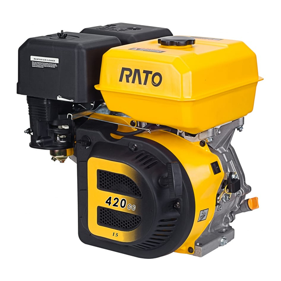
1. INTRODUCTION 1-1 PARTS DESCRIPTION Fuel tank cover Air cleaner Fuel tank Muffler Throttle grip Spark plug Recoil starter Choke lever Start handle Drain plug Oil dipstick... -
Page 8: Specification
1-2 SPECIFICATION Model R100 R160 items L×W×H 310×290×320mm 390×320×345mm Dry Weight 8.8 kg 15.5kg Engine Type 4-stroke, OHV, single cylinder Displacement 98 cm3 163cm3 Compression Ratio 8.5±0.3:1 Bore×Stroke 56×40 mm 68×45mm Maximum Output Power 1.8/3600 rpm 3.4kW/3,600rpm Maximum Torque 4.7N·m/2500rpm 9N·m/2,500rpm... - Page 9 Dry Weight 16.5 kg 16.5kg Engine Type 4-stroke, OHV, single cylinder Displacement 212 cm3 223cm3 Compression Ratio 8.5±0.3 Bore×Stroke 70×55 mm 70×58mm Maximum Output Power 4.2/3600 rpm 4.4kW/3,600rpm Maximum Torque 12N·m/2500rpm 13N·m/2,500rpm Cooling System Forced Air-cooled Ignition System Transistorized Magneto Ignition(TCI) BPR6ES(NGK),NHSP LD F7RTC,F7TC Spark Plug Lubrication System...
- Page 10 8.2:1 8:1 Compression Ratio Bore×Stroke 80×60mm 88×64mm Maximum Output Power 6kW/3,600rpm 7.6kW/3,600rpm Maximum Torque 18N·m /2,500rpm 23N·m /2,500rpm Cooling System Forced Air-cooled Ignition System Transistorized Magneto Ignition(TCI) BPR6ES(NGK),NHSP LD F7RTC,F7TC Spark Plug Lubrication System Forced Splash PTO Shaft Rotation Counterclockwise Model R420 R440...
-
Page 11: Service Limit
1-3 SERVICE LIMIT 1-3-1 R100 Parts Item Standard Value Service Limit 3850rpm Maximum Speed (No load) Gasoline Engine Cylinder Compression 0.9Mpa(1400rpm) Cylinder Cylinder Bore I.D. 56-56.015mm 56.165 Cylinder Warpage Head Skirt O.D. 55.975-55.985mm 55.9 Piston-to-Cylinder Clearance 0.015-0.04mm 0.12 Piston Piston Pin Bore I.D. 14 .002-14.008mm 14.048 Piston Pin O.D... - Page 12 29.4mm 29.2 Journal O.D 12.966-12.986mm 12.91 Crankcase Camshaft Holder I.D. 13.0-13.018mm 13.048 Cover 1-3-2 R160/R200 Parts Item Standard Value Service Limit 3750-3810rpm Maximum Speed (No Load) Gasoline Engine Cylinder Compression ≧1.17Mpa(1400rpm) Cylinder Cylinder Bore I.D. 68.0mm 68.165mm Cylinder Warpage 0.10mm Head Skirt O.D.
- Page 13 34.0mm 32.5mm Spring Free Length Cam Height 27.7mm 27.45mm Camshaft 27.75mm 27.50mm Journal O.D 13.984mm 13.916mm Crankcase Camshaft Holder I.D. 14.0mm 14.048mm Cover Main Jet 0.85 Carburetor Float Height 13.7±1.5mm Pilot Screw Opening 2-1/8 circle Spark Plug Gap 0.7-0.8mm Spark Plug Resistance 7.5-12.5kΩ...
- Page 14 Big End Oil Clearance 0.040-0.063mm 0.12mm Small End Side Clearance 0.1-0.7mm 1.1mm Crankshaft Crankshaft pin O.D 29.98mm 29.92mm Valve Clearance 0.15±0.02mm 0.20±0.02mm Stem O.D 5.48mm 5.318mm 5.44mm 5.275mm Valve Guide I.D 5.50mm 5.572mm IN/EX Stem-to-Guide Clearance 0.02-0.044mm 0.1mm 0.06-0.087mm 0.12mm Seat Width 0.8mm 2.0mm...
- Page 15 Piston Pin Bore I.D. 18 .002mm 18.048mm Piston Pin O.D. 18.0mm 17.954mm Piston Pin-to-Piston Pin Bore Clearance 0.002-0.014mm 0.06mm Ring Side Clearance: Top /Second Ring 0.015-0.045mm 0.15mm Oil Ring Ring End Gap: Top /Second Ring 0.2-0.4mm 1.0mm Piston Rings Oil Ring 0.15-0.35mm 1.0mm 1.5mm...
- Page 16 5.9-7.1kΩ Secondary Coil 0.4-0.6mm Air gap 1-3-5 R270 Parts Item Standard Service limit Maximum speed (No load) 3150-3180rpm Engine Cylinder compression ≧1.37Mpa(1400rpm) Cylinder Sleeve I.D. 77-77.017mm 77.17mm head Cylinder Warpage 0.10mm head Skirt O.D. 76.965-76.985mm 76.85mm Piston-to-cylinder clearance 0.015-0.052mm 0.12mm Piston Piston pin bore I.D.
- Page 17 39.0mm Cam height 32.9-33.1mm 32.88mm camshaft 32.50-32.70mm 32.48mm Journal O.D 15.966-15.984mm 15.92mm Crankcase Camshaft holder I.D 16.0mm 16.048mm cover Main jet 0.88 Carburetor Float height 13.2mm Pilot screw opening 2-7/8 turns Spark plug Gap 0.7-0.8mm Spark plug Resistance 7.5-12.5kΩ Resistance Primary coil 0.6-0.9Ω...
- Page 18 Big end I.D 33.225-33.239mm 33.27mm Big end oil clearance 0.013-0.03mm 0.12mm Big end side clearance 0.25-0.65mm 1.0mm Crankshaft Crankshaft pin O.D 33.175-33.185mm 33.12mm Valve clearance 0.10-0.15mm 0.15-0.20mm Stem O.D. 6.575-6.59mm 6.44mm 6.535-6.55mm 6.4mm Valves Guide I.D. IN/EX 6.6-6.615mm 6.66mm Stem clearance 0.01-0.04mm 0.10mm 0.05-0.08mm...
- Page 19 Skirt O.D. 79.975-79.985mm 79.85mm Piston-to-cylinder clearance 0.015-0.04mm 0.12mm Piston Piston pin bore I.D. 15 .002-15.008mm 15.242mm Piston pin O.D. 14.992-14.998mm 14.95mm Piston pin-to-piston pin bore clearance 0.004-0.016mm 0.08mm 0.025-0.06mm 0.15mm Ring side clearance: first/ second 0.20-0.40mm 1.0mm Piston rings Ring end gap: first/second 0.30-0.50mm 1.0mm...
- Page 20 Spark plug Resistance 9.5-10.5kΩ Resistance Primary coil 0.6-0.9Ω Ignition coil Secondary coil 5.6-6.9kΩ Air gap 0.3-0.5mm 1-3-8 R390 Parts Item Standard Service limit Maximum speed (No load) 3750-3810rpm Engine Cylinder compression ≧1.37Mpa(1400rpm) Cylinder Sleeve I.D 88-88.017mm 88.17mm head Cylinder Warpage 0.10mm head Skirt O.D.
- Page 21 0.05-0.077mm 0.13mm 1.1mm 2.0mm Seat width 39.0mm 37.5mm Spring free length 33.6-33.8mm 33.58mm Cam height camshaft 32.90-33.10mm 32.88mm Journal O.D 15.966-15.984mm 15.92mm Crankcase Camshaft holder I.D 16.0mm 16.048mm cover Main jet 0.92 Carburetor Float height 13.2mm Pilot screw opening 1-7/8 turns Spark plug Gap 0.7-0.8mm Spark plug...
- Page 22 3.7-3.9 mm 1.37mm Ring width: first/second 2.95-3.15 mm 2.0mm Small end I.D 20.011-20.022 mm 20.07mm Big end I.D 36.025-30.039 mm 36.07mm Connecting Big end oil clearance 0.25-0.65 mm 0.12mm Big end side clearance 0.013-0.03 mm 1.0mm Crankshaft Crankshaft pin O.D 35.975-35.985 mm 35.92mm Valve clearance...
- Page 23 head Cylinder Warpage 0.10mm head Skirt O.D. 91.96-91.97 mm 91.85mm Piston-to-cylinder clearance 0.03-0.055 mm 0.27mm Piston Piston pin bore I.D. 20.002-20.008 mm 20.042mm Piston pin O.D 19.992-19.997 mm 19.95mm Piston pin-to-piston pin bore clearance 0.004-0.016 mm 0.08mm Ring side clearance: first/ second 0.02-0.06mm 0.15mm Ring end gap:...
- Page 24 Pilot screw opening Spark plug Gap 0.7-0.8mm Spark plug Resistance 9.5-10.5kΩ Resistance Primary coil 0.6-0.9Ω Ignition coil Secondary coil 5.6-6.9kΩ Air gap 0.3-0.5mm...
-
Page 25: Dimensions And Torque
2. DIMENSIONS AND TORQUE 2-1 ENGINE DIMENSIONS 2-1-1 R100 2-1-2 R160/R180/R200/R210/R225... -
Page 26: R270/R280/R300
2-1-3 R270/R280/R300... -
Page 27: R390/R420/R440
2-1-4 R390/R420/R440... -
Page 28: Torque Values
2-2 TORQUE VALUES 2-2-1 torque values Ser. Part description and Torque MODEL Part Connecting components specifications value R100 M10×1.5×15 8.8-A Oil drain plug-flat R160-R225 M10×1.5×15 8.8-A 22±2 Oil drain plug washer-crankcase R270-R440 M12×1.5×18 8.8-A R100 M6×14 8.8-A R160-R225 M6×14 8.8-A 8±2... - Page 29 R270-R440 head subassembly Spark plug-cylinder head R100-R440 M14×1.25 28±2 Spark plug subassembly R100 M6×10 8.8-A Cylinder Cylinder shroud-cylinder R160-R210 M6×8 8.8-A 10±2 shroud head subassembly R270-R4440 M6×12 8.8-A R100 R160-R225 M6×16 8.8-A 10±2 Lower shield Lower shield- crankcase R270-R440...
-
Page 30: Standard Torque Values
R270-R440 M6×30 8.8-A 2-3 STANDARD TORQUE VALUES Torque valve Item Specifications N·m Kg·m 5mm bolt, nut 0.55 6mm bolt, nut Standard 8mm bolt, nut torque 10mm bolt, nut 37.5 3.75 12mm bolt, nut... -
Page 31: Maintenance
3. MAINTENANCE 3-1. MAINTENANCE SCHEDULE Good maintenance is essential for safe, economical, and trouble-free operation. It will also help reduce air pollution. Exhaust gas contains poisonous carbon monoxide. Shut off the engine before performing any maintenance. If the engine must be running during maintenance, make sure the area is well ventilated. -
Page 32: Engine Oil
2)Tighten the oil drain plug Oil drain plug See 2-2-1Maintenance Standard 3)Add the clean oil from the filler neck. R100 Oil capacity 0.35L R160/R180/R200/R210/R225 Oil capacity 0.6L R270/R300/R390/R420 Oil capacity 0.6L General oil: SAE15W-40 SJ class or equivalent API classified SJ class SAE10W-30 oil. -
Page 33: Air Cleaner
3-3 AIR CLEANER Dual element type Paper 1) Remove the nut, air cleaner cover and Air cleaner element wing nut. Remove polyurethane and paper cover elements. Wing nut 2) Clean polyurethane with detergent, then, blow it dry with compressed air or Polyurethan squeeze it dry. -
Page 34: Spark Plug Cleaning And
3-5 SPARK PLUG CLEANING AND Spark plug gap Side electrode ADJUSTING Wire brush 0.7-0.8mm 1)Remove carbon or other deposits with a stiff wire brush. Check gasket for damage. 2 ) Measure plug gap between center electrode and side electrode with a spark plug feeler. -
Page 35: Governor
and valve to measure valve clearance. IN:0.15 ± 0.02 mm Valve clearance EX:0.20 ± 0.02 mm 4 ) If adjustment is necessary, proceed as follows: a.Hold the rocker arm pivot and loosen the valve lock nut Throttle lever l1miting screw b.Turn the rocker arm pivot to obtain the specified clearance. -
Page 36: Disassembling And Servicing
4. DISASSEMBLING AND SERVICING 4-1 TROUBLESHOOTING 4-1-1 Hard starting TROUBLE CAUSE REMEDY There is no enough fuel in fuel Add fuel, open fuel cock. tank and fuel cock is closed. Unclog air vent. Air vent in the fuel tank cover is clogged Fuel supply is not Improper or clogged main... - Page 37 Too much carbon deposit Clear away. and dirt around electrodes. Spark Normal high Electrodes are burned badly plug is in Replace spark plug. –tension or insulators are damaged. poor cord spark. conditions Improper electrode gap. Adjust to proper value. al fuel supply High –tension cord is Replace...
-
Page 38: Engine Lacks Power
Ÿ Turn the fuel cock to “OFF” position, and drain the gasoline of the carburetor. Ÿ Remove the spark plug and spark plug cap. Ÿ Pull the recoil start handle to drive off the gas out of the cylinder. Ÿ Install the spark plug cap. -
Page 39: Speed Is Unstable
Ÿ Drain the oil of the fuel tank. Ÿ Drain the gasoline by loosening the fuel drain plug of the carburetor. Ÿ Remove the spark plug cap and spark plug and install the cylinder pressure meter. Ÿ Forcibly pull the recoil starter several times and measure compression force(≥0.4MPa) 4-1-3 Speed is unstable TROUBLE CAUSE... -
Page 40: Exhaust Gas Color Is Abnormal
TROUBLE CAUSE REMEDY 1.Check the battery Improper connection Correct the connection connection Wrong gasoline engine, or battery is charged Check or replace rectification circuit, insufficiently, battery is stored long without 2. Check battery charge the battery with a special being used, and pole plate’s sulphation is charger or replace the battery. -
Page 41: Oil Alert System Malfunction
Side electrode of spark plug Replace spark plug has dropped out High-tension cord has Weld it on dropped out Ignition coil is punctured or Replace ignition coil short-circuited Stop engine wire is located Find out the meeting position, on engine body separate them and insulate Cylinder is seriously scored Others... -
Page 42: Preparation Of Servicing
Oil insufficient or wrong oil/gasoline ratio Add engine oil Exhaust pipe is blocked Clean exhaust pipe Shroud is leaking Repair damaged part Cooling fins are blocked by foreign matter Clear cooling fins Cooling fan is loose and malfunctioning Reinstall it well Connecting rod deformation to make piston Gasoline engine is Replace connecting rod... - Page 43 walls or other equipment, keep away from inflammables such as gasoline, matches and so on to avoid possibility of fire. 8. Refuel in a well-ventilated area with the engine stopped, and in places refueling or storing gasoline, no smoking and any flames or sparks. 9.
- Page 44 4. Trademark label 5. Throttle control label 6. Air cleaner maintenance label 7. Choke lever, fuel cock label 8. Oil grade label...
- Page 45 9. Oil filling label...
- Page 46 Special tools 4-2-2 Tool name Application note 1. Float level gauge Carburetor float level inspection. 2. Valve guide driver Valve guide removal, installation. 3. Retainer assembler Assembling ball bearing. 4. Assembler handle Installing handle and bearing. 5. Inner retainer assembler Assembling ball bearing and time gear.
-
Page 48: Disassembling Chart
4-3 DISASSEMBLING CHART Engine Carburetor Flywheel Starter motor Shroud Recoil starter Air cleaner... -
Page 49: Engine
4-4 ENGINE a. Disassembly, reassembly Fan cover (only used for automatic starter) Control (only Lead support (2) used automatic Disassembly, reassembly: starter) Assembling: Insert it into fan cover Disassemble and reassemble with the recoil Ignition coil lead (black) starter assembled. Engine switch Starter relay lead Disassembly:... -
Page 50: Recoil Starter
4-4-1 Recoil starter Driving guide Guide tray screw Spring Drive cam Starter coil spring Returning spring Starter reel NOTICE: Wear gloves and eye protection during disassembling, and take care not to allow the return spring to come out ① Insert the recoil starter rope through the groove in the recoil starter reel and make a figure-eight knot at the rope end ②... - Page 51 . Set the recoil starter coil spring’s outside hook to the groove of the recoil starter reel. Groove Groove . Set the starter drive cam on the recoil starter reel, and install the return spring on the recoil starter reel while hooking it to the side of the driving cam.
-
Page 52: Flywheel
4-4-2 Flywheel High tension cord (check Flywheel the insulation for chap and Spark plug cap damage) replace Starter pulley necessary) Igniter stop wire Impeller Ignition coil Bolt a) Remove the fuel tank, air cleaner, carburetor and recoil starter assy. b) Measure the clearance between the ignition coil IGNITION COIL and flywheel with the feeler. - Page 53 (Secondary side) Measure the resistance of the secondary side of the coil with the spark plug cap removed, touch one test lead to the high tension cord while touching the other test lead to the coil’s iron core. Secondary side resistance value: 5-7kΩ(recommended value) Measure the resistance of the spark plug cap by attaching one ohmmeter lead to the wire end of the plug cap while touching the other test lead to the spark plug end.
-
Page 54: Air Cleaner
4-4-3 Air cleaner Wing Air cleaner cover Reassembly: after reassembling the element and grid into the cover, install the cover to the body Air cleaner Air cleaner element element (paper) Air cleaner grid Air cleaner element (polyurethane) Noise silencer 6×20mm (only for silence) Washer-bolt Elbow seal... - Page 55 Oil bath type Wing nut Air cleaner cover Air cleaner element (polyurethane) Air cleaner grid Air cleaner case Oil capacity: 60cc Reassembly: After cleaning with solvent, fill with clean oil and install Collar Elbow packing Air cleaner elbow Disassembly/reassembly: ·Remove and install with the choke lever in “ON”...
-
Page 56: Carburetor
4-4-4 Carburetor Carburetor insulator a.Disassembly/reassembly Reassembly: Blow out the passages with compressed air and install, noting Governor rod installation direction. After Throttle return installation, connect the high tension spring cord and fuel hose to the ground. Carburetor gasket Choke handle Insulator gasket Carburetor assy. - Page 57 b.Disassembly/reassembly CAUTION ·Remove the drain plug and drain the carburetor before disassembling ·Prohibit fire. Idle speed mixed ratio adjusting screw Choke lever reassembly: Inspect for wear before installation. Fuel cock Idle speed adjusting screw Float spring Main nozzle Reassembly: Reassembly: Clean thoroughly with Check for top wear or compressed air before...
- Page 58 Inspection ●Float level height Place the carburetor in the position as shown and push the float in by finger and measure the distance between the float top and carburetor body (float height). Specified float height See 1-3Maintenance Standard If the float height is out of specification, replace the float valve and recheck the float height Float level gauge...
-
Page 59: Cylinder Head /Valve
4-4-5 Cylinder head /valve 1) Removal/ installation Remove the fuel tank Remove the air cleaner Remove the recoil starter and shroud Remove the carburetor and insulator Spark plug: Clean and Stud adjust spark plug before installation EX valve guide Cylinder head Cylinder head... - Page 60 Valve spring retainer: Push down on the valve spring and move the retainer to the side so that valve stem slips through the side hole Do not remove the valve spring retainers while the cylinder head is installed to the cylinder, or the valves will drop into the cylinder.
- Page 61 Standard Service limit See 1-3Maintenance Standard See 1-3Maintenance Standard Valve guide Inspect: a) Inspect the valve guide for smoothness, scratch and damage in the inner surface, and matching between the valve guide and cylinder cover for fastness. VALVE GUIDE b) Use the valve guide reamer, ream REAMER the valve guides to remove any carbon deposits before measuring.
- Page 62 Replacement: a) Chill the replacement valve guides in the freezer section of a refrigerator for about an hour. b) Drive the valve guide out of the combustion chamber side using valve guide driver. CLIP VALVE GUIDE DRIVER Valve guide Installation height NOTICE: Be careful to avoid damaging the cylinder head when driving out the valve guides.
- Page 63 Reamer: For best results, be sure the cylinder head is at room temperature before reaming valve guides. a) Coat the reamer and valve guide with cutting oil. b) Rotate the reamer clockwise through the valve guide for the full length of the reamer. Continue to rotate VALVE the reamer clockwise while removing it from the GUIDE...
- Page 64 Valve seat: a) Thoroughly clean the combustion chambers and valve seats to remove carbon deposits. Apply a light coat of red lead powder or erasable color VALVE painting to the valve faces. FACE Insert the valves, and then press the valve several times forcefully.
-
Page 65: Crankshaft/Piston
4-4-6 Crankshaft/piston Oil seal Pin(Fix the governor arm with Ÿ Don’t reuse Ÿ Apply oil to lip of the oil seal pin after installing) Washer Install it inside the seat. Crankcase cover Bolt Governor arm Gasket (Don’t reuse) Oil seal Oil seal Crankcase Piston... - Page 66 Bearing gasket(Don’t reuse) Crankcase cover Oil filter cap Oil dipstick Sealing ring Seal ring Oil seal Bolt (Don’t damage the edge of the oil seal when reassembling crankcase cover ) Pin(Fix the governor Piston arm with pin after Oil seal pin clip Spacer installing)...
- Page 67 Disassembly: a) Piston 120° Marker marking • Install with the marker marking facing upward as shown. • Do not interchange the first ring and the First ring second ring (first ring is chrome plated) • After assembly, check for smooth movement Second “...
- Page 68 Piston check Check the piston and cylinder for contacting, and check the groove for defects, piston top for burn and cracks. If any of them is damaged, replace it. Clean the carbon deposit Clean the deposit round the piston top and cylinder neck before checking, first soak the carbon deposit with kerosene, then clean with a metal scraper or metal brush.
- Page 69 c) Piston-to-cylinder clearance Difference between cylinder maximum diameter and piston skirt should be considered as piston-to-cylinder clearance. NOTICE: This clearance must be checked before and after repairing. Check with piston upside down in the cylinder, and inserting feeler between piston skirt bearing face and wall, then pull the feeler out, if feeling resistance and moving smoothly out, the thickness of the feeler shall be considered as piston-to-cylinder clearance.
- Page 70 Standard Standard Check connecting rod If connecting rod is bent or twisted, or its big end shaft hole and small end hole have apparent grooves, or have cracks on one side, the connecting rod should be rejected and replaced with a new one. a) Check small end diameter If it is out of the standard or exceeds service limit, replace the connecting rod.
- Page 71 Ÿ Remove connecting rod and measure with plastic gauge. Ÿ If the clearance exceeds the service limit, replace the connecting rod and recheck the clearance. PLASTIC GAUGE WITH SCALE PLASTIC GAUGE Standard Service limit See 1-3Maintenance Standard See 1-3Maintenance Standard Camshaft check The camshaft is main driving part of the valve timing mechanism, which controls the intake and exhaust valves’...
- Page 72 Camshaft wearing cause and its influence on engine performance: Poor lubrication, caused by factors such as low oil viscosity, too many impurities, and little recycling oil, will result in camshaft abnormal wearing, making it hard for the camshaft surface to have a complete oil film, causing the camshaft surface seriously worn in the state of high-speed rubbing;...
-
Page 73: Starting Control Box
4-4-7 Starting control box a. Disassembly/reassembly (Only for starter) 6×12mm(2) Silicon rectifier Blade type fuse (5A) Control box screw Check : 7-8 Reassembly: Check for burn before installation... -
Page 74: Engine Switch
Oil alert Check: P.7-8 Reassembly: Install by aligning with the hole of the control plate Control panel Box installation bracket Switch Check: Reassembly: Install with the tab of the thread aligning Resetting button(1A) with notch of the control panel. Reassembly: Be careful not to install the left and right side plate reverse. - Page 75 ● Engine switch (with oil alert) Black lead Check the continuity between black lead and engine switch. Switch position Continuity ● Switch (with starter) Check continuity between leads when switch is kept at each position. Lead color (to grounding) Black/red Black/white White Switch position...
- Page 76 Yellow Yellow─ battery(-) (Don’t connect the positive and negative poles wrongly) ※ Don’t use the battery with over 6V, if so, bulb will break. Black /red lead ● Connect the black/red and yellow leads to 6V battery or dry cell, check whether the alert lamp lights up.
- Page 77 control box starter motor starter relay charging coil...
- Page 78 Ch on gq ing Rato Power Manu factu rin g Corp oratio n Add:No. 99 Jiujiang Road, Shuangfu District, Chongqing China service hotline:400-681-9981 fox:023-85553450 postcode:402247 URL:www.rato.cc E-mail: ratoservice@rato.cc (consultation customer service) parts@rato.cc (parts order)...
Need help?
Do you have a question about the R160 and is the answer not in the manual?
Questions and answers
On the R420D 14hp engine....can you measure crankcase oil capacity with the dipstick in the plug hole on the opposite side of engine? By the picture it looks like the two threaded holes are at the same level. On image below right click and select magnify.
Yes, the crankcase oil capacity of the Rato R160 engine can be checked using the oil dipstick, which is inserted into the plug hole on the opposite side of the engine.
This answer is automatically generated