Table of Contents
Advertisement
Quick Links
Technische Alternative RT GmbH
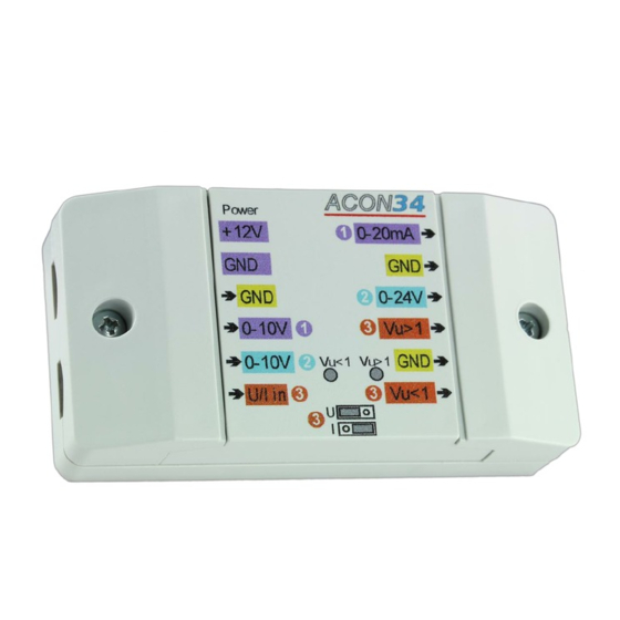
Analogue signal converter
This device has been designed to adjust signals between UVR controllers and third party
devices or industrial sensors.
It can be used to convert different signal levels or current into voltage and vice versa. Thanks
to input filters, PWM signals can also be converted into analogue values.
Conversion of 0-10 V signal into a 0-24 V signal
Conversion of 0-10 V signal into a 0-20 mA current
Freely usable level converter (input: 0-10 V or 0-20 mA), converts input into a voltage
signal with a transfer ratio that can be adjusted using two potentiometers and a jumper
Conversion of a PWM signal (500 Hz to 1 kHz/10 V) into a 0-10 V signal
A-3872 Amaliendorf, Langestr. 124
Tel +43 (0)2862 53635
mail@ta.co.at
ACON 34
Vers. 1.00 EN
Advertisement
Table of Contents

Related Manuals for TA ACON 34

Summary of Contents for TA ACON 34
- Page 1 Technische Alternative RT GmbH ACON 34 A-3872 Amaliendorf, Langestr. 124 Tel +43 (0)2862 53635 mail@ta.co.at Vers. 1.00 EN Analogue signal converter This device has been designed to adjust signals between UVR controllers and third party devices or industrial sensors. It can be used to convert different signal levels or current into voltage and vice versa. Thanks to input filters, PWM signals can also be converted into analogue values.
- Page 2 Power supply +12 V The converter is supplied by the 12 V connection of a freely programmable controller or by an external power supply unit (12 V). Regardless of the connection, the PCB is protected against short circuits for one minute. A resettable fuse (0.5 A) is installed internally upstream of the supply input.
- Page 3 0-10 V to 24 V converter Some boiler manufacturers use a 0-24 V signal in their products, which this converter supplies. Accuracy +/- 0.5 V at an internal resistance of the boiler controller of > 3 k Earth Earth 0-24 V signal 0-10 V signal...
- Page 4 3.1.1. Voltage division The output supplies 1 to 0.2 times the value of the input signal. The division value is set at the left-hand potentiometer. The potentiometer setting must be established by taking measurements with a multimeter. Earth Earth 0-10 V signal Voltage division Jumper position "U"...
- Page 5 3.2.2. Current division The output signal is 1 to 0.2 times the value of 2.2 V. Example: Division by a factor of 0.2 A 20 mA input signal (maximum value) is issued as one fifth of the 2.2 V voltage, i.e. as 0.44 V.
- Page 6 Dimensions in mm Top-hat rail installation (support rail TS35 to standard EN 50022) Technical data Input resistance of all stages at 0-10 V Approx. 50 k Output impedance of all stages Terminal area Max. 1.5 mm² IP rating IP 40 Max.
- Page 8 Technische Alternative RT GmbH A-3872 Amaliendorf Langestrasse 124, Austria Tel ++43 (0)2862 53635 Fax ++43 (0)2862 53635 7 Email: mail@ta.co.at www.ta.co.at © 2017...
Need help?
Do you have a question about the ACON 34 and is the answer not in the manual?
Questions and answers