Table of Contents
Advertisement
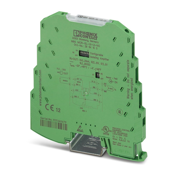
MINI MCR-SL-UI-UI
Configurable 3-way isolating amplifier
Data sheet
101945_en_05
1
Description
The 6.2 mm wide MINI MCR-SL-UI-UI... is a configurable 3-
way isolating amplifier. It is used to electrically isolate, condi-
tion, amplify, and filter standard signals.
The standard analog signals 0...20 mA, 4...20 mA, 0...10 V,
2...10 V, 0...5 V or 1...5 V are available electrically isolated on
the input and output sides.
The DIP switches, which can be accessed on the side of the
housing, are used to configure the input and output signal
ranges.
The power supply (19.2 ... 30 V DC) can be supplied either via
connection terminal blocks "3"/"4" or "7"/"8" on the modules
or in conjunction with the DIN rail connector. Please refer to
the section titled "Power supply" for more information.
NOTE: Correct usage in potentially explosive areas
The module is a category 3 item of electrical equipment. It is absolutely vital to follow the instructions provided
here during installation and observe the information in the "Safety regulations and installation notes".
Make sure you always use the latest documentation.
It can be downloaded from the product at www.phoenixcontact.net/catalog.
This data sheet is valid for all products listed on the following page:
© PHOENIX CONTACT
2012-09-27
Features
–
Configurable 3-way isolating amplifier
–
Input and output signal range configurable via DIP
switches
–
Approval for Ex-zone 2 (nA)
–
Screw or spring-cage connection can be provided
–
Can be supplied configured or unconfigured
Advertisement
Table of Contents

Related Manuals for Phoenix Contact MINI MCR-SL-UI-UI


Summary of Contents for Phoenix Contact MINI MCR-SL-UI-UI
-
Page 1: Description
Data sheet 101945_en_05 © PHOENIX CONTACT 2012-09-27 Description The 6.2 mm wide MINI MCR-SL-UI-UI... is a configurable 3- Features way isolating amplifier. It is used to electrically isolate, condi- – Configurable 3-way isolating amplifier tion, amplify, and filter standard signals. -
Page 2: Table Of Contents
MINI MCR-SL-UI-UI Table of contents Description ..........................1 Table of contents ........................2 Ordering data .......................... 3 .......................... 3 Order key Technical data ......................... 4 Safety regulations and installation notes.................. 6 ......................... 6 Installation notes .................... 6 Installation in the Ex area (zone 2) Installation .......................... -
Page 3: Ordering Data
MINI MCR-SL-UI-UI Ordering data Description Type Order No. Pcs. / Pkt. MCR 3-way isolating amplifier, I/O can be configured via DIP switches, for MINI MCR-SL-UI-UI 2864383 the electrical isolation of analog signals, with screw connection, order con- figuration MCR 3-way isolating amplifier, I/O can be configured via DIP switches, for... -
Page 4: Technical Data
MINI MCR-SL-UI-UI Technical data Input Configurable/programmable Yes, preconfigured Voltage input signal 0 V ... 10 V 0 V ... 5 V 1 V ... 5 V 2 V ... 10 V Max. voltage input signal 30 V Current input signal 0 mA ... - Page 5 MINI MCR-SL-UI-UI General data Test voltage, input/output/supply 1.5 kV (50 Hz, 1 min.) Dimensions W / H / D 6.2 mm / 93.1 mm / 102.5 mm Type of housing PBT green Connection data Screw connection Spring-cage conn. Conductor cross section, solid 0.2 mm²...
-
Page 6: Safety Regulations And Installation Notes
MINI MCR-SL-UI-UI Safety regulations and installation notes Installation notes Installation in the Ex area (zone 2) – The category 3 device is suitable for installation in the – Observe the specified conditions for use in potentially ex- zone 2 potentially explosive area. It fulfills the require- plosive areas. -
Page 7: Installation
MINI MCR-SL-UI-UI Installation Block diagram Connection notes Sensor / Field PLC / DCS NOTE: electrostatic discharge! IN U,I OUT U,I The device contains components that can be active passive 4-wire damaged or destroyed by electrostatic dis- GND 1 GND 2 –... -
Page 8: Assembly
DIN rail connector into position in the correct direction: the snap-on foot should be at the bottom and the connec- tor on the left. Connecting the wires The MINI MCR-SL-UI-UI... is available with two types of con- nection: – Screw terminal blocks (MINI MCR-SL-UI-UI) -
Page 9: Configuration
DIP switches S1 and S2 are used to specify the combination of input and output standard signal ranges (see "Configura- tion table"). Standard Configuration If it is an "NC version" (MINI MCR-SL-UI-UI-NC or MINI MCR- SL-UI-UI-SP-NC), the device will have the following standard configuration: –... -
Page 10: Adjustment
Use the potentiometer to set the exact final value of the set output signal. Connection/application example Level gauge 0...10V 0...20mA GND1 GND2 Control system GND3 GND3 MINI MCR-SL-UI-UI Mains voltage Figure 6 Example application PHOENIX CONTACT GmbH & Co. KG • 32823 Blomberg • Germany 101945_en_05 www.phoenixcontact.com...
Need help?
Do you have a question about the MINI MCR-SL-UI-UI and is the answer not in the manual?
Questions and answers
Can the MINI MCR-SL-UI-UI isolation amplifier be used in an intrinsic safety system?
No, the Phoenix Contact MINI MCR-SL-UI-UI isolation amplifier is approved for use in Ex-zone 2 (nA), but it is not specified for use in intrinsic safety systems.
This answer is automatically generated