Table of Contents
Advertisement
Quick Links
User Manual
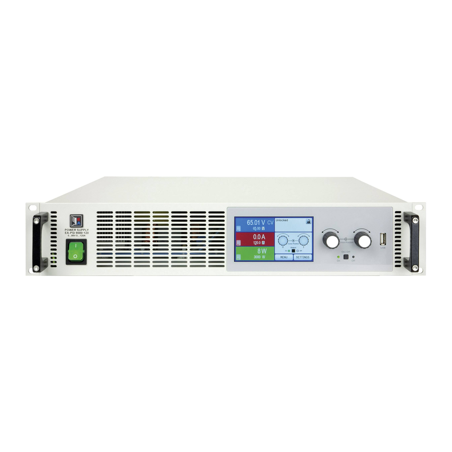
PSI 9000 2U Series
DC Laboratory Power Supply
Attention! This document is only valid for devices with
firmware "KE: 2.09" and "HMI: 2.01" and "DR: 1.6.3" or
higher. For availability of updates for your device check
our website or contact us.
THE POWER TEST EXPERTS
www.InteproATE.com
Version 2 July 2016
Advertisement
Table of Contents

Related Manuals for Intepro systems PSI 9000 2U Series

Summary of Contents for Intepro systems PSI 9000 2U Series
- Page 1 User Manual PSI 9000 2U Series DC Laboratory Power Supply Attention! This document is only valid for devices with firmware “KE: 2.09” and “HMI: 2.01” and “DR: 1.6.3” or higher. For availability of updates for your device check our website or contact us.
-
Page 3: Table Of Contents
Grounding of the DC output ......36 3.9.8 Trapezoidal function ........66 2.3.7 Connection of remote sensing ....37 3.9.9 DIN 40839 function ........66 2.3.8 Installation of an AnyBus interface module .38 3.9.10 Arbitrary function ..........67 PSI 9000 2U Series • DC Laboratory Power Supply • User Manual... - Page 4 Device firmware update (KE) ......84 Calibration ............85 4.4.1 Preface ............85 4.4.2 Preparation ...........85 4.4.3 Calibration procedure ........85 ACCESSORIES AND OPTIONS Overview ............87 SERVICE & SUPPORT General ............87 Contact options ..........87 © 2015 Intepro Systems, LP. Specifications subject to change without notice.
-
Page 5: About This Document
This document is to be delivered and kept with the equipment in case of change of location and/or user. 1.1.2 Copyright All information in this manual is copyrighted by Intepro Systems. Reprinting or copying in whole or part, and use of this manual for other purposes is forbidden and breach may lead to legal process. 1.1.3 Validity This manual is valid for the following equipment with TFT display panel, including derived variants. -
Page 6: Disposal Of Equipment
Claims of any sort because of damage caused by unintended use will not be accepted. • All damage caused by unintended use is solely the responsibility of the operator. © 2015 Intepro Systems, LP. Specifications subject to change without notice. -
Page 7: Safety
Additionally, anyone working with the equipment is responsible for ensuring that the device is at all times techni- cally fit for use. PSI 9000 2U Series • DC Laboratory Power Supply • User Manual... -
Page 8: Responsibility Of The Operator
Qualified persons are those who are able through training, knowledge and experience as well as knowledge of the specific details to carry out all the required tasks, identify dangers and avoid personal and other risks. © 2015 Intepro Systems, LP. Specifications subject to change without notice. -
Page 9: Alarm Signals
Colour TFT touch screen with gorilla glass, 4.3”, 480pt x 272pt, capacitive Controls: 2 rotary knobs with pushbutton functions, 2 pushbutton The nominal values for the device determine the maximum adjustable ranges. PSI 9000 2U Series • DC Laboratory Power Supply • User Manual... -
Page 10: Specific Technical Data
(2 RMS value: LF 0...300 kHz, PP value: HF 0...20MHz (3 Typical value at 100% output voltage and 100% power (4 The display error adds to the error of the related actual value on the DC output © 2015 Intepro Systems, LP. Specifications subject to change without notice. - Page 11 (3 For technical specifications of the analog interface see “3.5.4.3 Analog interface specification” on page 56 (4 Article number of the standard version, devices with options will have a different number PSI 9000 2U Series • DC Laboratory Power Supply • User Manual...
- Page 12 (2 RMS value: LF 0...300 kHz, PP value: HF 0...20MHz (3 Typical value at 100% output voltage and 100% power (4 The display error adds to the error of the related actual value on the DC output © 2015 Intepro Systems, LP. Specifications subject to change without notice.
- Page 13 (3 For technical specifications of the analog interface see “3.5.4.3 Analog interface specification” on page 56 (4 Article number of the standard version, devices with options will have a different number PSI 9000 2U Series • DC Laboratory Power Supply • User Manual...
- Page 14 (2 RMS value: LF 0...300 kHz, PP value: HF 0...20MHz (3 Typical value at 100% output voltage and 100% power (4 The display error adds to the error of the related actual value on the DC output © 2015 Intepro Systems, LP. Specifications subject to change without notice.
- Page 15 (3 For technical specifications of the analog interface see “3.5.4.3 Analog interface specification” on page 56 (4 Article number of the standard version, devices with options will have a different number PSI 9000 2U Series • DC Laboratory Power Supply • User Manual...
- Page 16 (2 RMS value: LF 0...300 kHz, PP value: HF 0...20MHz (3 Typical value at 100% output voltage and 100% power (4 The display error adds to the error of the related actual value on the DC output © 2015 Intepro Systems, LP. Specifications subject to change without notice.
- Page 17 (3 For technical specifications of the analog interface see “3.5.4.3 Analog interface specification” on page 56 (4 Article number of the standard version, devices with options will have a different number PSI 9000 2U Series • DC Laboratory Power Supply • User Manual...
- Page 18 (2 RMS value: LF 0...300 kHz, PP value: HF 0...20MHz (3 Typical value at 100% output voltage and 100% power (4 The display error adds to the error of the related actual value on the DC output © 2015 Intepro Systems, LP. Specifications subject to change without notice.
- Page 19 (3 For technical specifications of the analog interface see „3.5.4.3 Analog interface specification“ on page 56 (4 Article number of the standard version, devices with options will have a different number PSI 9000 2U Series • DC Laboratory Power Supply • User Manual...
- Page 20 (2 RMS value: LF 0...300 kHz, PP value: HF 0...20MHz (3 Typical value at 100% output voltage and 100% power (4 The display error adds to the error of the related actual value on the DC output © 2015 Intepro Systems, LP. Specifications subject to change without notice.
- Page 21 (3 For technical specifications of the analog interface see “3.5.4.3 Analog interface specification” on page 56 (4 Article number of the standard version, devices with options will have a different number PSI 9000 2U Series • DC Laboratory Power Supply • User Manual...
-
Page 22: Views
PSI 9000 2U Series 1.8.4 Views © 2015 Intepro Systems, LP. Specifications subject to change without notice. - Page 23 PSI 9000 2U Series PSI 9000 2U Series • DC Laboratory Power Supply • User Manual...
- Page 24 PSI 9000 2U Series Figure 5 - View from above, with DC cover (terminal type 1) © 2015 Intepro Systems, LP. Specifications subject to change without notice.
- Page 25 For the connection of standard USB sticks up to 32GB, formatted to FAT32. Value tables for the function generator (UI and IU functions) may be loaded or 100 arbitrary function sequences can be loaded or saved. PSI 9000 2U Series • DC Laboratory Power Supply • User Manual...
-
Page 26: Construction And Function
1.9.1 General description The electronic high performance power supplies of the PSI 9000 2U series are especially suitable for test systems and industrial controls because of their compact construction in a 19” enclosure with 2 height units (2U). Apart from basic functions of power supplies, set point curves can be produced in the integrated function generator (sine, rectangular, triangular and other curve types). -
Page 27: Scope Of Delivery
GPIB port. This option can be retrofitted upon request. The device will keep the GPIB interface USB and analog interfaces. The GPIB port can only support SCPI commands. PSI 9000 2U Series • DC Laboratory Power Supply • User Manual... -
Page 28: The Control Panel (Hmi)
A, V, kW 0-110% nom OVP, OCP etc., related to the physical values Valid also for values related to these physical units, such as OVD for voltage and UCD for current © 2015 Intepro Systems, LP. Specifications subject to change without notice. - Page 29 Pushbutton function of the knobs The rotary knobs also have a pushbutton function which is used in all menu options for value adjustment to move the cursor by rotation as shown: PSI 9000 2U Series • DC Laboratory Power Supply • User Manual...
- Page 30 The name must begin with pv, the rest can be user defined. fc<arbitrary>.csv FC (fuel cell) table for the XY function generator. The name must begin with fc, the rest can be user defined. © 2015 Intepro Systems, LP. Specifications subject to change without notice.
-
Page 31: Usb Port (Rearside)
0-5 V and 0-10 V, in each case for 0-100%. PSI 9000 2U Series • DC Laboratory Power Supply • User Manual... -
Page 32: Share Bus-Connection
The connection to a PC or other GPIB port is done using standard GPIB cables from stock, which can have straight or 90° connectors. If cable with 90° connectors is used the USB port will be inaccessible. © 2015 Intepro Systems, LP. Specifications subject to change without notice. -
Page 33: Installation & Commissioning
(see “1.8.3. Specific technical data”) • Before connecting to the mains ensure that the connection is as shown on the product label. Overvoltage on the AC supply can cause equipment damage. PSI 9000 2U Series • DC Laboratory Power Supply • User Manual... -
Page 34: Preparation
Preparation Mains connection for a PSI 9000 2U series device is done using the included 2-meter 3-pole mains cord. If a dif- ferent AC wiring is required, make sure that the other cable has a cross section of at least 2.5 mm² (AWG 12). -
Page 35: Connection To Ac Supply
M8 (8 mm) bolt on a brass block Screw clamp connection M6, on copper rail Recommendation: M8 ring lug with a 8.4 mm hole Recommendation: M6 ring lug with a 6.5 mm hole PSI 9000 2U Series • DC Laboratory Power Supply • User Manual... -
Page 36: Grounding Of The Dc Output
• If grounding one of the DC output poles check if any pole of the load is already grounded. This could lead to a short circuit! © 2015 Intepro Systems, LP. Specifications subject to change without notice. -
Page 37: Connection Of Remote Sensing
The sense cables must be connected + to + and - to - at the load, otherwise both systems may be damaged • In master-slave operation, the remote sensing should be connected to the master unit only Figure 7 - Example for remote sensing wiring PSI 9000 2U Series • DC Laboratory Power Supply • User Manual... -
Page 38: Installation Of An Anybus Interface Module
The analog interface is galvanically isolated from the device internally. Unless abso- lutely required, do not connect any ground of the analog interface (AGND) to the DC minus output as this will cancel the galvanic isolation. © 2015 Intepro Systems, LP. Specifications subject to change without notice. -
Page 39: Connecting The "Share" Bus
After a firmware update, return of the equipment following repair, or a location or configuration change, measures should be taken similar to those at initial start up. Refer to “2.3.12. Initial commission”. Only after successfully checking the device as listed should it be operated. PSI 9000 2U Series • DC Laboratory Power Supply • User Manual... -
Page 40: Operation And Application
CC and this message will be passed as a signal to the analog interface, as well stored as status which can also be read as a status message via digital interface. © 2015 Intepro Systems, LP. Specifications subject to change without notice. -
Page 41: Power Regulation / Constant Power / Power Limiting
Clarification: • With resistance mode being active, i.e. mode R/I, the function generator will be offline. • Resistance mode is not available during master-slave operation (MS). PSI 9000 2U Series • DC Laboratory Power Supply • User Manual... -
Page 42: Alarm Conditions
DC output exceeds the adjusted OPP limit. This function serves to protect the connected load application so that this is not overloaded and possibly damaged due to an excessive power consumption. © 2015 Intepro Systems, LP. Specifications subject to change without notice. -
Page 43: Manual Operation
The menu structure is shown schematically on the following pages. Some setting parameters are self-explanatory. The others will be explained on the following pages. PSI 9000 2U Series • DC Laboratory Power Supply • User Manual... - Page 44 PSI 9000 2U Series © 2015 Intepro Systems, LP. Specifications subject to change without notice.
- Page 45 PSI 9000 2U Series PSI 9000 2U Series • DC Laboratory Power Supply • User Manual...
- Page 46 PSI 9000 2U Series © 2015 Intepro Systems, LP. Specifications subject to change without notice.
- Page 47 “3.10.1. Parallel operation in master-slave mode (MS)” Device address This is used to define the device address in master-slave operation between 1 and 15 (for slaves), while the master always has 0. PSI 9000 2U Series • DC Laboratory Power Supply • User Manual...
- Page 48 Mail server address, used to send eMails via this mail server, in order to e.g. report an alarm. Settings Username Login to Mailserver, Username Password Login to Mailserver, Password © 2015 Intepro Systems, LP. Specifications subject to change without notice.
- Page 49 = 1024 Baud) as bus baud rate. Selection „AUTO“ will let the slave device wait for the master to initiate bus traffic in order to detect the baud rate on the bus automatically PSI 9000 2U Series • DC Laboratory Power Supply • User Manual...
- Page 50 HMI Update With this function the firmware for the control panel can be updated using a USB flash drive. For details refer to “4.3.1 HMI update” on page 84. © 2015 Intepro Systems, LP. Specifications subject to change without notice.
-
Page 51: Adjustment Limits (Limits)
P by direct input. See section 3.4.6. The actual operating mode, while the DC output is switched on, solely depends only on the set values. For more information see section „3.2. Operating modes“. PSI 9000 2U Series • DC Laboratory Power Supply • User Manual... -
Page 52: Manual Adjustment Of Set Values
Decimal values are set by tapping the point key. For example, 54.3 V is set with The display reverts to the main page and the set values take effect.. © 2015 Intepro Systems, LP. Specifications subject to change without notice. -
Page 53: Switching The Dc Output On Or Off
See the external documentation “Programming Guide ModBus & SCPI” if you are using custom software, or refer to the external documentation from LabView VIs or other software provided by the manufacturer. PSI 9000 2U Series • DC Laboratory Power Supply • User Manual... -
Page 54: Remote Control
Remote control is possible throough the built-in analog or USB port or using one of the optional interface modules (AnyBus CompactCom, only with standard models of PSI 9000 2U series) or via the GPIB port (only with option 3W installed). Important here is that only the analog or one digital interface can be in control. For example, if an attempt were to be made to switch to remote control through the digital interface while the analog remote control is active (Pin Remote = LOW), the device would report an error through the digital interface. -
Page 55: Remote Control Via The Analog Interface (Ai)
VREF (solder bridge or different), so it gives 100% The analog interface is galvanically separated from DC output. Therefore do not con- nect any ground of the analog interface to the DC- or DC+ output! PSI 9000 2U Series • DC Laboratory Power Supply • User Manual... - Page 56 ***** The error of a set value input adds to the general error of the related value on the DC output of the device 3.5.4.4 Overview of the Sub-D Socket © 2015 Intepro Systems, LP. Specifications subject to change without notice.
- Page 57 (front panel) or via command from digital interface. When trying to switch on, a popup in the display resp. an error message will be normal generated. PSI 9000 2U Series • DC Laboratory Power Supply • User Manual...
- Page 58 Example with potentiometers c) Reading actual values The AI provides the DC input values as current and voltage monitor. These can be read using a standard multimeter or similar. © 2015 Intepro Systems, LP. Specifications subject to change without notice.
-
Page 59: Alarms And Monitoring
The DC output will be switched off. OverTem- Triggers an alarm if the internal temperature reaches a certain limit. The Display, analog perature DC output will be switched off. IF, digital IF PSI 9000 2U Series • DC Laboratory Power Supply • User Manual... - Page 60 The set values can be entered using the ten-key tab. This will appear by tapping the touch area on the particular page, e.g. “4.1 Event U”, showing the rotary knob assignments. © 2015 Intepro Systems, LP. Specifications subject to change without notice.
-
Page 61: Control Panel (Hmi) Lock
In the selection screen (right) choose between user profile 1-5 in which the settings are to be saved. The profile will then be displayed and the values can be checked, but not changed. Save using the touch area PSI 9000 2U Series • DC Laboratory Power Supply • User Manual... -
Page 62: The Function Generator
300 W then, in this case, the current would be limited to 30 A and, if clamped to an oscilloscope, it could be seen as capped at 30 A and never achieve the target of 40 A. © 2015 Intepro Systems, LP. Specifications subject to change without notice. -
Page 63: Manual Operation
0. Only exception: when applying any function to the current (I), there is no adjustable static current value, so the function would always start from 0 A. PSI 9000 2U Series • DC Laboratory Power Supply • User Manual... -
Page 64: Sine Wave Function
Off = Offset, based on the foot of the triangular wave 0.1 ms...36000 s Rising edge time Δt of the triangular wave signal 0.1 ms...36000 s Falling edge time Δt of the triangular wave signal © 2015 Intepro Systems, LP. Specifications subject to change without notice. -
Page 65: Rectangular Function
1/25 Hz = 40 ms. For a duty cycle of 80% the pulse time (t1) is 40 ms*0.8 = 32 ms and the pause time (t2) is 8 ms. PSI 9000 2U Series • DC Laboratory Power Supply • User Manual... -
Page 66: Trapezoidal Function
If the curve in sequence 4 should be a sine wave, then these 5 sequences have to be transferred to the arbitrary generator. Sequences © 2015 Intepro Systems, LP. Specifications subject to change without notice. -
Page 67: Arbitrary Function
1 Hz, there would be exactly 1 sine wave. If the time were 0.5 s at the same frequency, there would only be a half sine wave. Seq.time PSI 9000 2U Series • DC Laboratory Power Supply • User Manual... - Page 68 (AC) will be created and only the DC settings will be effective. Here start and end values are unequal and a steadily increasing ramp is generated. Seq.time © 2015 Intepro Systems, LP. Specifications subject to change without notice.
- Page 69 Sequence 2: 3 Sine waves (relationship fre- quency to sequence time: 1:3) Sequence 3: Horizontal ramp (f = 0) Sequence 4: Falling ramp (f = 0) Sequence 1 Sequence 2 Seq. 3 Sequence 4 PSI 9000 2U Series • DC Laboratory Power Supply • User Manual...
- Page 70 The selected file is then checked and loaded, if valid. In case it is not valid, the device will show an error message. Then the file must be corrected and the steps repeated. © 2015 Intepro Systems, LP. Specifications subject to change without notice.
-
Page 71: Ramp Function
UI table. The UI function suits very good for the simulation of fuel cell characteristics. PSI 9000 2U Series • DC Laboratory Power Supply • User Manual... - Page 72 Once the file is accepted, you will be requested to remove the USB drive. Submit and load the function with to start and control it as with other function (also see „3.9.4.1. Function selection and control“). © 2015 Intepro Systems, LP. Specifications subject to change without notice.
-
Page 73: Pv Table Function (Photovoltaics)
(0%...100% in 1% steps, see screenshot below) helps to simulate different light situations from darkness (no power output) to the minimal amount of light that is required to make the panel provide full power. Umpp PSI 9000 2U Series • DC Laboratory Power Supply • User Manual... -
Page 74: Fc Table Function (Fuel Cell)
It means, the voltage has to decrease from point 1 to point 4, while the cur- rent has to increase. In case the rules are not followed, the device will reject the values with an error and reset them to 0. © 2015 Intepro Systems, LP. Specifications subject to change without notice. - Page 75 Without any load, the voltage will rise to the adjusted Uoc value. Stop the function run anytime as described in 3.9.4.1. PSI 9000 2U Series • DC Laboratory Power Supply • User Manual...
-
Page 76: Remote Control Of The Function Generator
The function generator is unavailable if R mode (resistance) is activated • Some functions are based on the arbitrary generator, some on the XY generator. Therefore, both generators have to be controlled and configured separately © 2015 Intepro Systems, LP. Specifications subject to change without notice. -
Page 77: Other Applications
Thus, if e.g. 5 units, each with a power of 1.5 kW, are connected together to a 7.5 kW system, then the master can be set in the range 0...7.5 kW. PSI 9000 2U Series • DC Laboratory Power Supply • User Manual... - Page 78 The initializing process of the master and the master-slave system will, as long as MS mode is still activated, be repeated each time the units are powered. The initialization can be repeated anytime via the MENU in GENERAL SETTINGS, PAGE: 9. © 2015 Intepro Systems, LP. Specifications subject to change without notice.
- Page 79 If multiple alarms happen simultaneously, the master only indicates the most recent one. In this case, the par- ticular alarms can be read from the slave units displays or via digital interface during remote control or remote supervision. PSI 9000 2U Series • DC Laboratory Power Supply • User Manual...
-
Page 80: Series Connection
In remote control, an almost synchronous control can be achieved by using any available Ethernet interface module and sending message as broadcast, so they address multiple units at once. © 2015 Intepro Systems, LP. Specifications subject to change without notice. -
Page 81: Two Quadrant Operation (2Qo)
E.U.T PSU, preferable PSU 1, has to be set to Master for the Share bus connection, whether MS operation through the digital MS bus is used or not. PSI 9000 2U Series • DC Laboratory Power Supply • User Manual... - Page 82 When reaching 27 V, the power supply will deliver only the current needed to maintain battery voltage. © 2015 Intepro Systems, LP. Specifications subject to change without notice.
-
Page 83: Service And Maintenance
Contact Intepro Systems for the steps to be taken. It may be necessary to return the device to Intepro Systems (with or without guarantee). If a return for checking or repair is to be carried out, ensure that: •... -
Page 84: Firmware Updates
The firmware of the device, if necessary, is updated via the rearside USB port. For this a software, a so-called “update tool” is needed which is available from Intepro Systems (as a download from our website or upon request), together with the firmware update. The update tool guides the user through the update process. -
Page 85: Calibration
The calibration procedure, as explained below, is an example with model PSI 9080-120 2U. Other models are treated the same way, with values according to the particular PSI model and the required load. PSI 9000 2U Series • DC Laboratory Power Supply • User Manual... - Page 86 Last but not least save the calibration data permanently by tapping Leaving the calibration selection menu without tapping “Save and exit” will discard calibration data and the procedure would have to be repeated! © 2015 Intepro Systems, LP. Specifications subject to change without notice.
-
Page 87: Accessories And Options
Repairs, if not otherwise arranged between supplier and customer, will be carried out by Intepro Systems. For this the device must be returned to Intepro Systems. No RMA number is needed. It is sufficient to package the equip- ment adequately and send it, together with a detailed description of the fault and, if still under guarantee, a copy of the invoice, to the following address. - Page 88 Contact Us United States United Kingdom China Intepro Systems, Inc. Intepro UK Ltd. Intepro Power 14712-A Franklin Ave 9 Lakeside Business Park Block 7 Fourth Industrial Area Tustin, CA 92780 Swan Lane, Sandhurst Berkshire Nanyou, Nanshan District Tel: 1-714-953-2686 GU47 9DN / UK Shenzhen, China 518052 sales@inteproate.com...
Need help?
Do you have a question about the PSI 9000 2U Series and is the answer not in the manual?
Questions and answers