Table of Contents
Advertisement
Quick Links
Advertisement
Table of Contents

Summary of Contents for Rishabh Instruments RISH Master 3430i
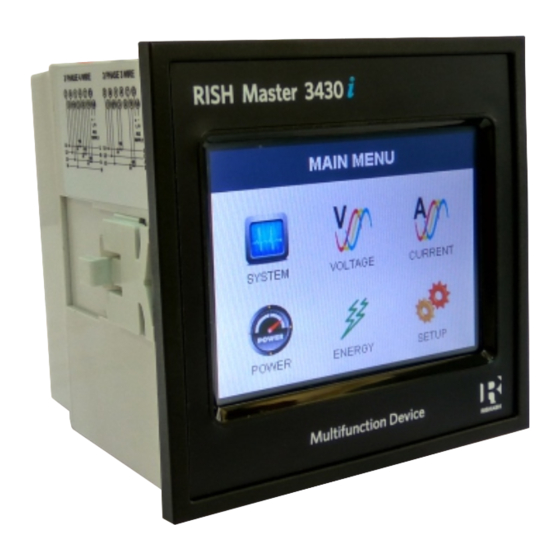
- Page 1 Operating Manual RISH Master 3430i RISH Master 3430i...
-
Page 3: Table Of Contents
INDEX Touch Screen Digital Multi-function Meter Installation & Operating Instructions Section Contents Introduction Measurement Reading Screens Programming 3.1 Password Protection 3.1.1 Change Password 3.2 Menu selection 3.2.1 System Parameter selection screen 3.2.1.1 System type 3.2.1.2 Potential transformer Primary value 3.2.1.3 Current transformer Primary value 3.2.1.4 Current transformer Secondary value 3.2.1.5 Auto Scrolling 3.2.1.6 Low current noise cutoff... - Page 4 3.2.3 Reset Parameter selection screen 3.2.3.1 Resetting Parameter 3.2.4 Output Option selection screen (menu) 3.2.4.1 Relay 1 output selection menu 3.2.4.2 Relay 2 output selection menu 3.2.4.3 Parameter setting for Analog Output-1 3.2.4.4 Parameter setting for Analog Output-2 3.2.5 Brightness & Contrast 3.2.6 RGB Color Code Touch screen calibration.
-
Page 5: Introduction
1. Introduction This instrument is a panel mounted 96 x 96mm DIN Quadratic Digital metering system for the measurement of important electrical parameters like AC voltage, AC Current, Frequency, Power, Energy(Active / Reactive / Apparent) . The instrument integrates accurate measurement of technology (All Voltage &... - Page 6 TABLE 1: Units of Measured Parameters Measurement Volts System Voltage Amps System Current Volts Voltage VL1-N(4wire only) Volts Voltage VL2-N(4wire only) Volts Voltage VL3-N(4wire only) ( for 3 / 4 wire) Volts Voltage VL1-L2 ( for 3 / 4 wire) Volts Voltage VL2-L3 ( for 3 / 4 wire)
-
Page 7: Measurement Reading Screens
Units of Measured Parameters Measurement ( for 3 / 4 wire) V1 THD* ( for 3 / 4 wire) V2 THD* ( for 3 / 4 wire) V3 THD* ( for 3 / 4 wire) I1 THD ( for 3 / 4 wire) I2 THD ( for 3 / 4 wire) I3 THD... - Page 8 Parameter Screens Single Phase MAIN MENU RESET CHANGE COMMUNICATION POWER ENERGY SYSTEM CURRENT VOLTAGE (Sec 3.2.4) (Sec 3.1) SYSTEM L1 PHASE ACTIVE LINE - NEUTRAL SYSTEM TYPE LINE CURRENT POWER PARAMETERS (Sec 3.2.1.1) IMPORT VOLTAGE SYSTEM Max. L2 PHASE ACTIVE PT PRIMARY LINE - LINE EXPORT...
-
Page 9: Main Menu
Parameter Screens 3 Phase MAIN MENU RESET CHANGE COMMUNICATION POWER ENERGY VOLTAGE SYSTEM CURRENT OPTIONS PASSWORD PARAMETERS (Sec 3.2.4) (Sec 3.1) L1 PHASE SYSTEM ACTIVE Line - Neutral SYSTEM TYPE Line Current POWER IMPORT (Sec 3.2.1.1) PARAMETERS VOLTAGE L2 PHASE ACTIVE SYSTEM Line - Line... - Page 10 Setup Parameter Screens PASSWORD RESET OUTPUT SYSTEM PARAMETERS BRIGHTNESS COMMUNICATION CHANGE COLOR OPTIONS PARAMETERS PARAMETERS PARAMETERS & CONTRAST PASSWORD (Sec 3.2.1) CODE RESET ALL SYSTEM TYPE RS485 RELAY OUTPUT 1 RESET ALL ENERGIES ADDRESS RESET MAX VOLTAGE & CURRENT RELAY OUTPUT 2 PT PRIMARY RESET MIN VOLTAGE &...
-
Page 11: Programming
3. Programming The following sections comprise step by step procedures for conguring the instrument for individual user requirements. To access the set-up screens touch on the “ SETUP ” icon in Main Menu. This will take the User into the Password Protection Entry Stage(Section 3.1). 3.1. -
Page 12: Change Password
3.1.1 Change Password Change Password Option is the second last option in list of “SETUP” submenu, so can be accessed by a simple touch on “ Change Password” button. In this screen user rst needs to enter the current password. After input of correct password, “PASSWORD ACCEPTED”... -
Page 13: System Type
3.2.3 RESET PARAMETERS 3.2.4 OUTPUT OPTIONS 3.2.5 BRIGHTNESS & CONTRAST Touching on SYSTEM PARAMETER will open the system parameters list screen.Then these screens from particular parameter may be scrolled through one at a time in incremental order by touching the “ key”... -
Page 14: Potential Transformer Primary Value
3.2.1.2 Potential Transformer Primary Value The nominal full scale voltage will be displayed as Line to Line Voltages for 3 Phase 3 wire and 3 Phase 4 wire and 1 Phase 2 wire for Single Phase. This screen can be accessed only from system parameters list menu. Here again 0 to 9 digit input keypad is provided to set value of PT Primary, &... -
Page 15: Current Transformer Secondary Value
The “Maximum Power” restriction of 666.6 MVA refers to 120% of nominal current and 120% of nominal voltage, i.e, 462.96 MVA nominal power per phase. Valid range of CT primary setting value is from 1 to 9999. If value outside the range is entered, It will display “INVALID VALUE” CT PRIMARY followed by correct range of parameter. -
Page 16: Low Current Noise Cutoff
While in Auto-scrolling mode, touch sense for entire screen will be disabled except for the top right most corner where “A” symbol would be displayed stating that meter is in Auto- scroll mode. Touching on “A” will show two options “ON” and “OFF”. Touching on “ON” will continue auto scrolling &... -
Page 17: Energy Digit Reset Count
3.2.1.10 ENERGY DIGIT RESET COUNT (ROLLOVER COUNT) This screen enables the user for setting maximum energy count after which energy will rollover to zero depending on the setting of Wh, kWh & Mwh in Energy resolution option. resolution If Energy is in WATT then rollover count can be from 7 to 14 DIGITS. -
Page 18: Address Setting
3.2.2 Communication Parameter Selection : After entering in the “COMMUNICATION PARAMETERS” list of following parameters will be displayed 3.2.2.1 RS485 ADDRESS 3.2.2.2 RS485 BAUD RATE 3.2.2.3 RS485 PARITY 3.2.2.1 RS485 Address Setting This screen applies to the RS 485 output only. This screen allows RS485 ADDRESS the user to set RS485 address parameter for the instrument. - Page 19 3.2.2.3 RS 485 Parity & Stop bit Selection This screen allows the user to set Parity & number of stop bits. Four options: ODD PARITY WITH ONE STOP BIT, NO PARITY RS485 PARITY & STOP BITS LINE-NEUTRAL VOLTAGE LINE-NEUTRAL VOLTAGE LINE-NEUTRAL VOLTAGE LINE-NEUTRAL VOLTAGE LINE-NEUTRAL VOLTAGE...
-
Page 20: Pulse Output
3.2.4. Output Option selection menu After entering in the “OUTPUT OPTIONS”, List of following parameters will be displayed :- 3.2.4.1 RELAY-1 3.2.4.2 RELAY-2 3.2.4.3 ANALOG-1 3.2.4.4 ANALOG-2 3.2.4.1 Relay1 output Selection menu This screen applies to the Relay1 Output option Selection . Touching any option will open screens of parameters LINE-NEUTRAL VOLTAGE LINE-NEUTRAL VOLTAGE... - Page 21 3.2.4.1.1.1 Assignment of Energy to pulse output (Relay 1) : This screen allows the user to assign energy to pulse output (for Relay 1) Following six options are displayed:- Apparent Energy Import Energy ( Active ) RELAY-1 ENERGY ASSIGNMENT LINE-NEUTRAL VOLTAGE LINE-NEUTRAL VOLTAGE LINE-NEUTRAL VOLTAGE LINE-NEUTRAL VOLTAGE...
- Page 22 3.2.4.2 Relay 2 Output Selection Conguration of Relay 2 for Pulse or Limit Output is same as Relay 1. If you Select the Pulse output option for Relay 1 same setting will be applicable for Relay 2 except assignment of energy to Pulse output (i.e. Energy assignment of both relay can be different.) 3.2.4.3 Parameter setting for Analog Output 1 ( Optional ) This option allows the user to set analog output 1 to corresponding measured parameter.
- Page 23 3.2.6 RGB Color Code (only for 3 Phase 3 Wire / 4 Wire) This screen allows user to set the values of Red, Green and Blue components of colors used to display the parameters of all three phases. RGB COLOR CODE Different colors can be assigned to each phase using combination of Red, Green and Blue component values.
-
Page 24: Touch Screen Calibration
4 Touch screen calibration This instrument is able to perform calibration to ensure the proper operation of the units touch screen functionalities. The calibration procedure will correct the problem of out of tolerance touch screen malfunction. Note that errors corrected by this calibration procedure are specic only to touch screen operation. - Page 25 Repeat the same After successful LINE-NEUTRAL VOLTAGE LINE-NEUTRAL VOLTAGE LINE-NEUTRAL VOLTAGE LINE-NEUTRAL VOLTAGE LINE-NEUTRAL VOLTAGE LINE-NEUTRAL VOLTAGE CT SECONDARY LINE-NEUTRAL VOLTAGE LINE-NEUTRAL VOLTAGE LINE-NEUTRAL VOLTAGE LINE-NEUTRAL VOLTAGE LINE-NEUTRAL VOLTAGE LINE-NEUTRAL VOLTAGE CT SECONDARY Hold screen for 1 sec procedure for the calibration, the after system reset to 1 AMPERE...
- Page 26 5. Analog Output ( optional ) : This module provides two d.c. isolated outputs .There are two output 1) Two 0 - 1mA outputs , internally powered . 2) Two 4 - 20mA outputs , internally powered . The 0 -1mA output module has an 0V return on each end of the 4 way connector ( Please refer section 15 for connection details ) On both modules the output signals are present on pins A1(Analog Output 1) &...
- Page 27 Diagram 2 : ( 0 - 1 mA ) 0 (0.5 mA) 270 (0.25 mA) 90 (0.75 mA) 181 (0 mA) 180 (1 mA) TABLE 2 : Parameter for Analog Range Parameter 3P 4W 3P 3W 1P 2W None ...
- Page 28 Range Parameter 1P 2W 3P 3W 3P 4W 0 - 120 % 8 ACTIVE POWER L2 9 ACTIVE POWER L3 0 - 120 % 0 - 120 % 10 APPARENT POWER L1 ...
- Page 29 6. Relay output (Optional) : This instrument is provided with either 1 or 2 relay for pulse output. 6.1 Pulse Output : Pulse output is the potential free, very fast acting relay contact which can be used to drive an external mechanical counter for energy measurement. This instrument’s pulse output can be congured to any of the following parameter...
- Page 30 TABLE 3 : Energy Pulse Rate Divisor 1.For Energy Output in Wh 2. For Energy Output in Kwh Pulse rate Pulse rate Divisor Pulse System Power* Divisor Pulse System Power* 1per Wh Up to 3600W 1 per kWh Up to 3600W 1per kWh Up to 3600kW Up to 3600kW...
- Page 31 7. RS 485 ( ModBus ) Output : This instrument supports MODBUS (RS485) RTU protocol( 2-wire ) . Connection should be made using twisted pair shielded cable. All "A" and "B" connections are daisy chained together. The screens should also be connected to the “Gnd” terminal. To avoid the possibility of loop currents, an Earth connection should be made at one point on the network.Loop (ring) topology does not require any termination load.
- Page 32 The each byte in RTU mode has following format: 8-bit binary, hexadecimal 0-9, A-F 2 hexadecimal characters contained in each 8-bit eld of the message Format of Data Bytes 4 bytes (32 bits) per parameter. Floating point format ( to IEEE 754) Most signicant byte rst (Alternative least signicant byte rst) Error Checking Bytes 2 byte Cyclical Redundancy Check (CRC)
- Page 33 This function code is not supported by the instrument. Illegal function Attempt to access an invalid address or an attempt to read Illegal Data or write part of a floating point value Address Illegal Data Attempt to set a floating point variable to an invalid value Value Accessing 3 X register for reading measured values: Two consecutive 16 bit registers represent one parameter.
- Page 34 Number of register Hi : Most signicant 8 bits of Number of registers requested. Number of register Lo : Least signicant 8 bits of Number of registers requested. (Note : Two consecutive 16 bit register represent one parameter.) Response: Volt3 (219.25V) 43 (Hex) 5B (Hex) 01 (Hex) 04 (Hex) 04 (Hex)
- Page 35 Address Parameter Parameter Modbus Start Address Hex Modbus Start Address Hex 1P 2W 3P 4W 3P 4W 3P 3W 3P 3W High Byte High Byte High Byte (Register) Low Byte 30015 30017 ...
- Page 36 Address Modbus Start Address Hex Modbus Start Address Hex Parameter 1P 2W 3P 4W 3P 3W 3P 4W 3P 3W (Register) High Byte High Byte High Byte Low Byte 30065 PF Sum 30067 Phase Angle Ave ...
- Page 37 Address Modbus Start Address Hex Modbus Start Address Hex No. Parameter 1P 2W 3P 4W 3P 3W 3P 4W 3P 3W (Register) High Byte High Byte High Byte Low Byte 30215 I2 THD( % ) 30217 I3 THD( % ) ...
- Page 38 Start Address High : Most signicant 8 bits of starting address of the parameter requested. Start Address low :Least signicant 8 bits of starting address of the parameter requested. Number of register Hi : Most signicant 8 bits of Number of registers requested. Number of register Lo : Least signicant 8 bits of Number of registers requested.
- Page 39 Example : Writing System type System type : Start address = 0A (Hex) Number of registers = 02 Query:( Change System type to 3phase 3wire = 2 ) Device Address 01 (Hex) Function Code 10 (Hex) Starting Address Hi 00 (Hex) Starting Address Lo 0A(Hex) Number of Registers Hi...
- Page 40 (Note : Two consecutive 16 bit register represent one parameter.) Response: 01 (Hex) Device Address 10 (Hex) Function Code Start Address High 00 (Hex) 0A(Hex) Start Address Low Number of Registers Hi 00 (Hex) Number of Registers Lo 02(Hex) 61 (Hex) CRC Low CRC High CA (Hex)
- Page 41 Parameter Address Modbus Start Address Hex Parameter Read / Write (Register) High Byte Low Byte 40013 Pulse Width R/Wp 40015 Reset parameters W Wp 40021 Node Address. R/Wp 40023 Pulse Divisor 40025 Min Reset 40027 Max Reset R/Wp 40029 Analog Out 1- Para Sel 40031 Analog Out 2- Para Sel R/Wp...
- Page 42 Explanation for 4 X register : Address Parameter Description This address is used to set energy display on MODBUS in Wh, 40005 Energy display K Wh & M w h. Write one of the following value to this address. on Modbus 1 = Energy in Wh.
- Page 43 Address Parameter Description This address is used to set pulse divisor of the Pulse output. 40023 Pulse Divisor Write one of the following values to this address for Wh: Divisor 1 10 : Divisor 10 100 : Divisor 100 1000 : Divisor 1000 & in KWh & MWh Divisior will be 1 default. Writing any other value will return an error.
- Page 44 Address Parameter Description 40041 Word Order Word Order controls the order in which the instrument receives or sends floating - point numbers:- normal or reversed register order.In normal mode, the two registers that make up a floating point numbers are sent most signicant bytes rst. In reversed register mode , the two registers that make up a floating point numbers are sent least signicant bytes rst.
- Page 45 Table 6 : RS 485 Set-up Code Parity Baud Rate Decimal value Stop Bit Decimal value Parity Baud Rate Stop Bit 19200 NONE 4800 NONE 19200 4800 NONE NONE 19200 EVEN 4800 EVEN 19200 4800 9600 NONE 2400 NONE 9600 NONE 2400 NONE...
- Page 46 8. Phaser Diagram : Capacitive Inductive 90 degrees (0.000) 0 degrees (+1.000) 180 degrees (-1.000) Capacitive Inductive 270 degrees (0.000) Sign of Sign of Sign of Inductive / Connections Quadrant Active Reactive Power Capacitive Power ( P ) Power ( Q ) Factor ( PF ) Import Import...
- Page 47 Inductive means Current lags Voltage Capacitive means Current leads Voltage When the instrument displays Active power ( P )with “ + ” ( positive sign ) , the connection is “ Import ” . When the instrument displays Active power ( P )with “ - ” ( negative sign ) , the connection is “...
- Page 48 Caution In the interest of safety and functionality this product must be installed by a qualied engineer, abiding by any local regulations. Voltages dangerous to human life are present at some of the terminal connections of this unit. Ensure that all supplies are de-energised before attempting any connection or disconnection.
- Page 49 9.2 Case Dimension and Panel Cut Out 3.78” 3.15” 3.62” 96mm 80mm 92mm 3.62” 3.78” FRONT DISPLAY PANEL CUTOUT 92mm 96mm AREA MAX PANEL THICKNESS 0.18”,5mm 9.3 Wiring Input connections are made directly to screw-type terminals with indirect wire pressure. Numbering is clearly marked in the plastic moulding.
-
Page 50: Connection Diagrams
9.4 Auxiliary Supply instrument should ideally be powered from a dedicated supply, however it may be powered from the signal source, provided the source remains within the limits of the chosen auxiliary voltage. 9.5 Fusing It is recommended that all voltage lines are tted with 1 amp HRC fuses. 9.6 Earth/Ground Connections For safety reasons, CT secondary connections should be grounded in accordance with local regulations. - Page 51 3-PHASE 4-WIRE UNBALANCED LOAD DIGITAL METERING SYSTEM 13 14 2 5 8 11 1 3 4 6 7 9 SUPPLY P1 S1 P1 S1 SINGLE PHASE DIGITAL METERING SYSTEM SUPPLY P1 S1...
- Page 52 11. Specication : System 3 Phase 3 Wire / 3 phase 4 Wire programmable at site 1 Phase 2 Wire as per order Inputs Nominal input voltage (AC RMS) Phase-Neutral 63.5 / 133 / 239.6 / 254 V Line-Line 110 / 230 / 415 / 440 V Max continuous input voltage 120% of Rated Value Max short duration input voltage...
- Page 53 Operating Measuring Ranges Voltage 5 .. 120 % of Rated Value Current 5 .. 120 % of Rated Value Frequency 40 .. 70 Hz 0.5 Lag ... 1 ... 0.8 Lead Power Factor Accuracy Accuracy 1: Voltage 0.5 % of range ...
- Page 54 0.5 % of range Re - Active Energy 0.5 % of range Apparent Energy 1 % of Unity Power Factor 1 % of range Angle 1 % of Output end value Analog Output 1 % Total Harmonic Distortion Neutral Current ...
- Page 55 Current Range 10... 100% of Nominal Value. 20... 100% of Nominal Value for THD. cosØ / sinØ = 1 Power For Active / Reactive Power & Energy 10... 100% of Nominal Current & 50... 100% of Nominal Voltage. Power Factor / Phase Angle 40...
- Page 56 Standards EMC Immunity IEC 61326 10V/m min-Level 3 industrial low level electromagnetic radiation environment IEC 61000-4-3. IEC 61010-1 , Year 2001 Safety IP for water & dust IEC 60529 Isolation Dielectric voltage withstand 2.2 kV RMS 50 Hz for 1 minute test between circuits and between all electrical circuits accessible surfaces...
-
Page 57: Analog Output Option
Pulse output Option ( 1 or 2 Relay ) : Relay 1NO + 1NC Switching Voltage & Current Switching Voltage & Current 240VDC , 5Amp. Default Pulse rate Divisor 1 per Wh (up to 3600W), 1 per kWh (up to 3600kW), 1 per MWh (above 3600 kW) Programmable on site Pulse rate Divisors... - Page 58 12. Connection for Optional Pulse Output / RS 485 / Analog Output ( rear view of the instrument ) : 1. One Pulse Output (One Limit Output) N/O N/C COM Relay 1 2. Two Pulse Output ( Two Limit Output) N/O N/C COM N/O N/C COM Relay 2...
- Page 59 4. Two Analog Output A1 A2 Gnd 4 -20 mA 5. One Pulse (One Limit) + RS 485 Output N/O N/C COM RS 485 Relay 2 6. One Pulse (One Limit) + Two Analog Output N/O N/C COM A1 A2 Gnd Relay 2 0 - 1mA...
- Page 60 7. RS 485 + Two Analog Output A1 A2 Gnd RS 485 4 -20 mA 8. RS 485 Output + One Pulse (One Limit) + Two Analog Output N/O N/C COM A1 A2 Gnd RS 485 Relay 2 0 - 1mA 9.
- Page 61 The Information contained in these installation instructions is for use only by installers trained to make electrical power installations and is intended to describe the correct method of installation for this product. It is the user's responsibility to determine the suitability of the installation method in the user’s eld conditions.
- Page 62 RISH Master 3430i RISH Master 3430i...
Need help?
Do you have a question about the RISH Master 3430i and is the answer not in the manual?
Questions and answers