Advertisement
Quick Links
Advertisement

Subscribe to Our Youtube Channel
Summary of Contents for Odorox Decon
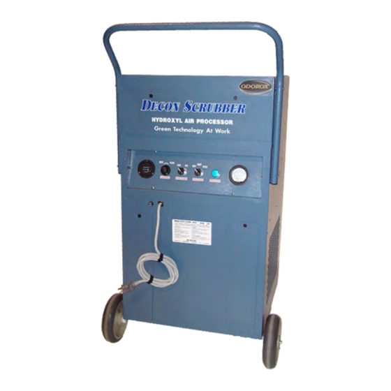
- Page 1 Decon Scrubber Owner’s Manual Serial # ____________________ REV0001111209...
-
Page 2: Table Of Contents
TABLE OF CONTENTS Warning Operating the Decon Scrubber System Placement Caring for your Decon Scrubber Cleaning Instructions Optic Replacement Instructions Filter Replacement Instructions Specification and Warranty... -
Page 3: Warning
ENGLISH IMPORTANT SAFETY INFORMATION. READ ALL INSTRUCTIONS BEFORE USING. WARNING! Use this Hydroxyl Generator only for its intended purpose as described in this Owner’s Manual. to manufacturer or authorized repair facility for PLEASE READ AND SAVE examination, electrical or mechanical adjustment, THESE IMPORTANT SAFETY or repair. -
Page 4: Operating The Decon Scrubber
OPERATING THE DECON SCRUBBER The Control Panel 1) Main Power Switch – Turns power on to the Decon Scrubber. This switch must be in the “ON” position before trying to control the “FAN SPEED” or “PROCESSOR” switches. 2) Fan Speed Switch – Controls the speed of the fan and airflow through the system. - Page 5 FAN SPEED The Decon Scrubber is equipped with an air mover fan, which runs between 750 and 1500 cubic feet per minute. In order for the fan to turn on, the MAIN POWER switch must be in the ON position. Once the MAIN POWER switch is on, the fan speed can be controlled by rotating the FAN SPEED knob clockwise to increase the speed, or counter clockwise to decrease the speed.
-
Page 6: System Placement
ENGLISH SYSTEM PLACEMENT The manner in which you position the Decon Scrubber can have a big impact on its efficiency. You may have to experiment a little to find the best position for the system. You should position the system as per (Figure 1) for efficient decontami- nation. -
Page 7: Caring For Your Decon Scrubber
Interior The interior of the Decon Scrubber can be cleaned in the same manner as the exterior. OPTIC CLEANING Cleaning of the optics is recommended to maintain peak processing efficiency. Fingerprints, smudg- es, dirt, dust particles, etc. -
Page 8: Cleaning Instructions
ENGLISH CLEANING INSTRUCTIONS Step 1 - Turn “Main Power” switch to the “OFF” position Step 2 - Unplug power cord from 120 volt receptacle * NOTE - Use caution to pull from the plug and not from the cord Step 3 - Remove 4 inch and 2 inch filters (refer to filter replacement instructions) * CAUTION - Use clean leather gloves and eye protection when handling the optics in this unit Step 4 - Remove optics (refer to optic replacement instructions) Step 5 - Remove top panel by removing Phillips screws and gently pulling off panel... -
Page 9: Optic Replacement Instructions
* NOTE - Use caution to pull from the plug and not from the cord Step 3 - Gently lay Decon Scrubber down on the front side (side opposite handle) * NOTE - Ensure unit is set on a stable non-scratch surface... - Page 10 ENGLISH OPTIC REPLACEMENT INSTRUCTIONS Step 6 - Disconnect optic to be replaced by holding the optic base with one hand, and the optic har- ness connector with the other hand. Gently ‘wiggle’ connector while pulling from the optic base. Step 7 - Gently pull optic from three optic supports * Note - Do not put any pressure on the side of the optic without support Step 8 - Gently install new optic by pressing into the three optic supports * Note - Portion of optic containing the connector must be side pressed into the optic supports...
- Page 11 ENGLISH OPTIC REPLACEMENT INSTRUCTIONS Step 9 - Re-connect optic connector * Optic connector is keyed and will only connect in one direction. If unable to connect optic base with optic connector, rotate connector 180º and try again. Step 10 - Re-install bottom panel with Phillips (Star) screws previously removed...
-
Page 12: Filter Replacement Instructions
ENGLISH FILTER REPLACEMENT INSTRUCTIONS Main 4 Inch Filter Step 1 - Turn “Main Power” switch to the “OFF” position Step 2 - Unplug power cord from 120 volt receptacle * NOTE - Use caution to pull from the plug and not from the cord Step 3 - Remove the two top Phillips (Star) screws (or push and turn the phillips quarter turn fastener counter clockwise) on the main filter door Step 4 - Swing top of main filter door down... - Page 13 ENGLISH FILTER REPLACEMENT INSTRUCTIONS 2 Inch Pre-Filters Step 1 - Turn “Main Power” switch to the “OFF” position Step 2 - Unplug power cord from 120 volt receptacle * NOTE - Use caution to pull from the plug and not from the cord Step 3 - Remove the Phillips (Star) screw located at the top of the pre-filter door (or push and turn the phillips (Star) quarter turn fastener counter clockwise) Step 4 - Pull the top of the pre-filter door out and lift off...
- Page 14 ENGLISH FILTER REPLACEMENT INSTRUCTIONS Step 8 - Keep pressure on the bottom of the door while the top gets pushed in place Step 9 - Reinstall Phillips (Star) screw previously removed (or push and turn the phillips (Star) quarter turn fastener clockwise)
-
Page 15: Specification And Warranty
Meter: 1/10 Quartz Hour Meter WARRANTY HGI Industries, Inc. warrants that this Decon Scrubber (excluding spare parts and consumables) shall be free from defects in workmanship or materials for a period of one (1) year from the delivery thereof to the customer. - Page 16 Odorox® product, please contact your local Odorox® distributor. Odorox® Hydroxyl Generators are proudly manufactured in the USA. Copyright © 2011, HGI Industries Incorporated Odorox and Boss XL3 are trademarks or registered trademarks of HGI Industries Incorporated, Boynton Beach, Florida USA.
Need help?
Do you have a question about the Decon and is the answer not in the manual?
Questions and answers