Table of Contents
Advertisement
Quick Links
EUROPEAN COMMUNITY DIRECTIVES
This equipment meets all requirements of European Community Directives for Low Voltage
(72/23/EEC), General Safety (92/59/EEC), and Electromagnetic Compatibility (89/336/EEC).
st
1
Issue
User Guide
DG551C
11/06
CONTROLLI
16010 SANT'OLCESE Genova – Italy
Tel. +39 01073061
ISO9000
Fax +39 0107306870/871
info@controlli.org
E-mail
1
Web www.controlli.org
DMP054E
Advertisement
Table of Contents

Summary of Contents for Controlli DG551C
-
Page 1: User Guide
User Guide DG551C EUROPEAN COMMUNITY DIRECTIVES This equipment meets all requirements of European Community Directives for Low Voltage (72/23/EEC), General Safety (92/59/EEC), and Electromagnetic Compatibility (89/336/EEC). Issue 11/06 DMP054E CONTROLLI 16010 SANT’OLCESE Genova – Italy Tel. +39 01073061 ISO9000 Fax +39 0107306870/871 info@controlli.org... -
Page 2: Table Of Contents
DG510) ................15 ANEL MOUNT ONTROLLER IRING ..........................15 NSTALLATION HECKLIST DG551C APPLICATIONS..........................16 LCD DISPLAY............................... 22 LCD DISPLAY............................... 23 LCD DISPLAY............................... 24 LCD DISPLAY............................... 25 MENU OPTIONS DESCRIPTION ......................25 Sat.+ Amb. 1-5 ............................26 Amb.+ PreR. 6-7 ............................27 Heat Loop.............................. - Page 3 Manual Shutdown............................. 33 Holidays ..............................33 Issue 11/06 DMP054E...
-
Page 4: Introduction
Introduction The DG551C controller • allows the complete automatic control and management of the air-conditioning plant type chosen among the various applications (see, further for a list) configured and existing in the controller. In order to enable the required application, it is sufficient to carry out the controller electrical connections according to the relevant scheme and to follow the instructions in the present manual. -
Page 5: Installation
Ex. 2 Programme: Monday to Friday on 08, off 12, on 13,30 on 17, Saturday on 08, off 13, Sunday Monday, Tuesday, Wednesday, 08:00 12:00 13:30 17:00 Thursday, Friday Saturday 08:00 13:00 13.00 13.00 Sunday 00:00 00:00 00:00 00:00 In order to edit the set values of the required variables or, simply to monitor values of the variables and sets, refer to the Menu description below. -
Page 6: Precautions
Precautions WARNINGS – ELECTRICAL SHOCK HAZARD! DISCONNECT POWER BEFORE INSTALLING OR REMOVING THE COVER. General Precautions • Follow Static precautions when installing this equipment. • Use copper conductors that are suitable for 75°C. • Make all connections according to electrical wiring diagram, national and local electrical codes. Static Precautions Static charges damage electronic components. -
Page 7: Wall Or Din Rail Mounting
Wall or DIN rail mounting 1. Select mounting location. Allow minimum 50mm clearance around controller. 2. Do the following to mount controller on a panel without DIN rail: Loosen two screws securing terminal cover and remove cover. Lift wall mounting bracket clip (located on top back of controller). Using a No. -
Page 8: Lcd Panel Mounting Using Dg510 Kit
LCD Panel Mounting using DG510 Kit Communication only for networks with more than one controller DG550 can operate as a stand-alone device or on larger installations connected to a NCP communication network. Issue 11/06 DMP054E... -
Page 9: Addressing
Addressing The default address for a standalone DG550 Controller is “Subnet 1 Node 2”, i.e. switch 2 set to Each DG550 Controller has a unique address for communicating with a PC or modem. a) Ensure the controller is not powered up. b) Set switches 1 to 7 to the appropriate ON/OFF position to enable the binary address. -
Page 10: Dg550 Terminal Connections
DG550 Terminal Connections Wiring Routing Rules The following table shows cable types that can be routed together: a Comms must always be screened b Screen UI c Screen DI d Screen AO Issue 11/06 DMP054E... -
Page 11: Ncp Network Wiring
NCP Network Wiring Controllers may be networked to either a 'main LAN' by an MN50-MI-NCP or to a 'sub-LAN' using a MicroNet Touch Screen. The recommended cable for NCP networks is Belden 9502 dual twisted-pair screened cable with full opto-isolation in areas of high electrical noise. Connect the network to the controller, as shown in the following diagram. - Page 12 I/O Wiring I/O connections include 10 configurable universal inputs (UIs), 2 digital inputs (DI), 6 digital outputs (Line relay), and 4 analogue outputs (AO). The DOs are line relays for switching up to 230Vac, 5A loads. Four analogue outputs provide 0 to 10V. WARNINGS –...
-
Page 13: Digital Uis
Digital UIs Note: Only dry (voltage free) contacts can be monitored. Maximum count frequency is once every two seconds. 1.Connect one wire from field contact to desired input terminal (8, 9, 10, 11, 12, 13, 14, 15, 16 or 17). Polarity is not important. 2.Connect other wire to one UI common (COM) terminal (31, 32, 33, 34, 35, 36, 37, 38, 39 or 40). -
Page 14: Power Supply Wiring
Power Supply Wiring 24Vac Power Wiring 1.Ensure that the controller GND terminal is connected to Earth before connecting the power wiring to the controller. 2.Connect power ground wiring to terminal 24 (GND). 3.Connect power 24Vac wiring to terminal 1 (24V~). Notes: 1.This product contains a non-isolated half-wave rectifier power supply and must not be powered by transformers used to power other devices containing non-isolated full-wave rectifier... -
Page 15: Panel Mount Controller/Lcd Wiring (Kit Dg510)
Panel mount Controller/LCD Wiring (Kit DG510) It consists of a separate LCD and Base Unit. The two units should be wired together in the following manner. Installation Checklist 1. If controller is part of a NCP network, verify network wiring between controller and other devices is effected according to job wiring diagram and national and local electrical codes. -
Page 16: Dg551C Applications
DG551C APPLICATIONS Damper Pressure switch Anti frost 1 : P r i m a r y a i r . 2 c o i l s ( h e a t i n g , c o o l i n g ) , h u m i d i f i c a t i o n . C o m p e n s a t e d o r s e t p o i n t adjustment of the dew point. - Page 17 Anti Damper frost Pressure switch 2: 1+ 2-pipe fan-coil water production. Compensated or set point control of hot water in winter; compensated or set point control of cold water through external summer/winter switch. The inputs marked by ° are optional. The stroke end, if not used, must be short-circuited, in order to have a “On”...
- Page 18 Anti Damper frost Pressure switch 3: 1+ 4-pipe fan-coil water production. Compensated or set point control of hot water in winter; compensated or set point control of cold water. The inputs marked by ° are optional. The stroke end, if not used, must be short- circuited, in order to have a “On”...
- Page 19 Anti Damper frost Pressure switch 4: Primary air. 3 coils (heating,cooling, post-heating) humidification. Compensated or set point control of dew point and supply temperature. On/Off humidifier, anti-frost thermostat. The inputs marked by ° are optional. The stroke end, if not used, must be short-circuited, in order to have a “On”...
- Page 20 Anti Damper frost Pressure switch 5: 4 + 2-pipe fan-coil water production. Compensated or set point control of hot water in winter; compensated or set point control of cold water through external summer/winter switch. The inputs marked by ° are optional. The stroke end, if not used, must be short- circuited, in order to have a “On”...
- Page 21 Anti Damper frost Pressure switch 6: AHU outside air. Heating, cooling, humidification. Compensated or set point control of room temperature. Supply limit. On/Off humidifier. Anti-frost thermostat. Room temperature manual control (optional). The inputs marked by ° are optional. The stroke end, if not used, must be short-circuited, in order to have a “On”...
- Page 22 Anti Damper frost Pressure switch 7: AHU outside air. Pre-heating, heating, cooling, humidification.C o m p e n s a t e d o r s e t p o i n t c o n t r o l o f p r e - h e a t i n g a n d r o o m t e m p e r a t u r e . O n / O f f h u m i d i f i e r . A n t i - f r o s t thermostat.
-
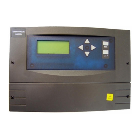
Page 23: Lcd Display
8: 2-pipe fan-coil water production. Compensated or set point control of hot water in winter; compensated or set point control of cold water through external summer/winter switch. The inputs marked by ° are optional. Issue 11/06 DMP054E... -
Page 24: Lcd Display
9: 4-pipe fan-coil water production. Compensated or set point control of hot water in winter; compensated or set point control of cold water. The inputs marked by ° are optional. Issue 11/06 DMP054E... -
Page 25: Lcd Display
LCD DISPLAY It allows displaying and/or editing the controller parameters, inputs and outputs. Menu Options Description NOTE: The default proportional band of the loop is = 15K. In case the loop controls on a room or return sensor, it is advisable to edit the proportional band = 2K. Out Temp 1 It displays outside temperature. -
Page 26: Sat.+ Amb. 1-5
Sat.+ Amb. 1-5 Select this menu for application from 1 to 5 – primary air management with eventual post-heating. Supply T 7 It displays supply temperature. Fixed SP 8 Value of the fixed (editable) SP for saturation temperature; it is on only if the outside sensor is not connected. -
Page 27: Amb.+ Prer. 6-7
outside t. room SP It is possible to edit and/or add values to the curve. In case it is necessary to delete already existing value pairs, just set a room t. value equal to the preceding one in the table. Example: outside t. - Page 28 Example: outside t. Room SP outside t. Room SP Amb. SP 18 Actual operating set point for HC and CC coils (read-only). Preh. T. 19 It displays pre-heating temperature. Read-only. Fixed SP 20 Value of the fixed (editable) SP for pre-heating temperature; it is on only if the outside sensor is not connected.
-
Page 29: Heat Loop
Preh. SP 22 Actual operating set point for pre-heating coil (read-only). Heat Loop Select this menu to display and/or edit the values related to the heating coil B1. Opening 23 It displays the valve opening percentage (read-only). P. Band 24 It displays the loop proportional band (read/write). -
Page 30: Fan Coil
Limit ? 35 This option can be used only with application number 6. If it is set to On, it enables the minimum loop management on supply. Default value: off Min. SP 36 This option can be used only with application number 6. Minimum limit (read/write). Default value 15°C. -
Page 31: Heating Loop
Heat SP 44 Actual operating set point for heating loop (read-only). Cool T. 45 It displays the cold fluid temperature. Read-only. Fixed SP 46 Value of the fixed (editable) SP for cold fluid temperature; it is on only if the outside sensor is not connected. -
Page 32: Cooling Loop
Test? 52 If it is set to On, it overrides the valve outlet at 100%, disabling the coil control. Set it back to Off at the end of the test phase. Cooling Loop Select this menu for menu to display and/or edit the data related to the fan coil cold fluid distribution. -
Page 33: Manual Override
Manual Override Select this menu to set and/or display the data related to manual start. Such function allows starting the plant even outside the normal operating time and during holidays. It is disabled only in case Manual Off is active. Remote 65 It displays the status of the manual start external switch. - Page 34 Issue 11/06 DMP054E...
- Page 35 Issue 11/06 DMP054E...
Need help?
Do you have a question about the DG551C and is the answer not in the manual?
Questions and answers