
Summary of Contents for L3 comminications ProTec
- Page 1 ProTec AUTOMATIC IDENTIFICATION SYSTEM HARDWARE INSTALLATION AND OPERATION MANUAL communications AIS PART NUMBER AISA1000--00 Rev. 02 July 29/03 P/N: 165M0014--00...
- Page 2 Aviation Recorders Marine Systems AIS Hardware I&O Manual 165M0014- -00 Rev. 02 July 29/03 The AIS products/software are being exported from the United States in accordance with the Export Adminis- tration Regulations ECCN 4D994, No License Re- quired. Diversion contrary to U.S. law is prohibited. In accordance with U.S.
-
Page 3: General 1
Aviation Recorders Marine Systems GENERAL This product and related documentation must be reviewed for familiarization with safety markings and instructions before operation. This board was constructed in an ESD (electro–static discharge) protected environment. This is because most of the semiconductor devices used in this board are susceptible to damage by static discharge. -
Page 4: References 1
Aviation Recorders Marine Systems RETURN MATERIAL POLICY Components and spare parts purchased from L--3 that are discrepant for any of the following reasons may be re- turned immediately provided the extended value of the parts are in excess of $100.00. Overshipments Quantity of parts received in excess of quantity specified on purchase order. - Page 5 Aviation Recorders Marine Systems RETURN OF MATERIAL UNDER WARRANTY Material should be returned to the following address: L--3 COMMUNICATIONS CORPORATION AVIATION RECORDERS DIVISION 6000 E. Fruitville Road Sarasota, FL 34232 Attn: WARRANTY RETURNS For returning overseas shipments, the following customs broker must be used: L--3 COMMUNICATIONS CORPORATION AVIATION RECORDERS DIVISION c/o A.J.
- Page 6 Aviation Recorders Marine Systems THIS PAGE IS INTENTIONALLY LEFT BLANK. Automatic Identification System Rev. 02 Page vi July 29/03...
-
Page 7: Table Of Contents
AUTOMATIC IDENTIFICATION SYSTEM SUBJECT/DESCRIPTION PAGE SECTION 1 - - ProTec AIS Introduction 1.1. General .............. -
Page 8: Automatic Identification System
(Continued) SUBJECT/DESCRIPTION PAGE SECTION 2 - - ProTec AIS Operation 2.1. Operation .............. - Page 9 Aviation Recorders Marine Systems LIST OF FIGURES FIGURE TITLE PAGE Figure 1--1. AIS Transponder ........... 1--6 Figure 2--1.
- Page 10 Aviation Recorders Marine Systems LIST OF TABLES TABLE TITLE PAGE Table 1--1. AIS Parts List ............1--9 Table 1--2.
- Page 11 Aviation Recorders Marine Systems SECTION 1 ProTec AUTOMATIC IDENTIFICATION SYSTEM (AIS) INTRODUCTION Automatic Identification System Rev. 02 Page 1--1 July 29/03...
- Page 12 Aviation Recorders Marine Systems THIS PAGE IS INTENTIONALLY LEFT BLANK. Automatic Identification System Rev. 02 Page 1--2 July 29/03...
-
Page 13: Section 1 - - Protec Ais Introduction
SOTDMA controllers, the L--3 ProTec provides a cost--effective AIS solution which will meet the needs of any vessel required to carry AIS. The compact, single--box design allows the L--3 ProTec to be easily incorporated into any bridge layout thus simplifying installation and cabling requirements. -
Page 14: References
Attn: Repair Department Tel: (941) 377--5558 Fax #: (941) 377--5585 CAUTION: THE L- -3 ProTec CIRCUIT BOARDS ARE SUSCEPTIBLE TO ELECTROSTATIC DESTRUCTION (ESD). PRIOR TO HANDLING PWAs, ENSURE PROPER PERSONNEL GROUNDING TECH- NIQUES ARE USED. ENSURE THAT CARDS ARE PLACED INTO STATIC SHIELDING CONDUCTIVE BAGS WHEN HANDLING OR STORING. -
Page 15: Acronyms
Aviation Recorders Marine Systems 1.1.3. Acronyms Addressed Binary Message Ackowledgement Message AIS Channel Assigment Ackowledgement Message Broadcast Binary Message Course Over Ground DGPS Differential Global Positiioning System Global Positioning Fix Data Geographic Position, Latitude/Longitude Global Positiioning System GPS DOP and Active Satellites GPS Satellites in View Heading, Deviation &... -
Page 16: Technical Specifications
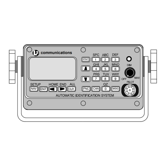
Aviation Recorders Marine Systems communications NOTE: 1. Front Panel Mating Connectors Pilot Port -- L3 PN: 063--98--02113 TYCO PN: 206485--1 Figure 1- -1. AIS Transponder 1.2. Technical Specifications Standards IMO MSC.74(69) Annex 3, IEC 61993--2, ITU.R.M.1371--1 Ship reporting capacity 2250 reports per minute, 4500 reports per minute on two channels TDMA Transmitter TX Frequency: 156.025 MHz -- 162.025 MHz, manual/automatic setting... - Page 17 Aviation Recorders Marine Systems TDMA Receiver RX Frequency: 156.025 MHz -- 162.025 MHz, 2 channels RX1: Default CH87B (161.975 MHz), manual/automatic setting RX2: Default CH88B (162.025 MHz), manual/automatic setting Channel Spacing: 25 kHz and 12.5 kHz DSC Receiver RX Frequency: CH70 (156.525 MHz) Internal GPS Receiver 12 Channel, UTC Synchronization Jitter (time between slot start and transmitter on):...
-
Page 18: Ais Description
1.3.2. Integral Minimum Keyboard Display (MKD) In line with the compact design, the L--3 ProTec is a single--box design incorporating an integral MKD which is fully IMO compliant. The interface includes a of 2.58” L (6.5 cm) x 1.16” H (2.9 cm) (160 x 64 Dots) backlit LCD screen for displaying alphanu- meric text and a multifunction keypad. -
Page 19: Equipment List
Aviation Recorders Marine Systems 1.3.5. Equipment List The Standard AIS Installation Kit includes the following equipment: Transponder Unit with Trunion OR Flush Mount IEC NMEA Data Cable Terminal Block (for data interface) Power Cable Installation Manual and parts kit In order to complete the installation, the following items will be required. GPS Antenna with coaxial cable VHF Antenna with coaxial cable Gyro Interface (if gyro output is not NMEA) -
Page 20: Operational Modes
1.3.6.1 Autonomous and Continuous This is the default mode. The ProTec AIS will determine its own schedule for trans- mission of position and identification and will automatically resolve scheduling con- flicts with other stations using the Self Organized Time Division Multiple Access (SOTDMA) methodology. -
Page 21: Dsc Functionality
DSC Functionality The Assigned and Polled operational modes are activated through a DSC message transmitted by the competent authority. In order to provide for this, the ProTec AIS contains a dedicated DSC receiver that is tuned to channel 70. DSC messages... -
Page 22: Ais Frequencies
Aviation Recorders Marine Systems Dimensions of ship -- to nearest meter. Location on ship where reference point for position reports is located. Type of position fixing device -- various options from differential GPS to undefined. Draught of ship -- 1/10 meter to 25.5 meters [note “air--draught” is not pro- vided]. -
Page 23: Interface Description
Aviation Recorders Marine Systems 1.4. Interface Description 1.4.1. Pilot Systems Input Data and Formats The input data and formats are shown in Table 1--2, and the details of the sentences can be found in IEC 61162--1. Table 1- - 2. Pilot System High- - Speed Input Data Formats Data IEC 61162- -1 Sentences Normal Access - - Parameter Entry... -
Page 24: Pilot Systems Output Data And Formats
Aviation Recorders Marine Systems 1.4.2. Pilot Systems Output Data and Formats The output data and formats are shown in Table 1--3, and the details of the sen- tences can be found in IEC 61162--1. Table 1- -3. Pilot System High- -Speed Output Data Formats Data IEC 61162- -1 Sentences Prepared by AIS Transponder... -
Page 25: Long Range Equipment Interface
Long Range communication port. The Officer of the Watch must approve the Long Range replay when in MANUAL mode, by a means of pressing a keyboard button on the L--3 ProTec before the re- ply is performed. -
Page 26: Long Range Output Data And Formats
Aviation Recorders Marine Systems Table 1- - 4. Long Range Input Data and Formats Data IEC 61162- -1 Sentences Long Range Interrogation LRI -- Long Range Interrogation Type of request: -- Geographic area request -- AIS transponder request Long Range Function identification LRF -- Long Range Function Requestor MMSI and Name Request for:... -
Page 27: Table 1--5. Long Range Output Data And Formats
Aviation Recorders Marine Systems The LR2 sentence contains the information items requested by the “B, C, E, and F” function identification characters in the LRF sentence. The LR3 sentence contains the information items requested by the “I, O, P, U, and W” function identification characters in the LRF sentence. Table 1- - 5. -
Page 28: Sensor Input Data And Formats
Aviation Recorders Marine Systems 1.4.7. Sensor Input Data and Formats The L--3 ProTec Shipborne Class A Transponder supports input data sentences from various ship sensors, refer to Table 1--6. Table 1- - 6. Sensor Input Data and Formats Sensor Data... -
Page 29: Operation 2
Aviation Recorders Marine Systems SECTION 2 ProTec AUTOMATIC IDENTIFICATION SYSTEM (AIS) OPERATION Automatic Identification System Rev. 02 Page 2--1 July 29/03... - Page 30 Aviation Recorders Marine Systems THIS PAGE IS INTENTIONALLY LEFT BLANK. Automatic Identification System Rev. 02 Page 2--2 July 29/03...
-
Page 31: Operation
2.1.1. Minimum Keyboard Display The L--3 ProTec includes and integral MKD which is fully IMO compliant. It is recom- ended that the MKD should not act as the primary display due to limitations in data presentation options. It should be used for configuration of the hardware and entry of vessel and voyage specific data, which is required infrequently. -
Page 32: Power/Dim Control
Aviation Recorders Marine Systems 2.1.1.1 Power/Dim Control A single control knob controls both the on/off function and backlighting level for the LCD. To turn the unit ’On’, rotate the knob clockwise. To turn unit ’Off’ rotate counter- clockwise fully. The degree of rotation determines the brightness of the LCD back- light and rotation to the right will dim the backlighting. - Page 33 Aviation Recorders Marine Systems Vessel (default) screen, the Left or Right Arrow Keys will allow the user to toggle between the Ship Name display and the MMSI screen. (The MMSI screen will always be displayed for a vessel if the ship name is not known. Function Key Used as the initial key in a key sequence to access the various secondary functions of the interface.
-
Page 34: Data Display Screens
Aviation Recorders Marine Systems FNC--ENT Own Ship display (NAV Key will also bring up this screen if already showing the Closest Ves- sel display.) 2.1.3. Data Display Screens The AIS interface consists of the following display screens each of which is ac- cessed using the defined key sequence. -
Page 35: Figure 2--3. Own Ship Data Display
Aviation Recorders Marine Systems Displays ID, Range, and Bearing of nearest three (3) vessels sorted by range, clos- est first. This is the default display screen and accessed from anywhere within the menu system by pressing the NAV key. As the default screen, it will display automat- ically after 10 seconds of inactivity on any other screen. -
Page 36: Data Entry Screens
Aviation Recorders Marine Systems Latitude Longitude Vessel Heading in degrees true from Gyrocompass Rate of turn in degrees/sec (-- denotes port, + denotes stbd) Course Over Ground in degrees true from dGPS Speed Over Ground in knots from dGPS 2.1.4. Data Entry Screens The AIS interface provides the following three data entry screens for completing in- put of required vessel and voyage data and for modifying the administrator pass-... -
Page 37: Vessel Data Setup
Aviation Recorders Marine Systems NOTE: Figure 2- -4 shows the System Configuration and Status menu screen as it appears as the user initially enters this menu. Not shown is the Change Password option. S y s t o n f a n d n -- n g s... -
Page 38: Table 2--1. Vessel Type Codes
Aviation Recorders Marine Systems Table 2- - 1. Vessel Type Codes Special Crafts Other Ships First Digit Second Digit 50Pilot Boats 6 Passenger Ships 0 All ships of this type 51Search and Rescue Vessels 7 Cargo Ships 1 Carrying DG HS or MP IMO hazard or polluant 52Tugs 8 Tankers... -
Page 39: Channel Management
The L--3 ProTec Transponder will hold up to eight different channel configura- tions. The user can set these different configurations at the initial setup; however, the L--3 ProTec Transponder will acquire the data for a new region once it has en- tered the region. -
Page 40: Antenna Position
Aviation Recorders Marine Systems A c t X ° X ° X ° X ° -- -- -- -- -- -- -- -- ¬ ® Figure 2- -6. Channel Management Settings Screen 2.1.4.3 Antenna Position This setup provides for data entry of location of the antenna for each of the GPS an- tennas required for the system. -
Page 41: Text Messaging
Aviation Recorders Marine Systems All dimensions defined below are entered in meters. Distance in meters from Forward Perpendicular (FP) Distance in meters from After Perpendicular (AP) Distance in meters inboard from port side Distance in meters inboard from starboard side Figure 2- -8. -
Page 42: Figure 2--9. Safety Text Message
Aviation Recorders Marine Systems To broadcast a message, perform the following: Press MSG key. Verify that they MMSI number is all zeros. If the MMSI is not all zeros, press the down arrow key until the MMSI is high- lighted. Press the ENT key, and enter all zeros for the MMSI number. -
Page 43: Password Entry
Aviation Recorders Marine Systems * * * S a f e v i 0 0 0 0 0 0 0 0 ¬ ® e v . Figure 2- -10. Safety Text Review Screen 2.1.4.5 Password Entry Passwords allow the user to change the information contained within the AIS Trans- ponder. -
Page 44: Change Password
Aviation Recorders Marine Systems To log on perform the following: Press the FNC key. Press the Setup key. The System Configuration screen will appear. Using the down Arrow key, select Logon, and press the ENT key. The System Password Entry screen will appear. Press the ENT key, and enter the password, and press the ENT again. -
Page 45: System Alert Screen
Figure 2- - 13. System Alert Screen 2.1.4.8 Alarm Status The ProTec AIS unit does not support a “General Failure” alarm since all detected failures are reported with an explicit discrete alarm message. To review Safety Text Messages that have been received, perform the following: Press the FNC key. -
Page 46: Down--Time Log
Aviation Recorders Marine Systems Using the down Arrow key, select “View Alarm Status”, and press the ENT key. Use the down left and right arrows to view previous or next messages respec- tively. Press the ESC key to return to the System Configuration screen. Figure 2- - 14. -
Page 47: Installation
Aviation Recorders Marine Systems SECTION 3 ProTec AUTOMATIC IDENTIFICATION SYSTEM (AIS) INSTALLATION Automatic Identification System Rev. 02 Page 3--1 July 29/03... - Page 48 Aviation Recorders Marine Systems THIS PAGE IS INTENTIONALLY LEFT BLANK. Automatic Identification System Rev. 02 Page 3--2 July 29/03...
-
Page 49: Figure 3--1. Ais Transponder Interconnection Diagram
ProTec AIS Installation 3.1. Installation The L--3 ProTec Transponder has been designed for easy installation into any exist- ing bridge layout. Figure 3--1 gives a general representation of the system layout. Installation can be broken down into 5 distinct operations as follows:... - Page 50 3.1.1. Transponder The L--3 ProTec is a single box design which is easily installed into any existing bridge layout. The compact design requires minimal clearance (refer to Figure 3--2 and Figure 3--3) and can be mounted in a trunion bracket or mounted flush using the available flush--mount bracket.
-
Page 51: Figure 3--2. Ais Transponder O&D Drawing With Trunion Bracket
Aviation Recorders Marine Systems 7.23 in. ¦ .12 184 mm ¦ 3 31.75 mm 1.25 in. 6.87 in. ¦ .12 7.81 in. ¦ .12 31.75 mm 6.40 in. ¦ .06 1.25 in. 198 mm 174 mm 163 mm ¦ 3 ¦... -
Page 52: Figure 3--3. Ais Transponder O&D Drawing
Aviation Recorders Marine Systems 7.23 in. ¦ .12 184 mm ¦ 3 6.40 ¦ .06 163 mm ¦ 1.5 0.625 15.875 mm 83 mm 3.14 in. ¦ 1.5 2.937 in. ¦ .06 ¦ .06 3.28 in. 80 mm ¦ .06 75 mm ¦... -
Page 53: Figure 3--4. Ais Transponder Power Cable
Aviation Recorders Marine Systems 25 mm ¦ 6 mm 1.8 m ¦ 0.05 m Green ID MARK Black White Cable End Signal Table for “Cable Assembly, Power/BIIT, External” Line Color Name Description Function Power Black B(--) Battery, negative Power return ---- B(+) Battery, positive... -
Page 54: Figure 3--5. Pilot Port Cable
Aviation Recorders Marine Systems SHIELD WHT TXA BLK TXB GRN RXA BLK RXB Reserved Do Not Connect Reserved Do Not Connect Pilot Port Connector Reserved Do Not Connect Reserved Do Not Connect 72 in. ¦ 2 1.8 m ¦ 0.05 m Figure 3- -5. -
Page 55: Table 3--1. Data Channels
AIS is referenced with the L--3 ProTec considered the “MASTER” in that transmit data is OUTPUT from the L--3 ProTec, and receive data is INPUT to the L--3 ProTec. All channels are isolated with individual shielded twisted pair cables. -
Page 56: Figure 3--6. Ais Transponder Iec Data Cable
Aviation Recorders Marine Systems 3.1.2.2 Data Cable Each transponder will come shipped with an 100 inches long IEC data cable (P/N 024--M0088--01) terminated at one end by a J4 connector. (Refer to Figure 3--6, Figure 3--7 and Figure 3--8.) The IEC data cable is shielded and contains three smaller diameter cables, each of which is also shielded. -
Page 57: Figure 3--7. Iec Data Cable Interconnect Diagram
Aviation Recorders Marine Systems DB31 IEC CABLE IEC INTF MOD OPTIONAL TERMINATION ISO_GND1 OPTO_ISO RX_A RS422 TX_A AND TX_B DB9 MALE RX_B CHANNEL 1 RXD_CH1 ISO_GND2 OPTO_ISO RX_A RS422 TX_A AND TX_B DB9 MALE CHANNEL 2 RX_B RXD_CH2 ISO_GND3 OPTO_ISO RX_A RS422 TX_A AND TX_B DB9 MALE... -
Page 58: Figure 3--8. Iec Data Cable External Wiring Diagram
Aviation Recorders Marine Systems CABLE GROUP 1 CABLE GROUP 2 CABLE GROUP 3 12- -24 VDC Figure 3- - 8. IEC Data Cable External Wiring Diagram Automatic Identification System Rev. 02 Page 3--12 July 29/03... -
Page 59: Terminal Block 3
Aviation Recorders Marine Systems 3.1.2.3 Terminal Block Each Transponder will come shipped with a 31 pin terminal block. A terminal block is the preferred installation method for completing the data interface (NMEA) because data output from a ship sensor ( dGPS, ROT, Gyro) may not subscribe to a standard pinout definition. -
Page 60: Table 3--2. Iec Cable And Junction Box Pinouts
Aviation Recorders Marine Systems NOTE: Each shielded twisted pair of wires is shielded as well by metallic shielding and a drain wire connected to this shield- ing is to be connected in accordance with Table 3- -2. Table 3- - 2. IEC Cable and Junction Box Pinouts Cable Wire Color IEC Pin... -
Page 61: Installing The Vhf Antenna 3
Aviation Recorders Marine Systems 3.1.3. Installing the VHF Antenna Installation of a VHF antenna is as important to reliable communications as the transceiver itself. It is recommended that a high quality antenna be purchased from an established source and that all manufactures instructions be followed with partic- ular attention to cable routing and connector installation. -
Page 62: Installing The Gps Antenna 3
Aviation Recorders Marine Systems 3.1.4. Installing the GPS Antenna The correct installation of a GPS antenna is crucial to the operation of the trans- ponder because the internal transmission synchronization relies on the accuracy of the time signal obtained from the GPS. It is recommended that a high quality GPS antenna be purchased from an established source and that all manufactures instruc- tions be followed with particular attention to cable routing and connector installation. -
Page 63: Figure 3--9. Ais Transponder Antenna Diagram
Aviation Recorders Marine Systems VHF Antenna Mini VHF Connector 20 ft. 50 ft. 15 m PL259 RG8X Female Male GPS Antenna 70 ft. 21 m TNC Connector Female RJ223 TNC Connector Male Figure 3- -9. AIS Transponder Antenna Diagram Automatic Identification System Rev. -
Page 64: Figure 3--10. Ais Transponder Rear View
Aviation Recorders Marine Systems GPS ANTENNA VHF ANTENNA RAIL MOUNTED DECK MOUNTED TNC CONN 21 m 70’ RG59 COAX MALE TNC CONN 15 m MALE 50’ RG8X COAX PL 259 Mini VHF CONN Power Consumption: 10--32 vdc 12 watts nominal -- 50 watts max. OTHER NOTES: DGPS... -
Page 65: Figure 3--11. Ais Transponder Mkd
Aviation Recorders Marine Systems 3.1.5. PowerUp and Configuration At this stage you should have the following steps completed: Transponder installed and 10--32 Vdc power connected. VHF antenna installed and connected to transponder. GPS antenna installed and connected to transponder. IEC data cable installed and connected to transponder and terminal block. The next step in the installation of the AIS transponder involves setup and configura- tion. -
Page 66: Figure 3--12. System Configuration Screen
Aviation Recorders Marine Systems Enter Vessel Static Information and Voyage Information. Press FNC and then NAV to get to the System Configuration screen. S y s t o n f a n d n -- n g s Figure 3- - 12. System Configuration Screen Use DOWN ARROW key to scroll down to Vessel Data Setup. -
Page 67: Table 3--3. Vessel Type Codes
Aviation Recorders Marine Systems Csgn: Radio Callsign (maximum 7 characters) Type: Vessel Type (see codes listed in Table 3--3 below) Name: Vessel Name (maximum 20 characters) Dest: Name of next Destination (maximum 20 characters) ETA: Estimated Time of Arrival (MMDDHHMM UTC) Table 3- - 3. -
Page 68: Figure 3--14. Antenna Position
Aviation Recorders Marine Systems The following keyboard commands will allow you to navigate and complete the data entry requirements for this screen. Use the LEFT, RIGHT, UP, DOWN arrows to navigate between fields. Use the ENT key to select a field to enter. Use the alphanumeric keypad to enter the required data into the field. -
Page 69: Figure 3--15. Calculating Antenna Position
Aviation Recorders Marine Systems Figure 3- - 15. Calculating Antenna Position This completes the configuration requirements of the AIS. The next step involves checking the system linkup to ship’s dGPS and Gyro. To check these links you must enter the Own Ship Data screen of the interface. (10) Enter FNC and then ENT. - Page 70 Aviation Recorders Marine Systems Automatic Identification System Rev. 02 Page 3--24 July 29/03...
Need help?
Do you have a question about the ProTec and is the answer not in the manual?
Questions and answers