Table of Contents
Advertisement
Quick Links
Advertisement
Table of Contents

Summary of Contents for EtherCAT TMCM-1310
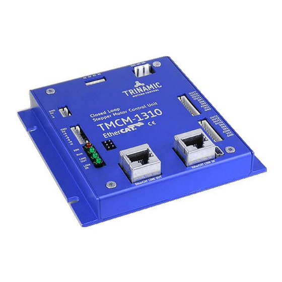
- Page 1 MODULE FOR STEPPER MOTORS MODULE Firmware Version V1.11 TMCL™ FIRMWARE MANUAL TMCM-1310 1-Axis Stepper Closed Loop Controller / Driver 3 A RMS / 48 V ABN and SSI Encoder Input 18 GPIOs USB, EtherCAT® TRINAMIC Motion Control GmbH & Co. KG Hamburg, Germany www.trinamic.com...
-
Page 2: Table Of Contents
TMCM-1310 TMCL Firmware V1.11 Manual (Rev. 1.16 / 2014-MAR-19) Table of Contents Features ................................... 4 Overview ..................................6 Communication via EtherCAT ........................... 7 SyncManager ................................. 7 3.1.1 Buffered Mode ..............................7 3.1.2 Mailbox Mode, used for TMCL-Applications ................... 8 EtherCAT Slave State Machine ......................... 9 EtherCAT Firmware Update .......................... - Page 3 TMCM-1310 TMCL Firmware V1.11 Manual (Rev. 1.16 / 2014-MAR-19) 6.8.21 RSUB (return from subroutine) ........................ 46 6.8.22 WAIT (wait for an event to occur) ......................47 6.8.23 STOP (stop TMCL program execution) ....................48 6.8.24 SCO (set coordinate) ........................... 49 6.8.25 GCO (get coordinate) ..........................
-
Page 4: Features
TMCM-1310 TMCL Firmware V1.11 Manual (Rev. 1.16 / 2014-MAR-19) Features The TMCM-1310 is a single axis stepper motor controller/driver standalone board with closed loop support. For communication an USB interface and EtherCAT®* are provided. The module supports motor currents up to 3A RMS and supply voltages up to 48V nominal. - Page 5 EATURES LOSED The TMCM-1310 is mainly designed to run 2-phase stepper motors in closed loop mode. It offers an automatic motor load adaption in positioning mode, velocity mode, and torque mode, which is based on encoder feedback and closed loop control software for analysis, error detection and error correction.
-
Page 6: Overview
TMCM-1310 TMCL Firmware V1.11 Manual (Rev. 1.16 / 2014-MAR-19) Overview The software running on the microprocessor of the TMCM-1310 consists of two parts, a boot loader and the firmware itself. Whereas the boot loader is installed during production and testing at TRINAMIC and remains untouched throughout the whole lifetime, the firmware can be updated by the user. -
Page 7: Communication Via Ethercat
The buffered mode is used for cyclic process data. Data transfer between EtherCAT master (PC etc.) und slave (TMCM-1310) is done using the dual port memory of the ET1100 EtherCAT-IC on the slave. The buffered mode allows writing and reading data simultaneously without interference. -
Page 8: Mailbox Mode, Used For Tmcl-Applications
The mailbox mode implements a handshake mechanism for data exchange, so that no data will be lost. Each side, EtherCAT master or local application will get access to the buffer only after the other side has finished its access. The mailbox mode only allows alternating reading and writing. This assures that all data from the producer will reach the consumer. -
Page 9: Ethercat Slave State Machine
EtherCAT Slave State Machine The EtherCAT slave state machine has four states, which are shown in Figure 3.4. After power ON the slave state machine is in the Init state. In this situation mailbox and process data communication is impossible. - Page 10 TMCM-1310 TMCL Firmware V1.11 Manual (Rev. 1.16 / 2014-MAR-19) State / state change Services Init No communication on application layer Master has access to the DL-information registers Init to Pre-Operational Master configures registers, at least: • DL address register •...
-
Page 11: Ethercat Firmware Update
TMCM-1310 TMCL Firmware V1.11 Manual (Rev. 1.16 / 2014-MAR-19) EtherCAT Firmware Update For firmware updates the EtherCAT state machine of the slave has to be switched to Bootstrap state. The file access over EtherCAT protocol (FoE) is used. HE TWO MAILBOXES FOR DATA TRANSFERS HAVE THE FOLLOWING PARAMETERS... - Page 12 TMCM-1310 TMCL Firmware V1.11 Manual (Rev. 1.16 / 2014-MAR-19) -> ATA INPUT BUFFER THER SLAVE MASTER DATA TRANSFER Data input buffer: Start-address: 4216(0x1078), length: first 44 bytes Start address End address Data type Data value / contents 0x1078 0x107B SIGNED32...
-
Page 13: Tmcl Mailbox
TMCM-1310 TMCL Firmware V1.11 Manual (Rev. 1.16 / 2014-MAR-19) TMCL Mailbox The TMCM-1310 slave module supports the TMCL protocol in direct mode. The communication follows a strict master-slave-relationship. Via the TMCL mailbox motor-parameters can be read and/or written. Binary Command Format Every command has a mnemonic and a binary representation. -
Page 14: Operation With Usb Interface
TMCM-1310 TMCL Firmware V1.11 Manual (Rev. 1.16 / 2014-MAR-19) Operation with USB Interface In direct mode and most cases the TMCL communication over USB follows a strict master/slave relationship. That is, a host computer (e.g. PC/PLC) acting as the interface bus master will send a command to the TMCL-1310. -
Page 15: Reply Format
TMCM-1310 TMCL Firmware V1.11 Manual (Rev. 1.16 / 2014-MAR-19) Reply Format Every time a command has been sent to a module, the module sends a reply. HE REPLY FORMAT FOR IS AS FOLLOWS Bytes Meaning Reply address Module address Status (e.g. 100 means “no error”) -
Page 16: The Ascii Interface
TMCM-1310 TMCL Firmware V1.11 Manual (Rev. 1.16 / 2014-MAR-19) The ASCII Interface There is also an ASCII interface that can be used to communicate with the module and to send some commands as text strings. The ASCII format can be used with the USB interface, only. -
Page 17: Configuring The Ascii Interface
TMCM-1310 TMCL Firmware V1.11 Manual (Rev. 1.16 / 2014-MAR-19) Configuring the ASCII Interface The module can be configured so that it starts up either in binary mode or in ASCII mode. Global parameter 67 is used for this purpose (please see also chapter 11.1). -
Page 18: Tmcl Commands
TMCM-1310 TMCL Firmware V1.11 Manual (Rev. 1.16 / 2014-MAR-19) TMCL Commands Motion Commands These commands control the motion of the motor. They are the most important commands and can be used in direct mode or in standalone mode. Mnemonic Command number... -
Page 19: Calculation Commands
TMCM-1310 TMCL Firmware V1.11 Manual (Rev. 1.16 / 2014-MAR-19) Calculation Commands These commands are intended to be used for calculations within TMCL applications. Although they could also be used in direct mode it does not make much sense to do so. -
Page 20: Interrupt Vectors
TMCM-1310 TMCL Firmware V1.11 Manual (Rev. 1.16 / 2014-MAR-19) 6.6.3 Interrupt Vectors The following table shows all interrupt vectors that can be used. Interrupt number Interrupt type Timer 0 Timer 1 Timer 2 Target position reached stallGuard2 Deviation Left stop switch... -
Page 21: Ascii Commands
TMCM-1310 TMCL Firmware V1.11 Manual (Rev. 1.16 / 2014-MAR-19) In the above example, the interrupt numbers are used directly. To make the program better readable use the provided include file Interrupts.inc. This file defines symbolic constants for all interrupt numbers which can be used in all interrupt commands. -
Page 22: Commands
TMCM-1310 TMCL Firmware V1.11 Manual (Rev. 1.16 / 2014-MAR-19) Commands The module specific commands are explained in more detail on the following pages. They are listed according to their command number. 6.8.1 ROR (rotate right) With this command the motor will be instructed to rotate with a specified velocity in positive direction (increasing the position counter). -
Page 23: Rol (Rotate Left)
TMCM-1310 TMCL Firmware V1.11 Manual (Rev. 1.16 / 2014-MAR-19) 6.8.2 ROL (rotate left) With this command the motor will be instructed to rotate with a specified velocity in positive direction (increasing the position counter). Like on all other TMCL modules, the motor will be accelerated or decelerated to the speed given with the command. -
Page 24: Mst (Motor Stop)
TMCM-1310 TMCL Firmware V1.11 Manual (Rev. 1.16 / 2014-MAR-19) 6.8.3 MST (motor stop) The motor will be instructed to stop. Internal function: the axis parameter target velocity is set to zero. Related commands: ROL, ROR, SAP, GAP Mnemonic: MST 0 Binary representation: INSTRUCTION NO. -
Page 25: Mvp (Move To Position)
TMCM-1310 TMCL Firmware V1.11 Manual (Rev. 1.16 / 2014-MAR-19) 6.8.4 MVP (move to position) The motor will be instructed to move to a specified relative or absolute position or a pre-programmed coordinate. It will use the acceleration/deceleration ramp and the positioning speed programmed into the unit. - Page 26 TMCM-1310 TMCL Firmware V1.11 Manual (Rev. 1.16 / 2014-MAR-19) Example: Move motor 0 to (absolute) position 90000 Mnemonic: MVP ABS, 0, 9000 Binary: Byte Index Function Target- Instruction Type Motor/ Operand Operand Operand Operand address Number Bank Byte3 Byte2 Byte1...
-
Page 27: Sap (Set Axis Parameter)
TMCM-1310 TMCL Firmware V1.11 Manual (Rev. 1.16 / 2014-MAR-19) 6.8.5 SAP (set axis parameter) With this command most of the motion control parameters can be specified. The settings will be stored in SRAM and therefore are volatile. That is, information will be lost after power off. Please use command STAP (store axis parameter) in order to store any setting permanently. -
Page 28: Gap (Get Axis Parameter)
6.8.6 GAP (get axis parameter) Most parameters of the TMCM-1310 can be adjusted individually for the axis. With this parameter they can be read out. In standalone mode the requested value is also transferred to the accumulator register for further processing purposes (such as conditioned jumps). In direct mode the value read is only output in the value field of the reply (without affecting the accumulator). -
Page 29: Stap (Store Axis Parameter)
TMCM-1310 TMCL Firmware V1.11 Manual (Rev. 1.16 / 2014-MAR-19) 6.8.7 STAP (store axis parameter) An axis parameter previously set with a Set Axis Parameter command (SAP) will be stored permanent. Most parameters are automatically restored after power up. Internal function: an axis parameter value stored in SRAM will be transferred to EEPROM and loaded from EEPORM after next power up. -
Page 30: Rsap (Restore Axis Parameter)
TMCM-1310 TMCL Firmware V1.11 Manual (Rev. 1.16 / 2014-MAR-19) 6.8.8 RSAP (restore axis parameter) For all configuration-related axis parameters non-volatile memory locations are provided. By default, most parameters are automatically restored after power up. A single parameter that has been changed before can be reset by this instruction also. -
Page 31: Sgp (Set Global Parameter)
TMCM-1310 TMCL Firmware V1.11 Manual (Rev. 1.16 / 2014-MAR-19) 6.8.9 SGP (set global parameter) With this command most of the module specific parameters not directly related to motion control can be specified and the TMCL user variables can be changed. Global parameters are related to the host interface, peripherals or application specific variables. -
Page 32: Ggp (Get Global Parameter)
TMCM-1310 TMCL Firmware V1.11 Manual (Rev. 1.16 / 2014-MAR-19) 6.8.10 GGP (get global parameter) All global parameters can be read with this function. Global parameters are related to the host interface, peripherals or application specific variables. The different groups of these parameters are organized in banks to allow a larger total number for future products. -
Page 33: Stgp (Store Global Parameter)
TMCM-1310 TMCL Firmware V1.11 Manual (Rev. 1.16 / 2014-MAR-19) 6.8.11 STGP (store global parameter) This command is used to store TMCL user variables permanently in the EEPROM of the module. Some global parameters are located in RAM memory, so without storing modifications are lost at power down. -
Page 34: Rsgp (Restore Global Parameter)
TMCM-1310 TMCL Firmware V1.11 Manual (Rev. 1.16 / 2014-MAR-19) 6.8.12 RSGP (restore global parameter) With this command the contents of a TMCL user variable can be restored from the EEPROM. For all configuration-related axis parameters, non-volatile memory locations are provided. By default, most parameters are automatically restored after power up. -
Page 35: Rfs (Reference Search)
6.8.13 RFS (reference search) The TMCM-1310 has a built-in reference search algorithm which can be used. The reference search algorithm provides switching point calibration and three switch modes. The status of the reference search can also be queried to see if it has already finished. (In a TMCL program it is better to use the WAIT command to wait for the end of a reference search.) Please see the appropriate parameters in the axis... -
Page 36: Sio (Set Input / Output)
TMCM-1310 TMCL Firmware V1.11 Manual (Rev. 1.16 / 2014-MAR-19) 6.8.14 SIO (set input / output) SIO sets the status of the general digital output either to low (0) or to high (1). Bank 2 is used for this purpose. Internal function: the passed value is transferred to the specified output line. - Page 37 TMCM-1310 TMCL Firmware V1.11 Manual (Rev. 1.16 / 2014-MAR-19) IN/OUT 0 IN/OUT 1 Direction Description Power (GND) Power Connected to V of Power connector DIGITAL (supply output) Dedicated analog input, AIN0 AIN4 Input input voltage range: 0… +10V, resolution: 12bit (0… 4095)
-
Page 38: Gio (Get Input /Output)
TMCM-1310 TMCL Firmware V1.11 Manual (Rev. 1.16 / 2014-MAR-19) 6.8.15 GIO (get input /output) With this command the status of the two available general purpose inputs of the module can be read out. The function reads a digital or analogue input port. Digital lines will read 0 and 1, while the ADC channels deliver their 12 bit result in the range of 0…... - Page 39 TMCM-1310 TMCL Firmware V1.11 Manual (Rev. 1.16 / 2014-MAR-19) VERVIEW CONNECTORS connector 1 connector 0 Figure 6.2 I/O connectors IN/OUT 0 IN/OUT 1 Direction Description Power (GND) Power Connected to V of Power connector DIGITAL (supply output) Dedicated analog input,...
- Page 40 TMCM-1310 TMCL Firmware V1.11 Manual (Rev. 1.16 / 2014-MAR-19) EADING ALL DIGITAL INPUTS WITH ONE COMMAND Set the type parameter to 255 and the bank parameter to 0. In this case the status of all digital input lines will be read to the lower eight bits of the accumulator.
-
Page 41: Calc (Calculate)
TMCM-1310 TMCL Firmware V1.11 Manual (Rev. 1.16 / 2014-MAR-19) 6.8.16 CALC (calculate) A value in the accumulator variable, previously read by a function such as GAP (get axis parameter) can be modified with this instruction. Nine different arithmetic functions can be chosen and one constant operand value must be specified. -
Page 42: Comp (Compare)
TMCM-1310 TMCL Firmware V1.11 Manual (Rev. 1.16 / 2014-MAR-19) 6.8.17 COMP (compare) The specified number is compared to the value in the accumulator register. The result of the comparison can for example be used by the conditional jump (JC) instruction. -
Page 43: Jc (Jump Conditional)
TMCM-1310 TMCL Firmware V1.11 Manual (Rev. 1.16 / 2014-MAR-19) 6.8.18 JC (jump conditional) The JC instruction enables a conditional jump to a fixed address in the TMCL program memory, if the specified condition is met. The conditions refer to the result of a preceding comparison. Please refer to COMP instruction for examples. -
Page 44: Ja (Jump Always)
TMCM-1310 TMCL Firmware V1.11 Manual (Rev. 1.16 / 2014-MAR-19) 6.8.19 JA (jump always) Jump to a fixed address in the TMCL program memory. This command is intended only for standalone operation. Internal function: the TMCL program counter is set to the passed value. -
Page 45: Csub (Call Subroutine)
TMCM-1310 TMCL Firmware V1.11 Manual (Rev. 1.16 / 2014-MAR-19) 6.8.20 CSUB (call subroutine) This function calls a subroutine in the TMCL program memory. This command is intended for standalone operation, only. Internal function: the actual TMCL program counter value is saved to an internal stack, afterwards overwritten with the passed value. -
Page 46: Rsub (Return From Subroutine)
TMCM-1310 TMCL Firmware V1.11 Manual (Rev. 1.16 / 2014-MAR-19) 6.8.21 RSUB (return from subroutine) Return from a subroutine to the command after the CSUB command. This command is intended for standalone operation only. Internal function: the TMCL program counter is set to the last value of the stack. The command will be ignored if the stack is empty. -
Page 47: Wait (Wait For An Event To Occur)
TMCM-1310 TMCL Firmware V1.11 Manual (Rev. 1.16 / 2014-MAR-19) 6.8.22 WAIT (wait for an event to occur) This instruction interrupts the execution of the TMCL program until the specified condition is met. This command is intended for standalone operation. only. -
Page 48: Stop (Stop Tmcl Program Execution)
TMCM-1310 TMCL Firmware V1.11 Manual (Rev. 1.16 / 2014-MAR-19) 6.8.23 STOP (stop TMCL program execution) This function stops executing a TMCL program. The host address and the reply are only used to transfer the instruction to the TMCL program memory. -
Page 49: Sco (Set Coordinate)
TMCM-1310 TMCL Firmware V1.11 Manual (Rev. 1.16 / 2014-MAR-19) 6.8.24 SCO (set coordinate) Up to 20 position values (coordinates) can be stored for every axis for use with the MVP COORD command. This command sets a coordinate to a specified value. Depending on the global parameter 84, the coordinates are only stored in RAM or also stored in the EEPROM and copied back on startup (with the default setting the coordinates are stored in RAM only). -
Page 50: Gco (Get Coordinate)
TMCM-1310 TMCL Firmware V1.11 Manual (Rev. 1.16 / 2014-MAR-19) 6.8.25 GCO (get coordinate) This command makes possible to read out a previously stored coordinate. In standalone mode the requested value is copied to the accumulator register for further processing purposes such as conditioned jumps. -
Page 51: Cco (Capture Coordinate)
TMCM-1310 TMCL Firmware V1.11 Manual (Rev. 1.16 / 2014-MAR-19) 6.8.26 CCO (capture coordinate) The actual position of the axis is copied to the selected coordinate variable. Depending on the global parameter 84, the coordinates are only stored in RAM or also stored in the EEPROM and copied back on startup (with the default setting the coordinates are stored in RAM only). -
Page 52: Aco (Accu To Coordinate)
TMCM-1310 TMCL Firmware V1.11 Manual (Rev. 1.16 / 2014-MAR-19) 6.8.27 ACO (accu to coordinate) With the ACO command the actual value of the accumulator is copied to a selected coordinate of the motor. Depending on the global parameter 84, the coordinates are only stored in RAM or also stored in the EEPROM and copied back on startup (with the default setting the coordinates are stored in RAM only). -
Page 53: Calcx (Calculate Using The X Register)
TMCM-1310 TMCL Firmware V1.11 Manual (Rev. 1.16 / 2014-MAR-19) 6.8.28 CALCX (calculate using the X register) This instruction is very similar to CALC, but the second operand comes from the X register. The X register can be loaded with the LOAD or the SWAP type of this instruction. The result is written back to the accumulator for further processing like comparisons or data transfer. -
Page 54: Aap (Accumulator To Axis Parameter)
TMCM-1310 TMCL Firmware V1.11 Manual (Rev. 1.16 / 2014-MAR-19) 6.8.29 AAP (accumulator to axis parameter) The content of the accumulator register is transferred to the specified axis parameter. For practical usage, the accumulator has to be loaded e.g. by a preceding GAP instruction. The accumulator may have been modified by the CALC or CALCX (calculate) instruction. -
Page 55: Agp (Accumulator To Global Parameter)
TMCM-1310 TMCL Firmware V1.11 Manual (Rev. 1.16 / 2014-MAR-19) 6.8.30 AGP (accumulator to global parameter) The content of the accumulator register is transferred to the specified global parameter. For practical usage, the accumulator has to be loaded e.g. by a preceding GAP instruction. The accumulator may have been modified by the CALC or CALCX (calculate) instruction. -
Page 56: Cle (Clear Error Flags)
TMCM-1310 TMCL Firmware V1.11 Manual (Rev. 1.16 / 2014-MAR-19) 6.8.31 CLE (clear error flags) This command clears the internal error flags. The CLE command is intended for use in standalone mode, only. < > HE FOLLOWING ERROR FLAGS CAN BE CLEARED BY THIS COMMAND... -
Page 57: Vect (Set Interrupt Vector)
TMCM-1310 TMCL Firmware V1.11 Manual (Rev. 1.16 / 2014-MAR-19) 6.8.32 VECT (set interrupt vector) The VECT command defines an interrupt vector. It needs an interrupt number and a label as parameter (like in JA, JC and CSUB commands). This label must be the entry point of the interrupt handling routine. -
Page 58: Ei (Enable Interrupt)
TMCM-1310 TMCL Firmware V1.11 Manual (Rev. 1.16 / 2014-MAR-19) 6.8.33 EI (enable interrupt) The EI command enables an interrupt. It needs the interrupt number as parameter. Interrupt number 255 globally enables interrupts. Related command: DI, VECT, RETI Mnemonic: EI <interrupt number>... -
Page 59: Di (Disable Interrupt)
TMCM-1310 TMCL Firmware V1.11 Manual (Rev. 1.16 / 2014-MAR-19) 6.8.34 DI (disable interrupt) The DI command disables an interrupt. It needs the interrupt number as parameter. Interrupt number 255 globally disables interrupts. Related command: EI, VECT, RETI Mnemonic: DI <interrupt number>... -
Page 60: Reti (Return From Interrupt)
TMCM-1310 TMCL Firmware V1.11 Manual (Rev. 1.16 / 2014-MAR-19) 6.8.35 RETI (return from interrupt) This command terminates the interrupt handling routine, and the normal program execution continues. At the end of an interrupt handling routine the RETI command must be executed. -
Page 61: Customer Specific Tmcl Command Extension (User Function)
TMCM-1310 TMCL Firmware V1.11 Manual (Rev. 1.16 / 2014-MAR-19) 6.8.36 Customer Specific TMCL Command Extension (user function) The user definable functions UF0… UF7 are predefined functions without topic for user specific purposes. A user function (UF) command uses three parameters. Please contact TRINAMIC for a customer specific programming. -
Page 62: Request Target Position Reached Event
TMCM-1310 TMCL Firmware V1.11 Manual (Rev. 1.16 / 2014-MAR-19) 6.8.37 Request Target Position Reached Event This command is the only exception to the TMCL protocol, as it sends two replies: one immediately after the command has been executed (like all other commands also), and one additional reply that will be sent when the motor has reached its target position. -
Page 63: Tmcl Control Functions
TMCM-1310 TMCL Firmware V1.11 Manual (Rev. 1.16 / 2014-MAR-19) 6.8.39 TMCL Control Functions There are several TMCL control functions, but for the user are only 136 and 137 interesting. Other control functions can be used with axis parameters. Instruction number... -
Page 64: Axis Parameters
TMCM-1310 TMCL Firmware V1.11 Manual (Rev. 1.16 / 2014-MAR-19) Axis Parameters The following sections describe all axis parameters that can be used with the SAP, GAP, AAP, STAP and RSAP commands. Attention! Related to positioning, there are parameters which have two unit specifications. - Page 65 TMCM-1310 TMCL Firmware V1.11 Manual (Rev. 1.16 / 2014-MAR-19) Number Axis Parameter Description Range [Unit] Acc. Absolute max. The maximum value is 255. This value means 0… 255 current 100% of the maximum current of the module. (CS / Current The current adjustment is within the range 0…...
- Page 66 TMCM-1310 TMCL Firmware V1.11 Manual (Rev. 1.16 / 2014-MAR-19) Number Axis Parameter Description Range [Unit] Acc. Status word The status word contains 12 bits (bit 0… 11). They can be read out using command GAP 18. If a bit is set the specific event has occurred.
- Page 67 TMCM-1310 TMCL Firmware V1.11 Manual (Rev. 1.16 / 2014-MAR-19) Number Axis Parameter Description Range [Unit] Acc. CL current scale Maximum current scale factor for current Default = 255 maximum regulation. [1/256] 255 = 1 = 100% of maximum current 127 = 0.5 = 50% of maximum current …...
- Page 68 TMCM-1310 TMCL Firmware V1.11 Manual (Rev. 1.16 / 2014-MAR-19) Number Axis Parameter Description Range [Unit] Acc. CL current scale This parameter defines the delay between Default = 1 decrement two current scale factor decrements and [ms] timeout thereby controls the rate at which the current scale factor will be decreased, e.g., in order to...
- Page 69 TMCM-1310 TMCL Firmware V1.11 Manual (Rev. 1.16 / 2014-MAR-19) Number Axis Parameter Description Range [Unit] Acc. Ramp mode Automatically set when using ROR, ROL, MVP 0/1/2 or SAP 14 commands. 0: Position mode. Steps are generated, when the parameters actual position and target position differ.
- Page 70 TMCM-1310 TMCL Firmware V1.11 Manual (Rev. 1.16 / 2014-MAR-19) Number Axis Parameter Description Range [Unit] Acc. CL position Window around the target position in which 0… 255 reached window the target position will be considered as [encoder steps] being reached. This value should be adjusted...
- Page 71 For low current drivers, a setting of 1 or 2 is good. For higher current applications like the TMCM-1310 a setting of 2 or 3 will be required. Chopper mode Selection of the chopper mode: 0 –...
- Page 72 TMCM-1310 TMCL Firmware V1.11 Manual (Rev. 1.16 / 2014-MAR-19) Number Axis Parameter Description Range [Unit] Acc. Chopper Hysteresis end setting. Sets the hysteresis end -3… 12 hysteresis end value after number decrements. Decrement interval time is controlled by axis parameter 164.
- Page 73 TMCM-1310 TMCL Firmware V1.11 Manual (Rev. 1.16 / 2014-MAR-19) Number Axis Parameter Description Range [Unit] Acc. stallGuard2 filter Enables stallGuard2 filter more enable precision of the measurement. If set, reduces measurement frequency measurement per four fullsteps. In most cases it is expedient to set the filtered mode before using coolStep.
- Page 74 TMCM-1310 TMCL Firmware V1.11 Manual (Rev. 1.16 / 2014-MAR-19) Number Axis Parameter Description Range [Unit] Acc. search left stop switch only Ref. search mode 1… 8 search right stop switch, then search left stop switch search right stop switch, then search left...
- Page 75 TMCM-1310 TMCL Firmware V1.11 Manual (Rev. 1.16 / 2014-MAR-19) Number Axis Parameter Description Range [Unit] Acc. Bit 0 stallGuard2 status Driver error flags (1: threshold reached) Bit 1 Overtemperature (1: driver is shut down due to overtemperature) Bit 2 Pre-warning overtemperature...
-
Page 76: Velocity Calculation
TMCM-1310 TMCL Firmware V1.11 Manual (Rev. 1.16 / 2014-MAR-19) Number Axis Parameter Description Range [Unit] Acc. CL actual target Actual target value of the current scale factor 0… 255 current scale as defined by axis parameters 113, 114, 116, [1/256] factor and 117. -
Page 77: Stallguard2 Related Parameters
TMCM-1310 TMCL Firmware V1.11 Manual (Rev. 1.16 / 2014-MAR-19) stallGuard2 Related Parameters The module is equipped with a TMC262 motor driver chip. The TMC262 features load measurement that can be used for stall detection. stallGuard2 delivers a sensorless load measurement of the motor as well as a stall detection signal. -
Page 78: Closed-Loop Operation Related Axis Parameter
TMCM-1310 TMCL Firmware V1.11 Manual (Rev. 1.16 / 2014-MAR-19) Closed-Loop Operation Related Axis Parameter The TMCM-1310 focuses on operating stepper motors in a closed loop using encoder feedback to prevent from motor stall, to adapt the current amplitude for saving energy and reducing heating, and for precise and fast positioning. -
Page 79: General Structure Of The Closed Loop System
General Structure of the Closed Loop System The general structure of the closed loop system of the TMCM-1310 focuses on ease of use. Basically, the stepper motor will be controlled similar to open loop mode. Nevertheless, extended functionality is provided for control of position, velocity, and current amplitude. -
Page 80: Setting Encoder Resolution And Motor Resolution
TMCM-1310 TMCL Firmware V1.11 Manual (Rev. 1.16 / 2014-MAR-19) Setting Encoder Resolution and Motor Resolution Before starting closed loop operation, the resolution of the encoder and the motor must be configured properly. Therefore, set just two parameters: encoder resolution (axis parameter 210) and motor resolution (axis parameter 202). -
Page 81: Positioning Mode
Positioning Mode In positioning mode, a certain target position (SAP 0) is set by the user and the TMCM-1310 uses the ramp profile parameters for acceleration (SAP 5) and target velocity (SAP 4) to make a ramp movement to the target position. - Page 82 TMCM-1310 TMCL Firmware V1.11 Manual (Rev. 1.16 / 2014-MAR-19) XAMPLE ERROR COMPENSATION Figure 9.3 Example: online error compensation In this example the target position has been reached in time though the load on the motor occasionally got too high. The closed loop error compensation had been able to make up leeway by executing dynamic error correction parameters.
- Page 83 TMCM-1310 TMCL Firmware V1.11 Manual (Rev. 1.16 / 2014-MAR-19) Number Axis parameter Description Units / Default Acc. Target pos. Indicates that the actual position equals the reached target position. CL correction Proportional factor for on-line / live position 0… 65535...
-
Page 84: Position Maintenance And Standstill Mode
TMCM-1310 TMCL Firmware V1.11 Manual (Rev. 1.16 / 2014-MAR-19) Position Maintenance and Standstill Mode When doing a ramp movement in positioning mode there are two parameters that can be used to configure the behavior for setting the target_reached flag: Axis parameter 134 defines a window around the target position in which the position is considered as reached. - Page 85 TMCM-1310 TMCL Firmware V1.11 Manual (Rev. 1.16 / 2014-MAR-19) XIS PARAMETERS RELATED TO POSITIONING MAINTENANCE AND STANDSTILL MODE Number Axis parameter Description Units / Default Acc. Target pos. Indicates that the actual position equals the reached target position. CL position Window around the target position in which 0…...
-
Page 86: Velocity Mode
TMCM-1310 TMCL Firmware V1.11 Manual (Rev. 1.16 / 2014-MAR-19) Number Axis parameter Description Units / Default Acc. CL standstill When the target position is reached, the 0… +268.435.454 position error position maintenance by the ramp generator [µsteps] limit is switched off and the system is in a Default=255 standstill mode. -
Page 87: Torque Mode
TMCM-1310 TMCL Firmware V1.11 Manual (Rev. 1.16 / 2014-MAR-19) Torque Mode In torque mode, the motor is commanded to run with fixed torque output. The velocity varies depending on the actual load. The motor runs as fast as it can for a certain load situation. In this mode, the commutation angle is always 90 degrees ahead for maximum torque output. -
Page 88: Current Regulation
TMCM-1310 TMCL Firmware V1.11 Manual (Rev. 1.16 / 2014-MAR-19) Current Regulation This section explains the current amplitude regulation of the closed loop system. Basically, the self-acting current regulation is used to improve drive efficiency by adapting the current level to a value that is just sufficient enough to move the load with the desired speed. - Page 89 TMCM-1310 TMCL Firmware V1.11 Manual (Rev. 1.16 / 2014-MAR-19) XPLANATIONS RELATED TO IGURE Figure 9.6 shows the two phase currents for phase A and B as XY-diagram on a scope using two current probes. They show the difference between current regulator enabled (left) and disabled (right). One complete circle represents a full electrical period of 360°.
- Page 90 TMCM-1310 TMCL Firmware V1.11 Manual (Rev. 1.16 / 2014-MAR-19) Number Axis parameter Description Units / Default Acc. CL current scale Maximum current scale factor for current Default = 255 maximum regulation. [1/256] 255 = 1 = 100% of maximum current 127 = 0.5 = 50% of maximum current...
- Page 91 TMCM-1310 TMCL Firmware V1.11 Manual (Rev. 1.16 / 2014-MAR-19) Number Axis parameter Description Units / Default Acc. CL current scale This parameter defines the delay between two Default = 1 decrement current scale factor decrements and thereby [ms] timeout controls the rate at which the current scale factor will be decreased, e.g., in order to...
-
Page 92: Field Weakening
TMCM-1310 TMCL Firmware V1.11 Manual (Rev. 1.16 / 2014-MAR-19) Field Weakening For higher velocities a correction of the advance angle is required to compensate for motor Back EMF and phase shift between electrical and magnetic field. Therefore, axis parameters 108 and 109 are used. These parameters define corner velocities at which the maximum commutation angle is allowed to go beyond 90 degrees up to a maximum of 180 degrees (= 2 motor fullsteps). -
Page 93: Status And Feedback Information
TMCM-1310 TMCL Firmware V1.11 Manual (Rev. 1.16 / 2014-MAR-19) 9.10 Status and Feedback Information Some parameters can be read out, e.g., for visualization and feedback. XIS PARAMETERS FOR READ Number Axis parameter Description Units / Default Target pos. Indicates that the actual position equals the reached target position. -
Page 94: Example Programs: Closed Loop Operation
TMCM-1310 TMCL Firmware V1.11 Manual (Rev. 1.16 / 2014-MAR-19) 9.11 Example Programs: Closed Loop Operation Both example programs show that it is necessary to set the maximum current first. Then, check (example 2) or set (example 1) the motor steps and the encoder steps before switching to closed loop operation. -
Page 95: Example Program 2
TMCM-1310 TMCL Firmware V1.11 Manual (Rev. 1.16 / 2014-MAR-19) 9.11.2 Example Program 2 In the second example program, the encoder resolution is detected automatically. Here, the motor will run increasing and decreasing the positioning counter while using position reached interrupts. -
Page 96: Reference Search
TMCM-1310 TMCL Firmware V1.11 Manual (Rev. 1.16 / 2014-MAR-19) 10 Reference Search The built-in reference search features switching point calibration and support of one or two reference switches. The internal operation is based on a state machine that can be started, stopped and monitored (instruction RFS, no. -
Page 97: Reference Search Modes (Axis Parameter 193)
TMCM-1310 TMCL Firmware V1.11 Manual (Rev. 1.16 / 2014-MAR-19) 10.1.1 Reference Search Modes (Axis Parameter 193) SAP 193, 0, 1 negative limit switch Search left stop switch only. SAP 193, 0, 2 negative limit switch positive limit switch Search right stop switch, then search left stop switch. - Page 98 TMCM-1310 TMCL Firmware V1.11 Manual (Rev. 1.16 / 2014-MAR-19) SAP 193, 0, 5 negative limit switch positive limit switch home switch Search home switch in negative direction, reverse the direction when left stop switch reached. SAP 193, 0, 6 negative limit switch...
-
Page 99: Global Parameters
TMCM-1310 TMCL Firmware V1.11 Manual (Rev. 1.16 / 2014-MAR-19) 11 Global Parameters LOBAL PARAMETERS ARE GROUPED INTO BANKS bank 0 (global configuration of the module) bank 1 (user C variables) bank 2 (user TMCL variables) bank 3 (interrupt configuration) Please use SGP and GGP commands to write and read global parameters. -
Page 100: Bank 1
TMCM-1310 TMCL Firmware V1.11 Manual (Rev. 1.16 / 2014-MAR-19) Number Global parameter Description Range Access TMCL code Protect a TMCL program against disassembling or 0,1,2,3 protection overwriting. 0 – no protection 1 – protection against disassembling 2 – protection against overwriting –... -
Page 101: Bank 2
TMCM-1310 TMCL Firmware V1.11 Manual (Rev. 1.16 / 2014-MAR-19) 11.3 Bank 2 Bank 2 contains general purpose 32 bit variables for the use in TMCL applications. They are located in RAM and can be stored to EEPROM. After booting, their values are automatically restored to the RAM. -
Page 102: Tmcl Programming Techniques And Structure
TMCM-1310 TMCL Firmware V1.11 Manual (Rev. 1.16 / 2014-MAR-19) 12 TMCL Programming Techniques and Structure 12.1 Initialization The first task in a TMCL program (like in other programs also) is to initialize all parameters where different values than the default values are necessary. For this purpose, SAP and SGP commands are used. -
Page 103: Using Variables
TMCM-1310 TMCL Firmware V1.11 Manual (Rev. 1.16 / 2014-MAR-19) Using constants for other values makes it easier to change them when they are used more than once in a program. You can change the definition of the constant and do not have to change all occurrences of it in your program. -
Page 104: Mixing Direct Mode And Standalone Mode
TMCM-1310 TMCL Firmware V1.11 Manual (Rev. 1.16 / 2014-MAR-19) 12.6 Mixing Direct Mode and Standalone Mode Direct mode and stand alone mode can also be mixed. When a TMCL program is being executed in standalone mode, direct mode commands are also processed (and they do not disturb the flow of the program running in standalone mode). -
Page 105: Life Support Policy
TMCM-1310 TMCL Firmware V1.11 Manual (Rev. 1.16 / 2014-MAR-19) 13 Life Support Policy TRINAMIC Motion Control GmbH & Co. KG does not authorize or warrant any of its products for use in life support systems, without the specific written consent of TRINAMIC Motion Control GmbH &... -
Page 106: Revision History
TMCM-1310 TMCL Firmware V1.11 Manual (Rev. 1.16 / 2014-MAR-19) 14 Revision History 14.1 Firmware Revision Author Version Date Description 1.02 2012-SEP-27 First version 1.06beta 2013-MAY-23 Preliminary version 1.07 2013-JUN-14 Release version 1.10 2013-OKT-22 Correction related to positioning window. Correction related to condition for switching into position hold mode. -
Page 107: References
TMCM-1310 TMCL Firmware V1.11 Manual (Rev. 1.16 / 2014-MAR-19) Version Date Author Description Unit for line item specification resp. positioning in closed loop mode: encoder steps instead of microsteps. Axis parameter 254 updated. 1.16 2014-MAR-19 t control (axis parameters 25-29) added.
Need help?
Do you have a question about the TMCM-1310 and is the answer not in the manual?
Questions and answers