
Related Manuals for Faulhaber Series BLD 3502

Summary of Contents for Faulhaber Series BLD 3502
- Page 1 Servo Amplifier 2-Quadrant PWM for Brushless DC-Servomotors BLD 3502 Series Operating Instructions...
- Page 2 Miniature Drive Systems Micro Drives DC-Micromotors Precision Gearheads Servo Components Drive Electronics Surf to the following Internet address and you will find the latest edition of the instruction manual on-line : www.minimotor.ch/uk/pr/ For direct Download: http://www.minimotor.ch/minicatalog/pdf/DriveCircuits/Manuals/IM_BLD_3502.pdf...
-
Page 3: Table Of Contents
Index General information Description Illustration Technical data Maximum ratings Specific characteristics Dimensions and weight General characteristics Analog Speed command Direction Enable Brake Power supply internal fuse Encoder feedback Basic block diagram for speed control with Hall sensor feedback Basic block diagram for speed control with encoder feedback Start-up procedure Brushless DC-Servomotor with Hall sensors feedback (standard) Connection diagram... -
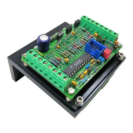
Page 4: Description
General information Description The BLD 3502-SE2P is a 2-Quadrant PWM (Pulse-Width Modulation) Servo Amplifier suitable for speed control of our three-phase brushless DC-Servomotors, type 1628, 2036 and 2444. The phase commutation sequence of the brushless DC-Servomotor is automatically made by the Servo Amplifier. -
Page 5: Maximum Ratings
Technical data Maximum ratings 3502-SE2P Power supply V DC Logic and analog inputs -0,3 to +10 V DC Continuous output current @ T = 22°C Specific characteristics Power Stage: 12 ÷ 35 – Power supply V DC – Total output voltage drop (I =2A) V DC motor... -
Page 6: General Characteristics
General characteristics General characteristics 6.1 Analog Speed command The speed command is given by an external voltage from 0 to +5 V (optional 0 to +10 V) or by a potentiometer connected directly to the Servo Amplifier (see fig. 5). The total potentiometer resistance must be between 10 kΩ... -
Page 7: Analog Speed Command
General characteristics 6.7 Basic block diagram for speed control with Hall sensor feedback Speed amplifier Phase Brushless Analog speed Phase DC-Servomotor Driver command – Phase 1628 ... B 2036 ... B 2444 ... B Hall sensor Enable Hall sensor Brake Hall sensor Direction (CW/CCW) -
Page 8: Brushless Dc-Servomotor With Hall Sensors Feedback (Standard
Start-up procedure 7. Start-up procedure Brushless DC-Servomotor with Hall sensor feedback (standard) Procedure References - Connect the Servo Amplifier 7.2 Connection diagram - Connect Brake Pin 7 with GND Logic Pin 3 7.5 Speed range selection - Select R13 resistance - Power the Servo Amplifier - Verify the operation Connection diagram... -
Page 9: Brushless Dc-Servomotor With Encoder Feedback (Optional
Start-up procedure Servoamplificatore BLD 3502-SH2P 7.3 Brushless DC-Servomotor with encoder feedback (optional) References Procedure 7.4 Connection diagram - Connect the Servo Amplifier - Connect Brake Pin 7 with GND Logic Pin 3 - Connect the encoder 7.6 Speed range selection - remove the two jumpers on X4 - Select R13 resistance and C7 capacitor - Power the Servo Amplifier... - Page 10 Start-up procedure 7.5 Brushless DC-Servomotor with encoder IE2 – 512 References Procedure 7.4 Connection diagram - Connect the Servo Amplifier - Connect Brake Pin 7 with GND Logic Pin 3 - Connect the encoder 7.6 Speed range selection - remove the two jumpers on X4 - Select R13 resistance and C7 capacitor - Power the Servo Amplifier - Verify the operation...
-
Page 11: Speed Range Selection With Hall Sensors Feedback
Start-up procedure Speed range selection with Hall sensor feedback Select R13 resistance adapted to the specific application also taking the motor characteristics into consideration. [rpm] R13 [kΩ] Gain [rpm/V] 60 000 12 270 50 000 10 250 40 000 7 720 30 000 6 400 26 500... -
Page 12: Speed Range Selection With Encoder Feedback
Start-up procedure Speed range selection with encoder feedback Select R13 resistance and C7 capacitor adapted to the specific application taking both the motor and encoder characteristics into consideration. [rpm] R13 [kΩ] C7 [nF] Gain [rpm/V] 7 700 000 / CPR 0,18 1 490 000 / CPR 3 800 000 / CPR... - Page 13 Notice of use 8. Notice of use Power supply Any unstabilized DC power supply voltage within the servo amplifier range (12 V ≤ Vm ≤ 35 V) may be used, although it is advisable to keep this voltage as low as possible in order to minimize the EMI noise. Thus the optimum power supply is given by the following relation: [V] ≈...
- Page 14 Notice of use Action From Self Length 1. No special care 0.3 m 2. Twisted wires (see figure 7) slightly slightly slightly 1.0 m 3. Shielded Hall sensor wires 5.0 m (see figure 8) 4. Shielded Hall sensor and 5.0 m phases wires (see figure 9) perturbations To environment reduced From:...
- Page 15 Twisted wires Yellow Phase C Orange Phase B Brown Phase A Black GND Logic Brushless + VCC DC-Servomotor Grey Hall sensor C Blue Hall sensor B Green Hall sensor A Connector X1 Figure 8 Shielded Hall sensor wires Phase C Yellow Phase B Orange...
- Page 16 The FAULHABER Group: DR. FRITZ FAULHABER GMBH & CO. KG Daimlerstraße 23 71101 Schönaich · Germany Tel.: +49 (0)7031/638-0 Fax: +49 (0)7031/638-100 Email: info@faulhaber.de www.faulhaber.de MINIMOTOR SA 6980 Croglio · Switzerland Tel.: +41 (0)91 611 31 00 Fax: +41 (0)91 611 31 10 Email: info@minimotor.ch...
Need help?
Do you have a question about the Series BLD 3502 and is the answer not in the manual?
Questions and answers