
Summary of Contents for VP VPFlowScope M
- Page 1 VPINSTRUMENTS.COM VPFlowScope M User manual © 2016 Van Putten Instruments BV MAN-VP-MPRO-UK-1602 Date:20-10-2016...
- Page 2 VPFlowScope M © 2016 Van Putten Instruments BV All rights reserved. No parts of this document may be reproduced in any form or by any means - graphic, electronic, or mechanical, including photocopying, recording, taping, or information storage and retrieval systems - without the written permission of the publisher.
-
Page 3: Table Of Contents
Contents Table of Contents 1 Warning - Read this first 2 Introduction 3 Product overview 1 VPFlowScope M transmitter ........................... 7 2 VPSensorCartridge ........................... 8 3 Safety system ........................... 9 4 Configuration ........................... 9 4 Quick start 5 Measurement 1 Flow ........................... - Page 4 1 Transmitter ........................... 45 2 VPSensorCartridge ........................... 45 3 Accessories ........................... 45 16 Appendix A - Underwriters Laboratories (UL) 17 Appendix B - Federal Communications Commission (FCC) Statement © 2016 Van Putten Instruments BV | MAN-VP-MPRO-UK | Revision:1602 | Date:20-10-2016...
-
Page 5: Warning - Read This First
Feedback leads to product improvement. Please share your experience with us, as we are continuously improving our products in our commitment to quality, reliability and ease of use. Let us know via sales@vpinstruments.com! © 2016 Van Putten Instruments BV | MAN-VP-MPRO-UK | Revision:1602 | Date:20-10-2016... -
Page 6: Introduction
Introduction Congratulations! You purchased the easiest to use and most complete compressed air measurement tool in the world. With the VPFlowScope M, you can monitor flow, pressure, temperature, and total air consumption, simultaneously. The optional data logger enables you to record all 4 parameters. -
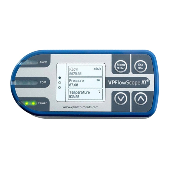
Page 7: Product Overview
Product overview VPFlowScope M transmitter Meet the transmitter, the 'brains' of the VPFlowScope M. The transmitter is one part of the VPFlowScope M which needs to be combined with a VPSensorCartridge and a safety system. The transmitter features various outputs. Modbus, 4..20 mA, pulse, USB, Ethernet, alarm are all standard. -
Page 8: Vpsensorcartridge
The VPSensorCartridge has a flow direction indicator in the shape of an arrow that points in the positive direction. The indicator can be used for proper alignment. Available VPSensorCartridge models Order Code Flow Temperature Pressure Bi-directional VPM.R150.P350.PN10 VPM.R150.P351.PN10 Available models on day of printing © 2016 Van Putten Instruments BV | MAN-VP-MPRO-UK | Revision:1602 | Date:20-10-2016... -
Page 9: Safety System
VPSensorCartridge Configuration The VPFlowScope M needs only one step to be ready for basic operation. It needs to know the exact inner pipe diameter for accurate measurement, wrong inner diameter will lead to very significant misreadings. The pipe diameter can be programmed with the keypad on the display module, via the built-in Web interface or with the VPStudio configuration software. -
Page 10: Quick Start
For installation of the VPFlowScope M, an insertion point needs to be created. A socket with internal 1/2 inch thread is required A ball valve with a minimum size of 0,5 inch female BSP or NPT process connection should be in... -
Page 11: Measurement
1 second: Actual totalizer data will be available on the display and via the Modbus interface. The totalizer value is written to it's internal memory with an interval of 15 minutes. A © 2016 Van Putten Instruments BV | MAN-VP-MPRO-UK | Revision:1602 | Date:20-10-2016... - Page 12 See chapter 9 for Modbus registers. The totalizers can only be reset to zero, and will be reset all together. It's not possible to set them to any different value. © 2016 Van Putten Instruments BV | MAN-VP-MPRO-UK | Revision:1602 | Date:20-10-2016...
-
Page 13: Mechanical Installation
VPInstruments hot tap saddle can be used. Use a 1/2" full bore ball valve to insert and retract the VPFlowScope M when you want. Warning: Make sure that the hole is at least 16 mm | 0.63 inch, and completely clear for insertion. - Page 14 VPFlowScope M Installation procedure Insertion depth Generally the insertion depth of the VPFlowScope M is 0.5 times the inner pipe diameter, where the bottom of the sensor tip must be in the middle of the pipe (see picture). Position Install the VPFlowScope M upwards in an angle between 1 and 2 o'clock (see picture).
-
Page 15: Piping Table
VPFlowScope M. The upstream length is the length between the last non-straight object and the VPFlowScope M. If the upstream length is straight, and the distortion is downstream of the VPFlowScope M, you can use the column "downstream length" as a guideline. In very complex situations, with multiple up- and downstream objects, you should consider another location. -
Page 16: Safety System
1. Mount the nut, and close tight. Then long threaded end side mount the compression fitting's teflon 2. Place the safety plate over the compression fitting rings and nut long threaded end © 2016 Van Putten Instruments BV | MAN-VP-MPRO-UK | Revision:1602 | Date:20-10-2016... -
Page 17: Assembling And Installing The Instrument
2. Align the probe with the display (default safety line is secured position, arrow should point to the left as on the picture). Tighten the locking ring completely © 2016 Van Putten Instruments BV | MAN-VP-MPRO-UK | Revision:1602 | Date:20-10-2016... - Page 18 Step 7 1. Unscrew the safety lock and pull the safety line tight 2. Tighten the safety lock 3. Align the flow direction. Alignment by the eye is sufficient © 2016 Van Putten Instruments BV | MAN-VP-MPRO-UK | Revision:1602 | Date:20-10-2016...
-
Page 19: Replacing The Vpsensorcartridge
Step 4 1. Unscrew the locking ring and slide it 1. Replace the VPSensorCartridge downwards 2. Put the transmitter aside 3. Remove the safety cable from the VPSensorCartridge © 2016 Van Putten Instruments BV | MAN-VP-MPRO-UK | Revision:1602 | Date:20-10-2016... - Page 20 2. Open the ball valve slowly and push the VPFlowScope M probe gently downwards. 3. The probe tip should be in the centre of the pipe 4. Tighten the compression fitting © 2016 Van Putten Instruments BV | MAN-VP-MPRO-UK | Revision:1602 | Date:20-10-2016...
- Page 21 Step 9 1. Loosen the safety lock and pull the safety line tight 2. Tighten the safety lock 3. Align the flow direction. Alignment by the eye is sufficient © 2016 Van Putten Instruments BV | MAN-VP-MPRO-UK | Revision:1602 | Date:20-10-2016...
-
Page 22: Connectivity & Communication
Flow /min Flow /sec Flow SCFM Pressure bar (g) Pressure psi (g) Temperature °C Temperature °F Temperature All flow & velocity units are under normalized conditions (DIN 1343) © 2016 Van Putten Instruments BV | MAN-VP-MPRO-UK | Revision:1602 | Date:20-10-2016... -
Page 23: Pulse Output
In this way we ensure that the pulse output will always be synchronized with the internal totalizer of the transmitter. Pulse output © 2016 Van Putten Instruments BV | MAN-VP-MPRO-UK | Revision:1602 | Date:20-10-2016... -
Page 24: Rs485
VPStudio, via the web server or by using the key pad. Default settings IP address 192.168.1.100 Net mask 255.255.255.0 Gateway 192.168.1.254 Web server port* Modbus port* *Values are fixed and can not be changed © 2016 Van Putten Instruments BV | MAN-VP-MPRO-UK | Revision:1602 | Date:20-10-2016... -
Page 25: Internal Web Server
Display The display enables you to read measurement data in real time. In combination with the keypad, it can also be used to change the most common parameters. © 2016 Van Putten Instruments BV | MAN-VP-MPRO-UK | Revision:1602 | Date:20-10-2016... -
Page 26: Display
A custom unit consist of a base unit, a multiplying factor and a label. For example: Base unit: m Label: SCFM Factor: 0.58 If the actual flow is 10 m /hr, the display will show 5.8 SCFM © 2016 Van Putten Instruments BV | MAN-VP-MPRO-UK | Revision:1602 | Date:20-10-2016... -
Page 27: Keypad
2. New session 3. Delete session 4. Delete all sessions 3. Alarm 1. Mode 2. Unit 3. Boundaries 4. Periods 4. Info / about 5. Factory reset 6. Restart © 2016 Van Putten Instruments BV | MAN-VP-MPRO-UK | Revision:1602 | Date:20-10-2016... - Page 28 HH:MM:SS, again confirm with enter. The new date will become active immediately. Date/time settings are kept actual by the real time clock. This clock is powered by a backup battery © 2016 Van Putten Instruments BV | MAN-VP-MPRO-UK | Revision:1602 | Date:20-10-2016...
- Page 29 Set the hold and reset period for alarm events. 3.5 Reset Reset the alarm counter. The alarm counter can only be reset to zero. See chapter alarm for more information. © 2016 Van Putten Instruments BV | MAN-VP-MPRO-UK | Revision:1602 | Date:20-10-2016...
-
Page 30: Data Logger
It's not possible to append to an existing session. When a power failure occurs during recording, the session will be stopped. When power is restored, a new session will start automatically. © 2016 Van Putten Instruments BV | MAN-VP-MPRO-UK | Revision:1602 | Date:20-10-2016... -
Page 31: Alarm
15 minutes. A power failure may result in a maximum of 15 minutes of alarm counter loss. © 2016 Van Putten Instruments BV | MAN-VP-MPRO-UK | Revision:1602 | Date:20-10-2016... -
Page 32: Modbus
Floating point Read Flow m 006E - 006F 110 - 111 Floating point Read Flow m /min 0070 - 0071 112 - 113 Floating point Read Flow m /sec © 2016 Van Putten Instruments BV | MAN-VP-MPRO-UK | Revision:1602 | Date:20-10-2016... - Page 33 Totalizer positive MSCF Floating point Read 0104 - 0105 260 - 261 Totalizer negative MSCF Floating point Read 0113 - 0114 275 - 276 32-bit integer Read Totalizer m © 2016 Van Putten Instruments BV | MAN-VP-MPRO-UK | Revision:1602 | Date:20-10-2016...
- Page 34 VPSensorCartridge connection status Modbus return value Description No VPSensorCartridge connected VPSensorCartridge is connected VPSensorCartridge is connected but not powered VPSensorCartridge error, see error code and contact local distributor © 2016 Van Putten Instruments BV | MAN-VP-MPRO-UK | Revision:1602 | Date:20-10-2016...
- Page 35 /min /sec SCFM °C °F Other /sec Alarm mode Alarm off Alarm on low boundary Alarm on high boundary Alarm on both boundaries Other Alarm on both boundaries © 2016 Van Putten Instruments BV | MAN-VP-MPRO-UK | Revision:1602 | Date:20-10-2016...
-
Page 36: Electrical Connections
Ohm's law can be used to calculate the maximum distance. There are 2 parameters that needs to be taken into account. 1. The voltage available is equal to the input voltage 2. The resistance depends on cable quality and length © 2016 Van Putten Instruments BV | MAN-VP-MPRO-UK | Revision:1602 | Date:20-10-2016... -
Page 37: Pulse
The counter can be placed between the pulse output and the power supply - (neg). Cabling The electrical specifications are identical to the 4..20mA output. Therefore the suggested cabling is identical. Electrical scheme © 2016 Van Putten Instruments BV | MAN-VP-MPRO-UK | Revision:1602 | Date:20-10-2016... -
Page 38: Alarm
Shielded twisted pair should be used. Connection of a third wire between the master and slave should be done to limit the common mode voltage that can be impressed on the slaves inputs. The © 2016 Van Putten Instruments BV | MAN-VP-MPRO-UK | Revision:1602 | Date:20-10-2016... - Page 39 1 KΩ Bus power The VPFlowScope M can be powered via the same trunk line. 2 separate wires are used for power + and power -. Take in account that long wires with multiple slaves will cause voltage drops. The minimum supply voltage is 12VDC measured at the last VPFlowScope M in the daisy chain.
-
Page 40: Ethernet
We offer 2 types of cables for connecting your transmitter to the Ethernet. Order code Connectors Description VPA.5004.0005 M12 to RJ45 Connection to routers or switches 5 meter | 16.4ft VPA.5004.0105 M12 to M12 Extension cord 5 meter | 16.4ft © 2016 Van Putten Instruments BV | MAN-VP-MPRO-UK | Revision:1602 | Date:20-10-2016... -
Page 41: Vpstudio Software
Electrical connections VPStudio software The VPFlowScope M can be read out and configured with the VPStudio software. This software can be downloaded from www.vpinstruments.com. VPStudio is available for Windows and has been tested on version: Windows 7, 8 and 10. -
Page 42: Exchanging Vpsensorcartridges
All settings are stored in the transmitter and are automatically transferred to the newly installed VPSensorCartridge. Your benefits: Near zero downtime Less logistics/customs cost and involvement Exchanging instructions can be found in chapter Replacing the VPSensorCartridge. © 2016 Van Putten Instruments BV | MAN-VP-MPRO-UK | Revision:1602 | Date:20-10-2016... -
Page 43: Specifications Transmitters
These voltage drops have to be taken into account when designing and implementing the electrical installation. The VPFlowScope M continuously monitors available input voltage and will automatically turn into power save mode when the supply voltage drops below 11.8 Volt. For maximum power reliability under all circumstances, we recommend to use 24 VDC. -
Page 44: Specifications Vpsensorcartridges
Anodized Aluminum, Stainless steel 316, Glass, Epoxy Corrosion resistance Highly corrosive or acid environments should be avoided Electrical Connection type VPSensorCartridge proprietary Power consumption See transmitter specifications for combined power consumption © 2016 Van Putten Instruments BV | MAN-VP-MPRO-UK | Revision:1602 | Date:20-10-2016... -
Page 45: Order Information And Accessories
VPA.5004.0001 Compression fitting for VPFlowScope M with integrated safety system VPA.5004.1001 Locking ring for VPFlowScope M VPA.5014.003 Explorer case for VPFlowScope M VPStudio software SFT.5003.500 VPStudio 2.0 © 2016 Van Putten Instruments BV | MAN-VP-MPRO-UK | Revision:1602 | Date:20-10-2016... -
Page 46: Appendix A - Underwriters Laboratories (Ul)
Electrical connection guidelines- UL 508 Listing for USA & Canada (Check label to see if product is UL marked) The VPFlowScope M is intended to be used with a Class 2 power source or Class 2 transformer in accordance with UL1310 or UL1585. As an alternative a LVLC (Low Voltage Limited Current) power source,... -
Page 47: Appendix B - Federal Communications Commission (Fcc) Statement
Appendix B - Federal Communications Commission (FCC) Statement An FCC grant of equipment authorization and an FCC ID are not required, but the equipment complies with FCC technical requirements. © 2016 Van Putten Instruments BV | MAN-VP-MPRO-UK | Revision:1602 | Date:20-10-2016... - Page 48 EASY INSIGHT IN ENERGY FLOWS VPInstruments Buitenwatersloot 335 2614 GS Delft The Netherlands info@vpinstruments.com www.vpinstruments.com MAN-VP-MPRO-UK-1602 Date: 20-10-2016...
Need help?
Do you have a question about the VPFlowScope M and is the answer not in the manual?
Questions and answers