Yamato SM300 Manual

Yamato SM300 Manual

High pressure steam steriliser

Advertisement

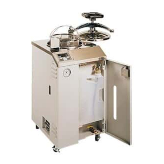
High Pressure Steam Sterilizer
● Thank you for your Yamato Scientific RE series Rotary Evaporator purchase
● For best test data, we recommend you purchase our BM series Water Bath.
Please call Yamato Scientific for more details.
SM200 SM300
SM310 SM510
Second Edition
Read and apprehend the important warnings in
this instruction manual prior to use.
Yamato Scientific America Inc.
Santa Clara, CA
(800) 292-6286

Advertisement

Table of Contents
loading

Summary of Contents for Yamato SM300

  • Page 1 SM200 SM300 SM310 SM510 Second Edition ● Thank you for your Yamato Scientific RE series Rotary Evaporator purchase ● For best test data, we recommend you purchase our BM series Water Bath. Please call Yamato Scientific for more details. Read and apprehend the important warnings in this instruction manual prior to use.
  • Page 2: Table Of Contents

    Table of Contents 1. Specifications ..........................1-2 2. Safety Information.......................... 3-7 Safety Symbols............................ 3 Safety Precautions ........................... 4-6 Hazardous Material ..........................7 3. Identification of Parts........................8-11 External..............................8 Internal............................9-10 Control Panel ............................. 11 4. Installation........................... 12-18 Environmental Requirements ....................... 12-13 Power Requirements .........................
  • Page 3: Specifications

    Specifications SM200/300 Model SM200 SM300 System Automatic high pressure steam sterilizer 105℃∼123℃ 105℃∼128℃ Temperature Sterilization Setting Range 150℃∼180℃ Drying Maximum Operational Pressure 0.18MPa (26.1psi) 0.2MPa (29.0psi) Power Requirement AC115V 13A (50/60Hz) AC115V 17A (50/60Hz) Controller HiTec IV CR Type Microprocessor Control Pt100Ωresistance thermometer sensor...
  • Page 4 Specifications SM310/510 Model SM310 SM510 System Automatic High pressure steam sterilizer 105℃∼128℃ Temperature Sterilization Setting Range 150℃∼180℃ Drying Maximum Operational Pressure 0.2MPa (29.0psi) Power Requirement AC220V 11A (50/60Hz) Controller HiTec IV CR Type Microprocessor Control Pt100Ωresistance thermometer sensor Sensor 1 (Chamber Temp.) Sensor 2 (Water Temp.) Thermocouple (Type T) 1min.
  • Page 5: Safety Information

    Safety Information Safety Symbols Safety Information This instruction manual contains various symbols and safety information. Ignoring safety information can cause such situations as listed below. Please read the following warning and caution signs in this manual prior to use. Warning Indicates the possibility of serious or fatal injury.
  • Page 6: Safety Precautions

    If smoke or any strange odor should disburse from this unit, turn the breaker off immediately and pull out the main power cord. Then contact Yamato Scientific. Neglecting this procedure can result in fire or electric shock. Never try repairing the unit yourself.
  • Page 7 Safety Information Safety Precautions Do not plug the exhaust. Any obstruction in the exhaust may cause the tank to build pressure and become hotter the normal. Do not attempt to open the sterilizer lid until the pressure is at “0psi”. If you attempt to open the lid when pressurized high pressure steam could cause serious bodily injury.
  • Page 8: Safety Precautions

    Safety Information Safety Precautions In the event of electrical storm turn off the main circuit breaker. Neglecting this procedure can result in fire, electric shock or other troubles due to thunderbolts. In the event of a power interruption or the main circuit breaker is switched off during operation the sterilizer solenoid exhaust valve will remain closed once power has been restored.
  • Page 9: Hazardous Material

    Safety Information Hazardous Material The following material is not recommended for use on the sterilizer Nitroglycol, Nitroglycerin, Nitrocellulose and other explosive nitric esters. Trinitrobenzene, Trinitrotoluene, Picric acid, and other explosive Explosive Explosive nitro compounds. Substance Peracetic acid, Methyl ethyl ketone peroxide, Benzoyl peroxide and other organic peroxides.
  • Page 10: Identification Of Parts

    Identification of Parts External Handle Panel Guard Control Panel Exhaust (U-shaped Pipe) Pressure Gauge Steam Saucer Door Latch Bottle Water Window Viewer Louver Louver Pressure Relief Switch Circuit Breaker Louver Terminal (Optional) Power Cord...
  • Page 11: Internal

    Identification of Parts Internal Thermal Insulator Chamber Safety Valve Filter Sensor 1 (For Chamber Temperature) Heater 1 (For Sterilization) Service Plug Sensor 2 (For Water Temperature) Solenoid Exhaust Valve Solenoid Drain Valve Micro Switch Bottom Plate Heater 2 (For Drying)
  • Page 12 Identification of Parts Internal Micro Switch Plug Silencer Drain Valve Exhaust Hose Solenoid Exhaust Port Sensor 2 (For Water Temperature) Flange Clamp Filter Heater 1 (For Sterilization) Sensor 1 (For Chamber Temperature)
  • Page 13: Control Panel

    Identification of Parts Control Panel ⑤ ⑦ ⑥ ⑬ ⑭ ⑧ ⑪ ⑨ ⑫ ⑩ ③ ④ ① ② ① ENTER key Start and stop operation, fix the set point/function changed. ② △▽(up down) key Change set point/function. ③ MENU key Choose “STERILIZE”...
  • Page 14: Installation

    Installation Environmental Requirements Area of installation Never install sterilizer near any flammable, explosive, or corrosive gas components. Fire, explosion, or other troubles may occur when turning the breaker on and off. Area of installation The sterilizer should not be installed in the following environments.
  • Page 15 Installation Environmental Requirements Provide ample space surrounding the sterilizer Provide ample space surrounding the unit as indicated below. ・ Space for lid to open...13 inches or more ・ Space to open door..10.2 inches or more ・ Space for ventilation...5.9 inches or more Do not install under a low ceiling An abundant amount of steam will spout out of the lid just after operation.
  • Page 16: Power Requirements

    To prevent shock from electric current leak, be sure to connect the ground lead. Contact Yamato Scientific or an electrician if a power source with a ground terminal is needed. Never connect ground to with gas pipe, water pipe, telephone line, or lighting conductor.
  • Page 17: Initial Set Up

    Installation Initial Set Up Filter Installation Be sure to install the filter prior to operation. Install the bottom plate The bottom plate balances the material in the chamber and protects heater 1 and sensor 2. Be sure to install the plate. Bottom Plate (at a level) Close the drain valve...
  • Page 18 Installation Initial Set Up Install the bottle The sterilizer drains water forcibly during the “STERILIZE & DRY” process. Hot and high pressure water will spout out to the bottle. To prevent the user from operating the sterilizer without the drain bottle a micro switch will not allow the sterilizer to operate without the bottle. ①...
  • Page 19 See table on right for water volume Requirement information. Using over the maximum level 1900∼2000ml SM200 of water will result in hot water spouting 2800∼3000ml SM300 from the bottle. 2800∼3000ml SM310 2800∼3000ml SM510 Use distilled water for sterilization Use distilled water to prevent collection of mineral deposits and corrosion of chamber components.
  • Page 20: Installation

    Installation Initial Set Up Close the door before operation Be sure to close the front door of the sterilizer before operation. An open door may cause the bottle to fall during operation. Do not open the front door during operation. Close the lid Be sure to close the lid completely by turning CLOSE...
  • Page 21: Operational Precautions

    Operational Precautions Opening lid When opening the lid, be sure that the OPEN pressure gauge reads “0psi". Proceed to open slowly. If the lid is opened at high pressure, hot steam will spout out. Drainage After operation, the water in the chamber is very hot.
  • Page 22 Operational Precautions Certain areas become very hot During and following operation, the areas around the lid become very hot. Be careful not to touch these areas. ◆ Gray areas in the illustration on the right become especially hot. Lid gasket Any damage or dust on the lid gasket/flange of the chamber (gray area in illustration on right) will allow steam to escape.
  • Page 23: Sample Run Examples

    Sample Run Examples How to operate the “STERILIZE” process Sterilize operation using a waste bag. ① Be sure to open the mouth of the bag to let steam. ② Keep the bag approximately 2/3” height of the total depth of the chamber (Example: SM200 is 17.5”...
  • Page 24: Program "Mode

    Program “MODE” “MODE” key Information How to use the “MODE” key →Main display starts blinking Turn the circuit breaker on. Push the “MODE” key. The sterilizer automatically starts in (Sterilization Temp.) stand-by mode, and the display show current set point. Setting other parameters ・...
  • Page 25: Display Symbols

    Program “MODE” Display Symbols List of Symbols in the display Symbol Word Meaning BOTTLE Bottle : Bottle isn’t set. DRY TEMPERATURE Function of setting drying temperature. DRY TIME Function of setting drying time. End : To indicate the end of operation. ERROR Error : To indicate the occurrence of trouble.
  • Page 26: Flowchart

    Program “MODE” Flowchart...
  • Page 27: Setting Sterilization Temperature And Time

    Program “MODE” Setting Sterilization Temperature and Time Setting sterilization temp/time ◆ Used to set the sterilization temp/time. ◆ Simply push the ”MODE” key to cancel the set up at any point. ◆ The sterilizer automatically sets in stand-by mode if it is untouched for more than a minute during set up.
  • Page 28: Setting Dry Temperature And Time

    Program “MODE” Setting Dry Temperature and Time Dry Mode Temperature and Time Input the dry temperature you desire by ▽△key. ▽key…To lower temperature to 150℃. △key…To raise temperature up to 180℃. Temp. Push the “ENTER” key. The changed dry temperature is fixed, and the panel blinks the next function, dry time set-up.
  • Page 29: Special Program Features

    Program “MODE” Special Program Features Buzzer Signal on - buzzer at the end of a cycle Signal off - no sound alert at the end of a cycle prior to or during operation. ◆ You may select the “Signal on/off”. Selection of “signal on/off”...
  • Page 30: Run "Menu

    Run “MENU” Selection of Operation Selecting operation The following procedure allows the user to select the desired operation. ・ Turn on main circuit breaker. ・ Push “MENU” key to select sterilize. Push “MENU” key again to select sterilize & dry. ●Menu change can only be made during stand-by mode.
  • Page 31: Sterilize" Procedure

    Run “MENU” “STERILIZE” Procedure “STERILIZE” procedure Check the following: ① Is the drain valve closed? Pg.10 ② Is the drain filter in place? Pg.15 ③ Is the bottom plate set? Pg.15 ④ Is the bottle set? Pg.16 ⑤ Is water in chamber? Pg.17 ⑥...
  • Page 32 Run “MENU” “STERILIZE” Procedure When the chamber temperature reaches the set temperature, sterilization process begins and the time counter starts. At this time, the sub display will show the sterilization time remaining. →The main display shows chamber temperature. →The sub display shows the remaining sterilization time. →Sterilize lamp is lit.
  • Page 33: Sterilize & Dry" Procedure

    Run “MENU” “STERILIZE & DRY” Procedure “STERILIZE & DRY” procedure Check the following. ① Is the drain valve closed? Pg.10 ② Is the drain filter in place? Pg.15 ③ Is the bottom plate set? Pg.15 ④ Is the bottle set? Pg.16 ⑤...
  • Page 34 Run “MENU” “STERILIZE & DRY” Procedure After chamber temperature reaches the set temperature, sterilization process starts. The sub display shows the sterilization time. →The main display shows chamber temperature. →The sub display shows the remaining sterilization time. →Sterilize lamp blinks. →Sterilize &...
  • Page 35 Run “MENU” “STERILIZE & DRY” Procedure When the drying time is completed, the heater is turned off and natural cooling starts. →The main display shows chamber temperature. →The sub display blinks →End lamp is lit. →Sterilize & Dry menu lamp is lit. ◇...
  • Page 36: Special Control Functions

    Special Control Functions View Parameter during Operation To check set temperature and time during the operation, push the “MODE” key. Set points can only be viewed, not changed. ◇ Push the “MODE” key. →The main display blinks (set Temp). →The sub display shows the set temperature. →Set lamp is lit.
  • Page 37: Interrupt Program During Operation

    Special Control Functions Interrupt Program during Operation ◇Push the “ENTER” key. Operation is interrupted. Steam will exhaust when pressurized. →The main display shows current chamber temp. →The sub display blinks ◇Push the “ENTER” key twice to resume operation. →The main display blinks the set temperature. →The sub display blinks the set time.
  • Page 38: Troubleshooting Guide

    Safety Self-diagnostic Circuitry The Yamato sterilizer was designed with self-diagnostic circuitry capable of monitoring operation of the sterilizer. If a malfunction occurs, the display panel blinks the error code and an alarm is sounded. The microprocessor disables power to the heater element. If this occurs, check the error code and immediately shut off the main breaker.
  • Page 39: Problem Solving Chart

    The operation does not start from ・ Is bottle installed? stand-by. ・ Is the silencer out of place? Noise during air purge is loud. ◆ If you require further technical assistance, please call Yamato Scientific at (800) 292-6286 Ext. 235...
  • Page 40: Wiring Diagram

    Wiring Diagram SM200 SM300 ◆ Inside of dashed line is option...
  • Page 41: Wiring Diagram

    Wiring Diagram SM310/510 ◆ Inside of dashed line is option Symbol Name of Parts Symbol Name of Parts Transformer PIO2 Pio2 Board Relay POWER2 Power2 Board Current Transformer Pressure Relief Switch Solid State Relay Micro Switch Circuit Breaker Sensor 2 (Thermocouple) Terminal Sensor 1 (Pt100 resistance thermometer) Solenoid Exhaust Valve...
  • Page 42: Piping Chart

    Piping Chart Solenoid Exhaust Valve (MV1) Solenoid Drain Valve (MV2) Chamber Pressure Gauge Safety Heater 2 Valve Sensor 1 Heater 2 Sensor 2 Bottle Drain Valve Heater 1 Silencer...
  • Page 43: Maintenance

    The door gasket, located under the lid of the sterilizer can be wiped clean with a clean damp cloth. The gasket should be examined for cracks or damage that can result in a poor pressure seal. If replacement is needed, contact Yamato Scientific. Cleaning the Pipe Heater The pipe heater should be cleaned twice a month.
  • Page 44: Monthly Maintenance

    Maintenance Monthly Maintenance Cleaning the silencer The unit is set up with a silencer at the end of the Silencer exhaust hose to reduce noise occurring from air purge. Remove the silencer and clean with water once a month. ◆ A ball is set in the silencer to prevent back flow of water.
  • Page 45: After Sale Service And Warranty

    We can not accept any products or parts returned to us for repair or credit that is contaminated with or has been exposed to potentially infectious agents or radioactive materials. If you need repair, please call Yamato Scientific at (800) 292-6286 Ext. 221 for a Return Authorization Number. No product will be accepted without this number.
  • Page 46: Replacement Parts List

    SM51A-30490 W467 Current Transformer 2-17-001-0002 URP CTL-6-5-400 Pressure Relief Switch 2-01-001-0014 A2A-4W Circuit Breaker (SM200/310/510) 2-06-001-0003 BS2021 Circuit Breaker (SM300) 2-06-001-0004 BS2022 Heater 1 (SM200) 2-24-000-0057 AC115V 1.3kw Heater 1 (SM300) 2-24-000-0058 AC115V 1.7kw Heater 1 (SM310/510) 2-24-000-0059 AC220V 2.0kw...
  • Page 47 Responsibility Please follow the instructions in this document when using this unit. Yamato Scientific has no responsibility for the accidents or breakdown of device if it is used with a failure to comply. Never conduct what this document forbids. Unexpected accidents or breakdown may result in.

This manual is also suitable for:

Sm200Sm310Sm510

Table of Contents