
Subscribe to Our Youtube Channel
Summary of Contents for A123 Systems APR18650M1-A
- Page 1 USER DOCUMENTATION Date: March 6, 2014 Document #: 493005-002 Rev 02 Battery Pack Design, Validation, and Assembly Guide using A123 Systems Nanophosphate Cells ® Including: APR18650M1-A ANR26650M1-B AHR32113M1Ultra-B AMP20M1HD-A...
- Page 2 Copyright © 2014 A123 Systems, LLC. All rights reserved. DOCUMENT NOTICE AND DISCLAIMER: This document is the property of A123 Systems, LLC. ("A123"). The information in this document is subject to change without notice. A123 is under no obligation to update the information in this document.
-
Page 3: Table Of Contents
Contents Preface ................................... 1 About this Document ..............................1 Purpose of this Document ............................ 1 How to Use this Guide ............................2 Conventions Used in this Guide ..........................2 Related Documents and Resources ........................3 Chapter 1 ..................................4 Possible Dangers Involved With Handling Cells and Battery Packs ................4 Thermal Events .............................. - Page 4 Incoming Cell Inspection ............................. 57 Material Handling and Storage ........................... 57 Cell Welding ................................ 58 Appendix A................................... 61 Cell Specifications ..............................61 AMP20M1HD-A ..............................62 ANR26650M1-B ..............................72 APR18650M1-A ..............................79 AHR32113M1Ultra-B ............................83 Appendix B ................................... 90 Acronyms and Terminology ............................ 90...
- Page 5 Figure 31 – Notes for AMP20M1HD-A cell dimensions drawing ................71 Figure 32 – ANR26650M1-B cell diagram and dimensions ..................78 Figure 33 – APR18650M1-A cell diagram and dimensions ..................82 Figure 34 – AHR32113M1Ultra-B cell diagram and dimensions ................. 89...
- Page 6 Table 26 – APR18650M1-A Max continuous charge currents wrt temperature and SOC .......... 81 Table 27 – APR18650M1-A Max 10s pulse charge currents wrt temperature and SOC ..........81 Table 28 – APR18650M1-A Max continuous discharge currents wrt temperature and SOC ........81 Table 29 –...
-
Page 7: Preface
Preface About this Document Purpose of this Document This guide provides information that may be useful for designing, validating, and assembling battery packs with ® A123 Nanophosphate cells. Creating a well designed battery pack requires many considerations. The scope of this guide is to outline the unique aspects of designing battery packs with A123 Nanophosphate cells. -
Page 8: How To Use This Guide
A danger contains information essential to avoid a hazard that will cause severe personal injury, death, or substantial property damage if the warnings are ignored. Table 1 – A123 Systems cell model numbers Abbreviated Cell Model Numbers A123 Systems Cell Model Numbers... -
Page 9: Related Documents And Resources
Related Documents and Resources • A123 Product Documentation: A123 Energy web site: http://a123energy.com/resources-overview.htm A123 Systems web site: http://www.a123systems.com/resources-overview.htm • http://www.iata.org/whatwedo/cargo/dgr/Pages/lithium-batteries.aspx • http://www.ups.com/media/news/en/intl_lithium_battery_regulations.pdf • http://www.welding-consultant.com • http://www.ccl.fraunhofer.org/ • Sandia Report SAND20053123 “FreedomCar Electric Energy Storage System Abuse Test Manual for Electric and Hybrid Electric Vehicle Applications”... -
Page 10: Chapter 1
Chapter 1 Possible Dangers Involved With Handling Cells and Battery Packs A123’s cells are highly stable and abuse-tolerant; however, handling a battery pack remains potentially dangerous to personnel and property; therefore, anyone attempting to design or handle battery packs must first completely understand all aspects of proper battery pack design and construction. -
Page 11: Thermal Events
Thermal Events A thermal event is one where excessive heat in or around the cell destroys it immediately. Proper battery pack design is essential to allow the thermal safety features of A123’s cells to function as designed. A123 cell design includes a safety feature that allows over-overheated cells to relieve dangerous pressure buildup by venting and dispersing the gases into the environment. -
Page 12: Chapter 2
Chapter 2 Transportation, Storage and Disposal This chapter provides information about transportation regulations, storage specifications, and disposal considerations applicable to A123’s cells and battery packs designed with them. This chapter includes the following sections: • Transporting Batteries • Storing Batteries •... -
Page 13: Transporting Batteries
Transporting Batteries Certain batteries are considered “Dangerous Goods” because of their inherent stored energy and flammability. Lithium ion batteries of a certain size are considered “Class 9” Dangerous Goods and must be transported in accordance with international regulations. Transporting Dangerous Goods is regulated internationally by the International Civil Aviation Organization (ICAO) Technical Instructions and corresponding International Air Transport Association (IATA) Dangerous Goods Regulations and the International Maritime Dangerous Goods (IMDG) Code. -
Page 14: Table 2 - Steps Required To Transport A Lithium Ion Battery
Shipping Process Overview Table 2 provides an overview of the steps typically required to ship a product that contains lithium ion cells both internationally and in the U.S. Table 2 – Steps required to transport a lithium ion battery Step Process Step Comments Number... - Page 15 UN Test Types The UN Manual of Tests and Criteria Section 38.3 consists of the following tests: • Test T.1: Altitude Simulation • Test T.2: Thermal Test • Test T.3: Vibration • Test T.4: Shock • Test T.5: External Short Circuit Test •...
-
Page 16: Table 3 - Nominal Energy And Elc Of A123 Cells
Table 3 shows the nominal Wh ratings and ELC for each of the commercially available A123 cells. Table 3 – Nominal energy and ELC of A123 cells Nominal Capacity Nominal Energy Cell Nominal Voltage Ah Rating APR18650M1-A 3.63 0.33 ANR26650M1-B 8.25 0.75 AHR32113M1Ultra-B 14.9... -
Page 17: Table 4 - Us Transportation Classification Of Cells
US Regulation Requirements Overview For any transport of cells or batteries inside the US borders, by road or rail, Table 4 and Table 5 summarize how cells and batteries are classified with respect to Class 9 Dangerous Goods. For such shipments, cells and batteries are classified by their equivalent lithium content (ELC) as either Class 9 or Excepted. -
Page 18: Table 6 - International Transportation Classification Of Cells
International Regulation Requirements Overview For any transport of cells or batteries outside of the US borders, or transport by ocean OR air anywhere in the world including the US, Table 6 and Table 7 summarize how cells and batteries are classified with respect to Class 9 Dangerous Goods. -
Page 19: Table 8 - International Air Transport Association (Iata) Packaging And Quantity Restrictions (Pi-965)
Using the IATA Rules to Test, Package, and Label The International Air Transport Association (IATA) regulations provide requirements for testing, packaging, and labeling of lithium batteries. These regulations are found in Packing Instructions PI-965 – PI-970. IATA Packing Instructions PI-965, PI-966, and PI-967 apply specifically to air shipment of lithium ion batteries. They provide specific requirements for the materials used and the “survivability”... - Page 20 PI-965 – Lithium Ion Cells and Batteries Section II Section 1B Section 1B Cells and/or Cell Batt. (Cell ≤ 20 (Batt. ≤ 100 batteries ≤ 2.7 Requirement Section 1A* (2.7 Wh < Cell (2.7 Wh < Batt. Wh) and Wh) and Wh and (Class 9) ≤...
-
Page 21: Table 9 - International Air Transport Association (Iata) Packaging And Quantity Restrictions (Pi-966 & Pi-967)
Table 9 – International Air Transport Association (IATA) packaging and quantity restrictions (PI-966 & PI-967) PI-966 – Lithium Ion Cells and Batteries PI-967 – Lithium Ion Cells and Batteries Packed with Equipment Contained in Equipment Requirement Cell Batt. Cell Batt. Class 9 Class 9 ≤... -
Page 22: Storing Batteries
PI-966 – Lithium Ion Cells and Batteries PI-967 – Lithium Ion Cells and Batteries Packed with Equipment Contained in Equipment Requirement Cell Batt. Cell Batt. Class 9 Class 9 ≤ 20 Wh ≤ 100 Wh ≤ 20 Wh ≤ 100 Wh repacking if necessary. -
Page 23: Chapter 3
Chapter 3 Nanophosphate Technology and Cell Characteristics ® This chapter includes the following sections: Nanophosphate Technology Power • Safety • Life • • Nanophosphate Technology A123’s low impedance Nanophosphate electrode technology provides significant competitive advantages over alternative battery technologies, including: •... -
Page 24: Power
Power A123 cells are designed to deliver high power in pulse and continuous applications. Figure 1 shows the cell voltage remains relatively flat during the discharges and the delivered Ah capacity does not change significantly, no matter what the rate of discharge. Cell Discharge Data for Various Discharge Rates Figure 1 –... -
Page 25: Figure 2 - Amp20 Cells Discharge Curves At Various Temperatures
Cell resistance changes with cell temperature. The higher the cell’s temperature, the lower its resistance becomes. Figure 2 shows how temperature affects the cell’s terminal voltage during a one hour discharge. 19.5 A Discharge, 45 °C to -30 °C Figure 2 – AMP20 cells discharge curves at various temperatures* * Discharge data for APR18650, ANR26650 and AHR32113 cells is located in Appendix A, starting on page 61. -
Page 26: Safety
If the cell or battery emits smoke or flames, ventilate the area immediately and avoid breathing the fumes. See the A123 Systems Safety Data Sheet (SDS)* for additional precautions. Cells must not be subjected to reverse polarity or short circuited. Individual cell fusing is required in pack designs with cells in parallel to be compliant with international regulations that are harmonized with the UN Recommendations on the Transport of Dangerous Goods. -
Page 27: Life
Life A123 cells offer long cycle and calendar life, with minimal impedance growth over the life of the cells. The cycle life graph in Figure 3 shows how the capacity of the cell decreases with respect to the number full Depth of Discharge (DoD) cycles that it delivers. -
Page 28: Chapter 4
Chapter 4 Battery Pack Design This chapter includes the following sections: Design Overview Configuration of Cells in a Battery Pack • Battery Pack Structural Design • Cell Protection • Battery Pack Control (Monitoring and Management) • Battery Pack Use • •... -
Page 29: Design Overview
Design Overview A battery pack is a system of multiple components and functions and its design involves the application of knowledge and practice in the electrochemical, electrical, mechanical, thermodynamic, and control fields. The following sections summarize the various stages of a battery pack design, covering specific aspects of the A123 cells which may be unique from other cells. -
Page 30: Configuration Of Cells In A Battery Pack
Configuration of Cells in a Battery Pack The battery pack’s terminal voltage and current ratings must match those of the device(s) to which it interfaces. If the pack requires the energy of just one cell, the designer’s options are limited to the ratings of that one cell. However, as more energy is required of the pack, requiring more cells to be interconnected, the Cell Configuration degrees of freedom increase, allowing the designer to choose a combination of cell-to-cell interconnections that... -
Page 31: Figure 5 - Example Of Amp20 Cells Connected In Series
Series Strings Cells combined in series strings will achieve higher operating voltages by connecting the positive terminal of one cell to the negative terminal of the next cell. Connect strings of series AMP20 cells using their current collection tabs in a manner similar to that illustrated in Figure 5. Figure 5 –... -
Page 32: Figure 6 - Example Of Amp20 Cells Connected In Parallel
Parallel Cells Cells connected in parallel can achieve higher operating power by connecting like-polarity terminals of adjacent cells to each other. Connect groups of parallel cells using their current collection tabs in a manner similar to that illustrated in Figure 6. Figure 6 –... -
Page 33: Battery Pack Structural Design
Battery Pack Structural Design A well designed battery pack protects and replicates the individual cell performance of multiple cells in the pack. It provides mechanical protection and integrity, thermal stability, and electrical protection and performance. The electrical Structure interconnections, mechanical supports and thermodynamic systems are all essential Cell Configuration elements of the battery pack’s structural design. -
Page 34: Figure 7 - Effect Of Amp20 Cell Life With Respect To Surface Pressure
Mechanical Cell Support ANR26650 and APR18650 Cell Support Secure the cells in place by supporting their outside cases, not their terminal ends. The vibration induced between the terminal ends and the rest of the case has been shown to be detrimental to the life of the cell, causing internal and external cell damage. -
Page 35: Figure 8 - Amp20 Cell Thickness Variation Wrt Soc For Three Representative Amp20 Cells
AMP20 Cell Thickness Expansion During the regular cycling that a cell experiences from 100% SOC to 0% and back, the cells will expand approximately 1% their initial thickness. Over the course of the cell’s lifetime as it ages during regular service, its thickness will grow to be 3 –... -
Page 36: Figure 9 - Graph Of The Pressure Vs. Deflection Of An Example Compliant Pad For Amp20 Cells
Compliant Pads Between AMP20 Cells To maintain proper cell support and account for expansion during the charge and discharge cycles, A123 uses a compliant pad between cells. The compliant separator is chosen to maintain the pressure range of 4 – 18 psi against the cell’s surface. -
Page 37: Figure 10 - Pressure On Amp20 Cell Face Without Compliant Pad (Left) And With Compliant Pad (Right)
AMP20 Cell Pressure Uniformity Another advantage of a compliant pad between the cells is that pressure is kept relatively constant across the whole surface of the cell. Figure 10 shows simulated pressures at various points across the cell with and without the compliant pad in place. -
Page 38: Figure 12 - Amp20 Cell Corner That Will Vent Under Extreme Internal Pressure
Cell Environmental Protection In addition to supporting the cells, a well-designed chassis will protect cells from exposure to corrosive substances and oxidizing catalysts, such as dust and moisture. The necessary level of protection for cells in a battery pack varies depending on the intended application. For example, a battery pack designed for use in a vehicle must have an enclosure that isolates cells from shock and vibration, protects them from dirt and debris, as well as shielding them from other environmental dangers, such as salt spray. -
Page 39: Figure 14 - Apr18650 Cell Vents
APR18650 Cell Vents The APR18650 cell vents, located on the end cap(s) of the cells (on the POSITIVE side of the cell), should not be blocked by any mechanical means. Blocking the cell vent and then sufficiently abusing the cell so as to build up pressure in the cell prevents the cell from properly venting. -
Page 40: Figure 15 - Diagram Of Optional Amp20 Cell Cooling Concept
Cooling Tube or Heat sink Figure 15 – Diagram of optional AMP20 cell cooling concept Air convection or liquid-cooled heat sinks or tubes can be used to draw heat away from the ends of the cells. The design choice will be made based on project and product budget and performance requirements. The goal is to keep the cell’s temperatures at or below 35 °C to maximize their service life. -
Page 41: Cell Protection
Cell Protection The battery pack must be protected from inadvertent short circuits internal and Protection external to the pack as well as excessive charging and discharging imposed on its Structure terminals. Cell Configuration Short Circuit Protection Because of the very low impedance of the A123 cells, a short circuit can cause excessive internal and external damage if not limited in either duration or current magnitude. -
Page 42: Figure 17 - Example Amp20 Cell Fuse Pattern In Cell Terminals
The cells provided by A123 do not have any fusing built into the cells. In order to implement cell-level fusing, individual cell fusing can be accomplished by constricting the interconnecting metal material near the cell terminal. For the AMP20 cells this is done by stamping out a pattern of holes in the tabs. Some experimentation and modeling is required to find the right pattern to offer the proper protection and coordination with the entire system. -
Page 43: Figure 19 - Example Of Total System Fusing Strategy
The current-time chart in Figure 19 shows how the cell-level fuse might coordinate with other current limiting devices in the system. Figure 19 – Example of total system fusing strategy Module Fuse Rating The module fuse should blow at a lower current than that of the individual cell fuses. This ensures that the module fuse blows before any of the cell fuses in response to a fault on the module terminals. -
Page 44: Figure 20 - Battery Pack With Representative Short Circuit Faults
Battery Pack Figure 20 – Battery pack with representative short circuit faults Pack Fuse Rating and Position The pack fuse needs to interrupt the full fault current of the battery pack at its worst-case maximum terminal voltage. The pack fuse should be rated such that it carries the system load current continuously at all rated temperatures. -
Page 45: Battery Pack Control (Monitoring And Management)
Battery Pack Control (Monitoring and Management) Control When joining cells together, A123 recommends using a Battery Management System Protection (BMS) to accurately monitor cell voltage, current, impedance and other conditions of Structure the cells. The BMS may be implemented as discrete circuitry and/or through a Cell Configuration microcontroller. - Page 46 If the contact points are placed asymmetrically, such as shown below: Vcell Weld-strap material (with intrinsic resistance Rs per unit length) Vcell i (current) Vm1 = Vcell1 – 3 x i x Rs and Vm2 = Vcell2 – i x Rs. The result of Vm1 – Vm2 would contain an undesirable offset in it: Vcell1 –...
- Page 47 The following circuit depicts a condition in which the measured voltages would be affected by balancing currents going through the sense leads: Vcell Weld-strap material (with intrinsic resistance Rs per unit length) Vcell In such a case, if Rb were connected to cell 1, Vm1 would read Vcell1 – ib x 2 x (Rbs + Rs). Having a separate wire for balancing current from the sensing wires eliminates a good portion of the error, as shown in the following diagram: Vcell...
-
Page 48: Table 10 - Example Of Histogram Data Of Temperature Ranges And Durations
Cell Temperature Ideally, the temperature of every series element or cell would be monitored by the BMS; however, it is not as important as voltage, and is often impractical in cost-effective systems. A high-temperature condition is typically the result of monitored voltage and current conditions either being out of bounds or caused by an external thermal source. - Page 49 Cell Balancing Reasons for Cell Balancing A123 recommends cell balancing circuitry when more than one cell is put in series in a battery pack. This is important to achieve maximum life, reliability and safety. Over time and use, the spread between the highest and lowest cells’...
- Page 50 of each cell can be accurately determined from their terminal voltages. However, if the pack is used in a charge- sustaining application, where it is rarely charged to its full SOC, the cell to cell voltage variation is more difficult to ascertain, because in the mid-SOC range, the voltage is very flat with respect to SOC.
-
Page 51: Figure 21 - Amp20 Cell Voltage Vs. Soc At 23 °C
over SOC and even temperature. Figure 21 & Figure 22 show the two different voltages for each SOC point at 23 °C. Average DOD-OCV hysteresis Average voltage (V) 3.40 3.35 3.30 3.25 3.20 3.15 3.10 100% Figure 21 – AMP20 cell voltage vs. SOC at 23 °C Average DOD-OCV hysteresis Average voltage (V) 3.40... -
Page 52: Figure 23 - Amp20 Cell Temperature Effects On Ocv With Respect To (Wrt) Soc
For a single voltage of 3.3V, the OCV can represent either 70% SOC or 30% SOC depending on whether the cells were just discharged or charged. Because some of the sections of the curve are very flat; < 1 mV per % SOC, even a small 1 mV error in the voltage reading can result in an error of several percent. -
Page 53: Figure 24 - Amp20 Cell 60S, 20A Dcr Measurements Wrt Soc At Various Temperatures
on the actual terminal voltage minus the current times the estimated battery impedance. The impedance is a variable with respect to the actual SOC but especially with temperature. Figure 24 shows the effect on DCR (direct current resistance) by temperature and SOC. Notice there is very little effect on DCR by SOC, but a large effect from temperature. -
Page 54: Battery Pack Use
For more information on integrated circuit battery management systems and AFEs that may work in your application, contact Texas Instruments, Seiko Electronics, Linear Technology, Analog Devices, Maxim, National Semiconductor, or O2-Micro. A123 does not endorse or provide warranty for these companies’ products. Control Battery Pack Use Protection... -
Page 55: Figure 25 - Battery Voltage And Current During Recharge
Table 11 – Charge current and voltage calculation examples Example 1 If a cell group has 3 cells in parallel (3p), and the recommended charge current per cell is 20A, then the charge current for this group is 60A: (3 cells, parallel) x 20A = 60A Example 2 If a cell string has 10 cells in series (10s), and the recommended charge voltage per cell is 3.6V, then the end of charge voltage for the string is... -
Page 56: Figure 26 - Amp20 Cell* Capacity Degradation Vs. Time For Various Recharge Rates
Effect of charge rates for 100% DOD cycling at 23 °C for AMP20 cell Figure 26 – AMP20 cell* capacity degradation vs. time for various recharge rates** * Refer to Appendix A for data on other A123 cells. ** Refer to Appendix A for the recommended fast-charge current limits of A123 cells. Recommended Float Charge Method for Strings To hold the voltage of the cell string at the end of charge voltage (after reaching 100% SOC) for prolonged periods of time, lower the end of charge voltage to the recommended float-charge voltage. - Page 57 loss, at varying degrees. However, a skin temperature above 85 °C is likely to cause immediate harm to the cells and should be avoided at all costs. Recommended Discharge Currents for Strings Determine the maximum continuous discharge current for a string of cells by multiplying the number of parallel cells in the string by the maximum continuous discharge current for a single cell.
- Page 58 Pulse Discharge Limits While the cell or battery can discharge at greater than the maximum continuous discharge current in short pulses, do not allow the individual cells to exceed the maximum allowable cell temperature. During pulse discharges, the cell voltages can safely fall below the recommended discharge cut-off voltage. Although it is safe to temporarily discharge the cell or battery below the recommended discharge cut-off voltage, the cell will suffer a faster rate of permanent capacity loss over its service life when subjected to such repeated discharges.
-
Page 59: Chapter 5
Chapter 5 Summary of Battery Pack Validation To ensure safe operating performance of a battery pack using A123 cells, the battery pack must be designed to pass a critical set of design validation tests. This chapter summarizes the recommended minimal testing to be performed on a battery pack, the performance criteria it must pass, and a set of design guidelines to follow while designing the product. -
Page 60: Performance Testing
Performance Testing Battery pack performance testing validates that the battery pack performs basic functionality in the application’s intended environment. These tests include discharge, recharge, cycling, open circuit, thermal, and environmental testing. Applications for each battery pack can vary significantly, so the key to success is to frame the test conditions around the expected application’s conditions. -
Page 61: Abuse Testing
Abuse Testing Abuse testing verifies reactions to harsh and out-of-specification conditions under which the product may be exposed. The results of these tests do not necessarily have to show that the product survives and functions after such tests. However, it is expected that a result of the abuse test show that the product will cause little or no damage to personnel and objects near them. -
Page 62: Compliance Testing
Compliance Testing Compliance or conformance testing verifies whether a product meets a set of defined standards dependent on the product application. The battery pack needs to meet standards in areas such as safety, environmental, and electromagnetic compliance. This guide cannot cover all possible applications and uses for A123’s cells. Therefore, one must test the pack design based on the compliance standards appropriate for its intended application. -
Page 63: Chapter 6
Chapter 6 Battery Pack Assembly This chapter discusses inspecting cells prior to assembling into packs and guidelines for creating weld schedules for A123 cells. This chapter includes the following sections: • Incoming Cell Inspection • Material Handling and Storage • Cell Welding Incoming Cell Inspection Cells are checked for excessive self-discharge at the factory before they are released for sale and shipment. -
Page 64: Cell Welding
Cell Welding 20 Ah Prismatic Cell Interconnects Cell interconnects (tabs) should NOT be soldered to the battery terminals or attached using extreme heat. A123 recommends resistance or laser welding tabs to the terminals of the cell. Because it is impossible to cover every possible weld schedule, A123 recommends meeting with welding consultants to discuss weld schedules optimized to your specific application. -
Page 65: Figure 28 - Two Types Of Bus Bars Ultrasonically Bonded In The Center To Each Other
In order to join a positive terminal to a negative terminal, two dissimilar metals, copper and aluminum need to be connected. A123 recommends that the copper and aluminum straps should be joined together using a welding a process. A123 joins the two types of metals together using an ultrasonic welding method. The copper bus bar is pre-tinned to resist corrosion and to assist in the bonding to the Al bus bars. - Page 66 Welders You may find these welders useful for your needs: • Unitek IPB5000A inverter welding control and an ITB-780A6 transformer, coupled with the 88A/EZ weld head. • Miyachi MDB-4000B welder coupled with the 88A/EZ weld head • Miyachi IS-120B inverter welding control and an IT-1040-3 transformer, coupled with the 88A/EZ weld head (transformer requires water cooling).
-
Page 67: Cell Specifications
Appendix A Cell Specifications This appendix includes specifications, performance examples, and diagrams for A123’s cells: • AMP20M1HD-A • ANR26650M1-B • APR18650M1-A • AHR32113M1Ultra-B... -
Page 68: Amp20M1Hd-A
AMP20M1HD-A General Specifications Refer to Table 15 for specifications of the AMP20M1HD-A cell and a diagram of cell dimensions in Figure 30 on page 70 . Note that actual performance of the cells may vary depending on use conditions and application. Table 15 –... - Page 69 Handling/Transportation Specifications Do not open, dissemble, crush or burn cell. Do not expose cell to temperatures outside the range of -40 °C to 65 °C. Refer to Chapter 2, on page 6, for more information. Storage Specifications Store cells in a dry location. To minimize any adverse affects on battery performance it is recommended that the cells be kept at room temperature (25 °C +/- 5 °C).
- Page 70 AMP20M1HD-A Maximum Current Limit Tables The max current tables in this section summarize the maximum recommended charge and discharge currents per cell for continuous and pulse operations with respect to SOC and cell temperature. Although the cells are capable of the listed currents and the actual limits for each application may be different depending on the battery pack environment, design, the cell’s age and the immediate and long-term operating history of the cells.
-
Page 71: Table 16 - Amp20M1Hd-A Max Continuous Charge Currents Wrt Temperature And Soc
AMP20M1HD-A Table 16 – AMP20M1HD-A Max continuous charge currents wrt temperature and SOC Temp(°C) %SOC 100% Table 17 – AMP20M1HD-A Max 10s pulse charge currents wrt temperature and SOC Temp(°C) %SOC 100% Table 18 – AMP20M1HD-A Max continuous discharge currents wrt temperature and SOC Temp(°C)... - Page 72 AMP20M1HD-A Characterization Charts AMP20M1HD-A Discharge Data at Various Rates Cell Discharge Data for Various Discharge Rates AMP20M1HD-A Discharge Data at Various Temperatures 19.5 A Discharge, 45 °C to -30°C...
- Page 73 AMP20M1HD-A Cycle Life at Various Temperatures Effect of temperature for 1C/-1C, 100% DOD cycling for AMP20 cells AMP20M1HD-A Calendar Life at Various Temperatures Capacity Loss for 100% SOC storage AMP20 cells...
- Page 74 AMP20M1HD-A Open Circuit Voltage vs. State of Charge Average DOD-OCV hysteresis Average voltage (V) 3.40 3.35 3.30 3.25 3.20 3.15 3.10 100% AMP20M1HD-A Temperature Effects on OCV vs. SOC d(OCV)/dT fit for 20 Ah cells d(OCV)/dT fit 0.0002 0.0001 20 Ah data -0.0001 -0.0002 -0.0003...
- Page 75 AMP20M1HD-A DCR vs. SOC at Various Temperatures 60 Second Discharge DCR - 20Amp Discharge @ All Temperatures Except 60 Second 20 Amp Discharge (DCR) @ All Temperatures Except -30 (10Amp) -30 (10Amp) -20'C DCR -10'C DCR 0'C DCR 10'C DCR 23'C DCR 40'C DCR 40.0...
-
Page 76: Figure 30 - Amp20M1Hd-A Cell Dimensions
AMP20M1HD-A Dimensions and Drawing Figure 30 – AMP20M1HD-A cell dimensions... -
Page 77: Figure 31 - Notes For Amp20M1Hd-A Cell Dimensions Drawing
Figure 31 – Notes for AMP20M1HD-A cell dimensions drawing... -
Page 78: Anr26650M1-B
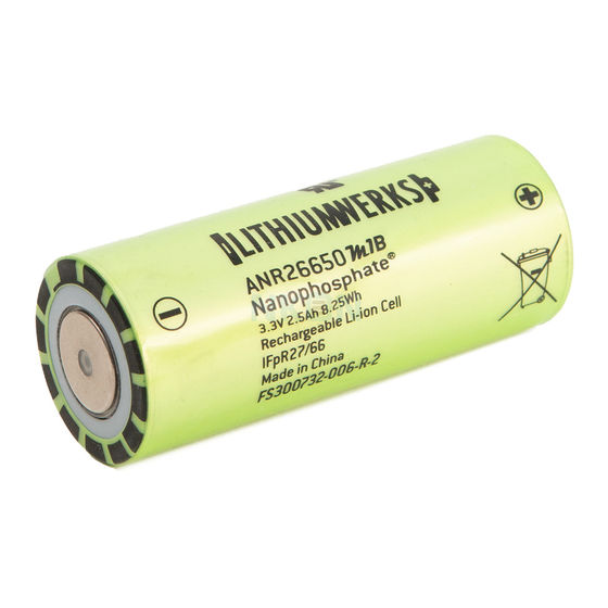
ANR26650M1-B General Specifications Refer to Table 20 for specifications for the ANR26650M1-B and Figure 32, on page 78, for a cell drawing. Note that actual performance of the cells may vary depending on use conditions and application. Table 20 – ANR26650M1-B cell specifications Specification Value Notes/Comments... - Page 79 ANR26650M1-B Maximum Current Limit Tables The max current tables in this section summarize the maximum recommended charge and discharge currents per cell for continuous and pulse operations with respect to SOC and cell temperature. Although the cells are capable of the listed currents and the actual limits for each application may be different depending on the battery pack environment, design, the cell’s age and the immediate and long-term operating history of the cells.
-
Page 80: Table 21 - Anr26650M1-B Max Continuous Charge Currents Wrt Temperature And Soc
ANR26650M1-B Table 21 – ANR26650 B Max continuous charge currents wrt temperature and SOC Table 22 – ANR26650 B Max 10s pulse charge currents wrt temperature and SOC Temp(°C) %SOC 100% Table 23 – ANR26650 B Max continuous discharge currents wrt temperature and SOC Temp(°C)... - Page 81 ANR26650M1-B Characterization Charts ANR26650 B Discharge Data at Various Rates ANR26650 B Discharge Data at Various Temperatures...
- Page 82 ANR26650 B Cycle Life at Various Temperatures ANR26650 B Calendar Life at Various Temperatures Estimated capacity fade for cells for 50% and 100 %...
- Page 83 ANR26650 B Open Circuit Voltage vs. State of Charge ANR26650 B Temperature Effects on OCV vs. SOC For examples of temperature effects on OCV vs. SOC, refer to the AMP20M1HD-A chart, on page 69. ANR26650 B DCR vs. SOC at Various Temperatures...
-
Page 84: Figure 32 - Anr26650M1-B Cell Diagram And Dimensions
ANR26650 B Capacity Degradation for Various Charge Rates For examples of capacity degradation for various charge rates, refer to the AMP20M1HD-A charts, on page 69. ANR26650M1-B Dimensions and Drawing Vent Score Figure 32 – ANR26650M1-B cell diagram and dimensions... -
Page 85: Apr18650M1-A
APR18650M1-A General Specifications Refer to Table 25 for specifications for the APR18650M1-A and Figure 33, on page 82, for a cell drawing. Note that actual performance of the cells may vary depending on use conditions and application. Table 25 – APR18650M1-A cell specifications... - Page 86 APR18650M1-A Maximum Current Limit Tables The max current tables in this section summarize the maximum recommended charge and discharge currents per cell for continuous and pulse operations with respect to SOC and cell temperature. Although the cells are capable of the listed currents and the actual limits for each application may be different depending on the battery pack environment, design, the cell’s age and the immediate and long-term operating history of the cells.
-
Page 87: Table 26 - Apr18650M1-A Max Continuous Charge Currents Wrt Temperature And Soc
APR18650M1-A Table 26 – APR18650 -A Max continuous charge currents wrt temperature and SOC Temp(°C) %SOC 100% 0.05 0.05 0.05 0.05 0.05 0.05 0.05 0.05 0.05 0.05 Table 27 – APR18650 -A Max 10s pulse charge currents wrt temperature and SOC Temp(°C)... -
Page 88: Figure 33 - Apr18650M1-A Cell Diagram And Dimensions
APR18650M1-A Dimensions and Drawing Figure 33 – APR18650M1-A cell diagram and dimensions... -
Page 89: Ahr32113M1Ultra-B
AHR32113M1Ultra-B General Specifications Refer to Table 30 for specifications for the AHR32113M1Ultra-B and Figure 34, on page 89 for a cell drawing. Note that actual performance of the cells may vary depending on use conditions and application. Table 30 – AHR32113M1Ultra-B cell specifications Specification Value Notes/Comments... - Page 90 AHR32113M1Ultra-B Maximum Current Limit Tables The max current tables in this section summarize the maximum recommended charge and discharge currents per cell for continuous and pulse operations with respect to SOC and cell temperature. Although the cells are capable of the listed currents and the actual limits for each application may be different depending on the battery pack environment, design, the cell’s age and the immediate and long-term operating history of the cells.
-
Page 91: Table 31 - Ahr32113M1Ultra-B Max Continuous Charge Currents Wrt Temperature And Soc
AHR32113M1Ultra-B Table 31 – AHR32113M1Ultra-B Max continuous charge currents wrt temperature and SOC Temp(°C) %SOC 100% 85 °C 65 °C 30 °C 25 °C 15 °C 10 °C 0 °C -10 °C -20 °C -30 °C -40 °C Table 32 – AHR32113M1Ultra-B Max 10s pulse charge currents wrt temperature and SOC Temp(°C)... - Page 92 AHR32113M1Ultra-B Characterization Charts AHR32113M1Ultra-B Discharge Data at Various Rates AHR32113M1Ultra-B Discharge Data at Various Temperatures...
- Page 93 AHR32113M1Ultra-B Cycle Life at Various Temperatures AHR32113M1Ultra-B Calendar Life at Various Temperatures Estimated capacity fade for AHR32113 for 50% SOC storage...
- Page 94 AHR32113M1Ultra-B Open Circuit Voltage vs. State of Charge AHR32113 Gen 2 cell: Open circuit voltage as a function of depth of discharge at 23 °C AHR32113M1Ultra-B Temperature Effects on OCV vs. SOC For examples of temperature effects on OCV vs.SOC, refer to the AMP20M1HD-A chart, on page 69. AHR32113M1Ultra-B DCR vs.
-
Page 95: Figure 34 - Ahr32113M1Ultra-B Cell Diagram And Dimensions
AHR32113M1Ultra-B Capacity Degradation for Various Charge Rates For examples of capacity degradation for various charge rates, refer to the AMP20M1HD-A charts, on page 69. AHR32113M1Ultra-B Dimensions and Drawing Figure 34 – AHR32113M1Ultra-B cell diagram and dimensions... -
Page 96: Acronyms And Terminology
Appendix B Acronyms and Terminology This appendix describes the terminology used in this document. Table 35 – Acronyms and terminology descriptions Acronym/Term Meaning Alternating Current Resistance. Usually refers to the resistance of a cell for very short pulses of current (< 1 second) Amp-Hour is a unit of measure of charge that can be stored or delivered to/from a battery. - Page 97 Acronym/Term Meaning Direct Current Resistance – Usually refers to the internal resistance of the cell for a defined pulse of current and time period. For example, at 10 amps at 10 seconds, the DCR of a cell is ____ ohms. Design Verification Testing Equivalent Lithium Content Energy Storage System...
Need help?
Do you have a question about the APR18650M1-A and is the answer not in the manual?
Questions and answers