
Summary of Contents for Sam4s SPT-3700 series
- Page 1 HOME LIST HELP PRINT Rev. 1.00.1211.E POS System Electronic Manuals SPT - 3700 series This manual consists of system introduction, system expansion and appendix A/B...
- Page 2 SPT-3700 (CTRL)+(Q) to end both. System Expansion System Introduction This manual provides technical information about the circuits, components and construction of the SAM4S POS System SPT-3700. The contents of this mamnual may be changed without prior notice. Intro Appendix A Safety Notices Before Images and contents of this manual may not be copied without permission.
- Page 3 HOME LIST HELP PRINT Electronic Manuals SPT-3700 series PDF electronic manual consists of system introduction, system Installation, system utilizing, system expansion, appendix A(BIOS set up), appendix B(System configuration) LI S T e-Manual e-Manual e-Manual e-Manual e-Manual e-Manual SPT-3700 SPT-3700 SPT-3700 SPT-3700 SPT-3700 SPT-3700...
- Page 4 SPT-3700 01. Intro System Introduction This manual provides technical information about the circuits, components and construction of the SAM4S POS System SPT-3700. The contents of this mamnual may be changed without prior notice. Intro Safety Notices Before Images and contents of this manual may not be copied without permission.
- Page 5 HOME LIST HELP PRINT PART 1. System Introduction e-Manual SPT-3700 01. Intro Warning messages and symbols System Introduction Warning messages are expressed by several symbols in this manuals. Warning messages are imperative sentences as below. Intro Safety Notices Before Installation or Use This symbol means there may be a risk of serious injury if not used properly.
- Page 6 HOME LIST HELP PRINT PART 1. System Introduction e-Manual SPT-3700 02. Safety Notices Before Installation or Use Read these cautions to avoid damage or injury. System Introduction Intro Cautions! Safety Notices Before Installation or Use Contents Keep rated voltage. System features Use the cleaner which is only for computer.
- Page 7 HOME LIST HELP PRINT PART 1. System Introduction e-Manual SPT-3700 03. Contents System Introduction Intro Safety Notices Before Installation or Use Contents System features Specification(Options) Name and Function of Each Component System Installation <Keyboard(option)> System Utilization <Mouse/Mouse pad(option)> System Expansion Appendix A BIOS Set up Appendix B...
- Page 8 HOME LIST HELP PRINT PART 1. System Introduction e-Manual SPT-3700 04. System Features System Introduction System Introduction Intro This product has passed rigorous quality testing. Safety Notices Before Installation or Use This product has a sophisticated design to arrange power and peripheral cables neatly and safely in any environment. Contents The all-in-one design incorporates the touch screen, credit card reader, smart card reader and various customer displays for clean and simple installations.
- Page 9 HOME LIST HELP PRINT PART 1. System Introduction e-Manual SPT-3700 05. System Specification(Options) System Introduction General Specifications Intel Atom Cedarview D2550 1.86GHZ Without FAN Processor Intro Intel NM10 Chip sets Safety Notices Before Installation or Use Intel Embedded Graphics Graphic Contents Data storage device SATA-ll (3.0Gb/s) 2.5 HDD / SSD / Cfast...
- Page 10 HOME LIST HELP PRINT PART 1. System Introduction e-Manual SPT-3700 05. System Specification(Options) Optional Specifications System Introduction Read Track: ISO track 1,2,3 Intro Interface: Internal USB Safety Notices Before Installation or Use Performance: 10~150CM/Sec Magnetic Swipe Reader(MSR) Contents Head Reliability: 500,000 times System features Error rate: Less than 0.5% Specification(Options)
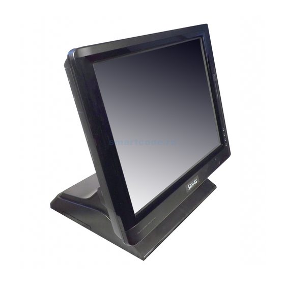
- Page 11 HOME LIST HELP PRINT PART 1. System Introduction e-Manual SPT-3700 06. Name and Function of Each Component System Introduction Front View Intro Safety Notices Before Installation or Use Contents Touch LCD System features Specification(Options) Name and MSR(Magnetic Stripe Reader) Function of Each Component The device for recognizing credit cards System Installation System Utilization...
- Page 12 HOME LIST HELP PRINT PART 1. System Introduction e-Manual SPT-3700 06. Name and Function of Each Component System Introduction Side View Intro Safety Notices Before Installation or Use Contents System features USB Connector Specification(Options) USB Devices can be used through this port, i.e. USB scanner, USB Keyboard, USB Printer, etc.
-
Page 13: Table Of Contents
HOME LIST HELP PRINT PART 1. System Introduction e-Manual SPT-3700 06. Name and Function of Each Component System Introduction I / O Intro Safety Notices Before Installation or Use Contents System features Specification(Options) Name and Function of Each Component System Installation System Utilization 1. -
Page 14: Part 1. System Introduction
HOME LIST HELP PRINT PART 1. System Introduction e-Manual SPT-3700 06. Name and Function of Each Component System Introduction Rear View Intro 7Inch Display or CDP(option) Safety Notices Before It shows advertisements or calculation. Installation or Use Contents System features Specification(Options) Name and Function of Each Component... -
Page 15: System Installation
HOME LIST HELP PRINT PART 2. System Installation e-Manual SPT-3700 01. Remove The Cable Cover System Introduction Tilt its monitor back to see hooks fixing cable cover. System Installation Push these hooks to remove the cover in order to see IO ports necessary for connecting peripherals. Remove The Cable Cover Remove Cable Tidy Dummy Keyboard/Mouse Connection... - Page 16 HOME LIST HELP PRINT PART 2. System Installation e-Manual SPT-3700 02. Remove Cable Tidy Dummy System Introduction System Installation Remove The Cable Cover Remove Cable Tidy Dummy Keyboard/Mouse Connection Printer Connection * Remove the cable tidy dummy if necessary to route cables. Serial Ports Connection RJ-11 Cash Drawer Connection Remove dual monitor expansion cover for when a dual monitor is installed.
- Page 17 HOME LIST HELP PRINT PART 2. System Installation e-Manual SPT-3700 03. Connecting Keyboard & Mouse Connect USB type keyboard & mouse. System Introduction System Installation Remove The Cable Cover Remove Cable Tidy Dummy Keyboard/Mouse Connection Printer Connection Serial Ports Connection RJ-11 Cash Drawer Connection RJ-45 LAN Cable Connection <Mouse>...
- Page 18 06. Connecting RJ-11 Cash Drawer DC Power Connection System Utilization Use RJ-11 drawer port in system when Cash Drawer is needed. (Use SAM4S Cash Drawer). System Expansion Appendix A Note! Cash drawer has 12V/24V that you can choose by the switch.
- Page 19 HOME LIST HELP PRINT PART 2. System Installation e-Manual SPT-3700 07. Connecting RJ-45 LAN Cable Connect LAN cable to RJ-45 LAN port to use internet. System Introduction It supports 100Mbps/1Gbps. System Installation Remove The Cable Cover <LAN Herb> Remove Cable Tidy Dummy Keyboard/Mouse Connection Printer Connection Serial Ports Connection...
- Page 20 (Free Voltage system adapter is used. Both 100V and 220V can be used.) System Installation Remove The Cable Cover ▶ Adapter for this system should be only from SAM4S . Cautions! Remove Cable Tidy Dummy ▶ SAM4S cannot be responsible for the damage caused by Keyboard/Mouse Connection using other products except SAM4S.
-
Page 21: System Utilization
HOME LIST HELP PRINT PART 3. System Utilization e-Manual SPT-3700 01. Use of Touch Screen Recalibrate if it is not accurate on touch points. System Introduction Click the right button of mouse on elo icon of Windows tray icons. And select Align... tab on the menu. System Installation System Utilization Use of Touch Screen... - Page 22 HOME LIST HELP PRINT PART 3. System Utilization e-Manual SPT-3700 01. Use of Touch Screen Recalibrate if it is not accurate on touch points. System Introduction If the recalibration is finished, click the green check button and end the recalibration program. System Installation System Utilization Use of Touch Screen...
- Page 23 HOME LIST HELP PRINT PART 3. System Utilization e-Manual SPT-3700 02. POS Driver and Utility Intorduction POS Driver & Other utilities are in Util_Driver folder of C driver. System Introduction System Installation System Utilization Use of Touch Screen POS Driver and Utility Introduction Use of Dual Monitors Drivers...
- Page 24 HOME LIST HELP PRINT PART 3. System Utilization e-Manual SPT-3700 02. POS Driver and Utility Intorduction POS Driver & Other utilities are in C:/Util_Driver/Utility System Introduction System Installation System Utilization Use of Touch Screen POS Driver and Utility Introduction Use of Dual Monitors Drawer Drivers POS Utility System Expansion...
- Page 25 HOME LIST HELP PRINT PART 3. System Utilization e-Manual SPT-3700 02. POS Driver and Utility Intorduction OPOS or OLE Retail POS consists of an architecture for win32-based POS device access. System Introduction The current OPOS driver has been developed in accordance with OPOS Specification Version 1.10 and continues to support the OPOS version. System Installation Support OS : WEPOS, Win XP Pro, POSReady 2009, POSReady 7, Win 7 Pro, Win 7 Ult System Utilization...
- Page 26 HOME LIST HELP PRINT PART 3. System Utilization e-Manual SPT-3700 03. Use of Dual Monitors Additional monitor can be connected to the VGA connector. This contents is written based on Windows 7 OS. System Introduction The system supports dual monitors that is using two monitors for one system. Sub-monitor can be displayed a screen copied a main-monitor s System Installation Windows desktop or can be display a screen extended Windows desktop.
- Page 27 HOME LIST HELP PRINT PART 3. System Utilization e-Manual SPT-3700 03. Use of Dual Monitors Additional monitor can be connected to the VGA connector. This contents is written based on Windows 7 OS. System Introduction System Installation Click the right button of mouse on Windows desktop screen, and select Screen resolution from a popup menu. System Utilization Use of Touch Screen POS Driver and...
- Page 28 HOME LIST HELP PRINT PART 3. System Utilization e-Manual SPT-3700 03. Use of Dual Monitors Additional monitor can be connected to the VGA connector. This contents is written based on Windows 7 OS. System Introduction System Installation On Change the appearance of your display dialog, the Display option is set as 1|2 Multiple Monitors and Multiple displays System Utilization option is set as Duplicate these displays .
- Page 29 HOME LIST HELP PRINT PART 3. System Utilization e-Manual SPT-3700 03. Use of Dual Monitors Additional monitor can be connected to the VGA connector. This contents is written based on Windows 7 OS. System Introduction System Installation If you want to change to an extended screen, set Multiple displays option as Extend these displays on Change the appearance of your display dialog.
- Page 30 HOME LIST HELP PRINT PART 3. System Utilization e-Manual SPT-3700 03. Use of Dual Monitors Additional monitor can be connected to the VGA connector. This contents is written based on Windows 7 OS. System Introduction System Installation Set Display option as 1. Digital Flat Panel (1024x768 60 Hz) and click Apply button.
- Page 31 HOME LIST HELP PRINT PART 3. System Utilization e-Manual SPT-3700 03. Use of Dual Monitors Additional monitor can be connected to the VGA connector. This contents is written based on Windows 7 OS. System Introduction System Installation Select Keep changes button on Display Settings dialog to keep the current settings. System Utilization Use of Touch Screen POS Driver and...
- Page 32 HOME LIST HELP PRINT PART 3. System Utilization e-Manual SPT-3700 03. Use of Dual Monitors Additional monitor can be connected to the VGA connector. This contents is written based on Windows 7 OS. System Introduction System Installation If the configuration is finished, click OK button to close the Change the appearance of your displays dialog.
- Page 33 HOME LIST HELP PRINT PART 3. System Utilization e-Manual SPT-3700 03. Use of Dual Monitors Additional monitor can be connected to the VGA connector. This contents is written based on Windows 7 OS. System Introduction Note! ▶ How to check dual monitor’s settings System Installation If dual monitors doesn’t work properly, refer to the following procedure.
-
Page 34: System Expansion
HOME LIST HELP PRINT PART 4. System Expansion e-Manual SPT-3700 01. System Disassembly System Introduction Make sure the system & peripherals power are off. System Installation System Utilization Take off the connector cab from the bottom of system in case it is fixed with screws. System Expansion Remove two screws Remove two screws... - Page 35 HOME LIST HELP PRINT PART 4. System Expansion e-Manual SPT-3700 01. System Disassembly(CDP) System Introduction CDP should be rotated as the direction shown in the figure and press PUSH area with hands. System Installation System Utilization System Expansion System Disassembly System Reassemble Upgrading Memory Module HDD Replacement...
- Page 36 HOME LIST HELP PRINT PART 4. System Expansion e-Manual SPT-3700 01. System Disassembly(CDP) System Introduction Lay the system while preventing LCD panel from being damaged. System Installation System Utilization System Expansion System Disassembly System Reassemble Upgrading Memory Module HDD Replacement MSR Removal Internal Speaker Removal Touch MSR Board Removal...
- Page 37 HOME LIST ADVICE PRINT PART 4. System Expansion e-Manual SPT-3700 01. System Disassembly(CDP) System Introduction Stand can be removed as the figure shown. System Installation System Utilization System Expansion System Disassembly System Reassemble Upgrading Memory Module HDD Replacement MSR Removal Internal Speaker Removal As referring to the figure, unscrew and release lock lever, and then the system back panel should be taken apart by pushing up the cover.
- Page 38 HOME LIST HELP PRINT PART 4. System Expansion e-Manual SPT-3700 01. System Disassembly(7 LCD) System Introduction LCD panel to prevent damage. Place the system, refer to figure. System Installation System Utilization System Expansion System Disassembly System Reassemble Upgrading Memory Module HDD Replacement MSR Removal Internal Speaker Removal...
- Page 39 HOME LIST HELP PRINT PART 4. System Expansion e-Manual SPT-3700 01. System Disassembly(7 LCD) System Introduction Remove the stand. System Installation System Utilization System Expansion System Disassembly System Reassemble Upgrading Memory Module HDD Replacement Disconnect the RGB & DC cable. MSR Removal Remove the screw to release the locking lever.
- Page 40 HOME LIST HELP PRINT PART 4. System Expansion e-Manual SPT-3700 01. System Disassembly(7 LCD) System Introduction Remove two screws on the inside of the cover as shown in picture. System Installation System Utilization System Expansion System Disassembly System Reassemble Upgrading Memory Module HDD Replacement MSR Removal Rear cover part of the PUSH press with your fingers to separate 7 display.
- Page 41 HOME LIST HELP PRINT PART 4. System Expansion e-Manual SPT-3700 01. System Disassembly System Introduction System dummy back panel can be removed with the aid of figure. System Installation System Utilization ② System Expansion System Disassembly System Reassemble Upgrading Memory Module HDD Replacement MSR Removal Internal Speaker Removal...
- Page 42 HOME LIST HELP PRINT PART 4. System Expansion e-Manual SPT-3700 03. Upgrading Memory Module In case the user requires to increase the main memory(RAM) capacity. System Introduction SPT-3700 uses DDRIII SODIMM package memory The memory can be up to 4GB System Installation Once the memory is installed, BIOS automatically recognizes System Utilization...
- Page 43 HOME LIST HELP PRINT PART 4. System Expansion e-Manual SPT-3700 04. HDD Replacement Check the hard drive type before replacing. The 2.5 inch SATA interface is the only interface supported. System Introduction System Installation Save data, turn off the system and disconnect the main power and all cables. System Utilization Disconnect power &...
- Page 44 HOME LIST HELP PRINT PART 4. System Expansion e-Manual SPT-3700 04. HDD Replacement Check the hard drive type before replacing. The 2.5 inch SATA interface is the only interface supported. System Introduction System Installation Remove bracket from the hard disk drive as shown in the figure. System Utilization Remove screws from the hard disk drive as shown in the figure.
- Page 45 HOME LIST HELP PRINT PART 4. System Expansion e-Manual SPT-3700 05. MSR(Magnetic Stripe Reader) Removal System Introduction Remove system back cover (refer to System Disassembly). System Installation Disconnect MSR (Magnetic Stripe Reader) cable. System Utilization Remove 3 screws which hold MSR bracket. System Expansion Remove MSR bracket as the figure below.
- Page 46 HOME LIST HELP PRINT PART 4. System Expansion e-Manual SPT-3700 06. Internal Speaker Removal System Introduction Remove system back cover (refer to System Disassembly). System Installation Disconnect speaker cable. System Utilization Remove speaker while pressing the hook which holds the speaker. System Expansion System Disassembly System Reassemble...
- Page 47 HOME LIST HELP PRINT PART 4. System Expansion e-Manual SPT-3700 07. Touch MSR Board Removal System Introduction Remove system back cover (refer to System Disassembly). System Installation Remove inverter. Disconnect all cables to Touch MSR board. System Utilization Remove Touch MSR board after undoing screws (2EA) which connect to the display bracket. System Expansion System Disassembly DALLAS Cable...
- Page 48 HOME LIST HELP PRINT PART 4. System Expansion e-Manual SPT-3700 08. LED Board Removal System Introduction Remove system back cover (refer to System Disassembly). System Installation Disconnect cables which connect LED board. Remove LED board after undoing screws (2EA) which hold LED board. System Utilization System Expansion System Disassembly...
- Page 49 HOME LIST HELP PRINT PART 4. System Expansion e-Manual SPT-3700 09. LPT Board Removal System Introduction Remove system back cover (refer to System Disassembly) System Installation Remove LPT board after undoing screws (2EA) which hold LPT board. Remove LPT board ass'y System Utilization System Expansion LPT board ass'y...
- Page 50 HOME LIST HELP PRINT PART 4. System Expansion e-Manual SPT-3700 10. Joint Harness Removal System Introduction Remove system back cover (refer to System Disassembly) System Installation Remove HDD module (refer to Replacing Hard Disk Drive on page 4-10). Remove Joint harness. System Utilization System Expansion System Disassembly...
- Page 51 HOME LIST HELP PRINT PART 4. System Expansion e-Manual SPT-3700 11. I/O Extension Board Removal System Introduction Remove system back cover (refer to System Disassembly) Speaker Cable System Installation Disconnect cables for HDD and remove HDD module (refer to Replacing Hard Disk Drive on page 4-11). System Utilization Disconnect cables for speaker and remove USB board (refer to System Disassembly) System Expansion...
- Page 52 HOME LIST HELP PRINT PART 4. System Expansion e-Manual SPT-3700 12. Main Board Removal System Introduction Remove system back cover as referring to System remove (4-4 page). System Installation Remove HDD module and inverter board. Disconnect all cables to main board. System Utilization Remove main board after undoing screws to main board and pushing the direction of arrow.
- Page 53 HOME LIST HELP PRINT PART 4. System Expansion e-Manual SPT-3700 13. Touch Panel Removal ▶ The touch panel is easily damaged from dust or mishandling while disconnecting the LCD and touch panel. Caution! System Introduction Please use an authorized service center for touch panel removal and replacement. System Installation Remove system back cover (refer to System Disassembly on page 4-4).
- Page 54 HOME LIST HELP PRINT PART 4. System Expansion e-Manual SPT-3700 13. Touch Panel Removal System Introduction Remove LCD and touch panel. System Installation Hand System Utilization System Expansion Hand System Disassembly System Reassemble Upgrading Memory Module HDD Replacement MSR Removal Internal Speaker Removal Touch MSR Board Removal LED Board Removal...
- Page 55 HOME LIST HELP PRINT PART 4. System Expansion e-Manual SPT-3700 14. LCD Panel Removal Caution! ▶ The touch panel is easily damaged from dust or mishandling while disconnecting the LCD and touch panel. System Introduction Please use an authorized service center for touch panel removal and replacement. System Installation Remove system back cover (refer to System Disassembly on page 4-4).
- Page 56 HOME LIST HELP PRINT PART 4. System Expansion e-Manual SPT-3700 14. LCD Panel Removal Remove LCD and touch panel. System Introduction System Installation Hand System Utilization System Expansion Hand System Disassembly System Reassemble Upgrading Memory Module HDD Replacement MSR Removal System Expansion Internal Speaker Removal Touch MSR Board Removal...
- Page 57 HOME LIST HELP PRINT PART 4. System Expansion e-Manual SPT-3700 14. LCD Panel Removal System Introduction Remove LVDS and inverter cable. Spread the cable in order not to be twisted with others. Inverter cable System Installation System Utilization System Expansion System Disassembly System Reassemble Upgrading Memory Module...
-
Page 58: Appendix Abios Set Up
HOME LIST HELP PRINT Appendix A. BIOS Set up e-Manual SPT-3700 01. Understanding BIOS Set Up BIOS provides configuration and set-up information for driving the main board. BIOS values are saved in CMOS ROM on the main board. System Introduction BIOS (Basic Input and Output System) Set-Up is a menu-oriented software utility which enables a user to configure the system's environmental set-up, System Installation system hardware, power saving functions, etc. - Page 59 HOME LIST HELP PRINT Appendix A. BIOS Set up e-Manual SPT-3700 01. Understanding BIOS Set Up BIOS provides configuration and set-up information for driving the main board. BIOS values are saved in CMOS ROM on the main board. System Introduction Initial Setup Screen System Installation Initial BIOS Set-Up Sreen has the following menu options:...
- Page 60 HOME LIST HELP PRINT Appendix A. BIOS Set up e-Manual SPT-3700 01. Understanding BIOS Set Up BIOS provides configuration and set-up information for driving the main board. BIOS values are saved in CMOS ROM on the main board. System Introduction →←...
- Page 61 HOME LIST HELP PRINT Appendix A. BIOS Set up e-Manual SPT-3700 02. Main Menu Use this menu for basic system setup such as time, date, system information and etc. System Introduction System Installation System Utilization System Expansion Appendix A BIOS set up Understanding BIOS Set Up Main Menu Advanced Menu...
- Page 62 HOME LIST HELP PRINT Appendix A. BIOS Set up e-Manual SPT-3700 03. Advanced Menu Use this menu to set up for system performance. System Introduction System Installation System Utilization System Expansion Appendix A BIOS set up Understanding BIOS Set Up Main Menu Advanced Menu Chipset Menu(Host Bridge)
- Page 63 HOME LIST HELP PRINT Appendix A. BIOS Set up e-Manual SPT-3700 03. Advanced Menu Use this menu to set up for system performance. System Introduction System Installation System Utilization System Expansion Appendix A BIOS set up Understanding BIOS Set Up Main Menu Advanced Menu Chipset Menu(Host Bridge)
-
Page 64: Advanced Menu
HOME LIST HELP PRINT Appendix A. BIOS Set up e-Manual SPT-3700 03. Advanced Menu Use this menu to set up for system performance. System Introduction System Installation System Utilization System Expansion Appendix A BIOS set up Understanding BIOS Set Up Main Menu Advanced Menu Chipset Menu(Host Bridge) - Page 65 HOME LIST HELP PRINT Appendix A. BIOS Set up e-Manual SPT-3700 03. Advanced Menu Use this menu to set up for system performance. System Introduction System Installation System Utilization System Expansion Appendix A BIOS set up Understanding BIOS Set Up Main Menu Advanced Menu Chipset Menu(Host Bridge)
- Page 66 HOME LIST HELP PRINT Appendix A. BIOS Set up e-Manual SPT-3700 03. Advanced Menu Use this menu to set up for system performance. System Introduction System Installation System Utilization System Expansion Appendix A BIOS set up Understanding BIOS Set Up Main Menu Advanced Menu Chipset Menu(Host Bridge)
- Page 67 HOME LIST HELP PRINT Appendix A. BIOS Set up e-Manual SPT-3700 03. Advanced Menu Use this menu to set up for system performance. System Introduction System Installation System Utilization System Expansion Appendix A BIOS set up Understanding BIOS Set Up Main Menu Advanced Menu Chipset Menu(Host Bridge)
- Page 68 HOME LIST HELP PRINT Appendix A. BIOS Set up e-Manual SPT-3700 03. Advanced Menu Use this menu to set up for system performance. System Introduction System Installation System Utilization System Expansion Appendix A BIOS set up Understanding BIOS Set Up Main Menu Advanced Menu Chipset Menu(Host Bridge)
- Page 69 HOME LIST HELP PRINT Appendix A. BIOS Set up e-Manual SPT-3700 03. Advanced Menu Use this menu to set up for system performance. System Introduction System Installation System Utilization System Expansion Appendix A BIOS set up Understanding BIOS Set Up Main Menu Advanced Menu Chipset Menu(Host Bridge)
- Page 70 HOME LIST HELP PRINT Appendix A. BIOS Set up e-Manual SPT-3700 03. Advanced menu Use this menu to set up for system performance. System Introduction System Installation System Utilization System Expansion Appendix A BIOS set up Understanding BIOS Set Up Main Menu Advanced Menu Chipset Menu(Host Bridge)
- Page 71 HOME LIST HELP PRINT Appendix A. BIOS Set up e-Manual SPT-3700 03. Advanced menu Use this menu to set up for system performance. System Introduction System Installation System Utilization System Expansion Appendix A BIOS set up Understanding BIOS Set Up Main Menu Advanced Menu Chipset Menu(Host Bridge)
- Page 72 HOME LIST HELP PRINT Appendix A. BIOS Set up e-Manual SPT-3700 03. Advanced menu Use this menu to set up for system performance. System Introduction System Installation System Utilization System Expansion Appendix A BIOS set up Understanding BIOS Set Up Main Menu Advanced Menu Chipset Menu(Host Bridge)
- Page 73 HOME LIST HELP PRINT Appendix A. BIOS Set up e-Manual SPT-3700 04. Chipset Menu(Host Bridge) Chipset is the device supporting the data transfer/control between CPU and peripheral components. System Introduction System Installation System Utilization System Expansion Appendix A BIOS set up Understanding BIOS Set Up Main Menu Advanced Menu...
- Page 74 HOME LIST HELP PRINT Appendix A. BIOS Set up e-Manual SPT-3700 04. Chipset Menu(Host Bridge) Chipset is the device supporting the data transfer/control between CPU and peripheral components. System Introduction System Installation System Utilization System Expansion Appendix A BIOS set up Understanding BIOS Set Up Main Menu Advanced Menu...
- Page 75 HOME LIST HELP PRINT Appendix A. BIOS Set up e-Manual SPT-3700 04. Chipset Menu(Host Bridge) Chipset is the device supporting the data transfer/control between CPU and peripheral components. System Introduction System Installation System Utilization System Expansion Appendix A BIOS set up Understanding BIOS Set Up Main Menu Advanced Menu...
- Page 76 HOME LIST HELP PRINT Appendix A. BIOS Set up e-Manual SPT-3700 04. 05. Chipset Menu(South Bridge) South bridge - You can set the items for PCI bus system. It is responsible for PCI, IDE, USB devices. System Introduction System Installation System Utilization System Expansion Appendix A...
- Page 77 HOME LIST HELP PRINT Appendix A. BIOS Set up e-Manual SPT-3700 04. 05. Chipset Menu(South Bridge) South bridge - You can set the items for PCI bus system. It is responsible for PCI, IDE, USB devices. System Introduction System Installation System Utilization System Expansion Appendix A...
- Page 78 HOME LIST HELP PRINT Appendix A. BIOS Set up e-Manual SPT-3700 04. 05. Chipset Menu(South Bridge) South bridge - This section describes configuring the PCI bus system. PCI, IDE, USB devices are set in this section, System Introduction System Installation System Utilization System Expansion Appendix A...
- Page 79 HOME LIST HELP PRINT Appendix A. BIOS Set up e-Manual SPT-3700 05. Boot Menu System Introduction System Installation System Utilization System Expansion Appendix A BIOS set up Understanding BIOS Set Up Main Menu Advanced Menu Chipset Menu(Host Bridge) Chipset Menu(South Bridge) Boot Menu Security Menu Save &...
- Page 80 HOME LIST HELP PRINT Appendix A. BIOS Set up e-Manual SPT-3700 06. Security Menu This menu allows you to provide/revise supervisor and user password. System Introduction System Installation System Utilization System Expansion Appendix A BIOS set up Understanding BIOS Set Up Main Menu Advanced Menu Chipset Menu(Host Bridge)
- Page 81 HOME LIST HELP PRINT Appendix A. BIOS Set up e-Manual SPT-3700 07. Save & Exit Menu This menu allows you to load the optimal default settings, and save or discard the changes to the BIOS items. System Introduction System Installation System Utilization System Expansion Appendix A...
-
Page 82: Appendix B System Configuration
HOME LIST HELP PRINT Appendix B. System Configuration e-Manual SPT-3700 01. System Block Diagram System Block Diagram System Introduction EIC10-SAM(D2550) System Installation System Utilization System Expansion Appendix A BIOS Set up Appendix B System configuration System Block Diagram Main Board Configuration A Deal Drawing ◀... - Page 83 HOME LIST HELP PRINT Appendix B. System Configuration e-Manual SPT-3700 02. Main Board Configuration Main Chipset & Connector SATA1 F-PANEL System Introduction HDD POWER SATA2 USB 6 System Installation GPIO IN / OUT USB 7/8 System Utilization SERIAL (COM5 / 6) System Expansion Appendix A SO-DIMM...
- Page 84 HOME LIST HELP PRINT Appendix B. System Configuration e-Manual SPT-3700 02. Main Board Configuration Main Jumper Setting System Introduction System Installation BIOS Clear Jumper(JCMOS1) Jumper Setting Voltage System Utilization 1 - 2 Short Normal Operation(Default) 2 - 3 Short CMOS Clear System Expansion Serial(JPC5/6) Voltage Jumper Appendix A...
- Page 85 HOME LIST HELP PRINT Appendix B. System Configuration e-Manual SPT-3700 02. Main Board Configuration IO pin map System Introduction Serial communication port System Installation System Utilization System Expansion Appendix A BIOS Set up Appendix B System Configuration COM1/2/4(DSUB9 MALE) COM3/COM6(RJ45) System Block Diagram Main Board Configuration Assignment...
- Page 86 HOME LIST HELP PRINT Appendix B. System Configuration e-Manual SPT-3700 02. Main Board Configuration IO pin map System Introduction USB & LAN Ports System Installation System Utilization System Expansion Appendix A BIOS Set up Appendix B System Configuration System Block Diagram USB Port(TYPE A) LAN Port(RJ45) Main Board Configuration...
- Page 87 HOME LIST HELP PRINT Appendix B. System Configuration e-Manual SPT-3700 02. Main Board Configuration IO pin map System Introduction Printer port System Installation System Utilization Pin Num In/Out /STROBE /STROBE /WRITE System expansion Appendix A BIOS Set up Appendix B System Configuration System Block Diagram Main Board Configuration...
- Page 88 HOME LIST HELP PRINT Appendix B. System Configuration e-Manual SPT-3700 02. Main Board Configuration IO pin map System Introduction Cash Drawer Port / Cash Drawer Power Selection Switch System Installation System Utilization System Expansion Appendix A BIOS Set up Appendix B System Configuration System Block Diagram Main Board Configuration...
- Page 89 HOME LIST HELP PRINT Appendix B. System Configuration e-Manual SPT-3700 02. Main Board Configuration IO pin map System Introduction DC Power Jack System Installation System Utilization System Expansion Appendix A BIOS Set up Appendix B System Configuration Adapter Input +12V Adapter Output +12V System Block Diagram Main Board Configuration...
- Page 90 HOME LIST HELP PRINT Appendix B. System Configuration e-Manual SPT-3700 03. A Deal Drawing PART CODE PARTS NAME Q' TY Serviceable REMARK System Introduction ASS'Y-MAIN DISPLAY JK72-20283A PMO-COVER CABLE S600300020A SCREW-TAPTITE System Installation JK95-70330A MEA-LEVER HINGE JK91-10036A PHA-MAIN STAND System Utilization A4-1 JK72-20304A PMO-STAND A4-2 JK70-20101B IPR-HINGE SUPPORT(R) System Expansion...
- Page 91 HOME LIST HELP PRINT Appendix B. System Configuration e-Manual SPT-3700 03. A Deal Drawing NO PART CODE PARTS NAME Q' TY Serv iceable REMARK B1 JK72-20288 PMO-FRONT DISPLAY Buyer SPEC(Silk) System Introduction B2 S600200023A SCREW-TAPPING B3 JK72-20284A PMO-COVER DECO B4 JK72-20294A PMO-LENS LED System Installation B5 JK72-20602A...
- Page 92 HOME LIST HELP PRINT Appendix B. System Configuraton e-Manual SPT-3700 03. A Deal Drawing P AR T CODE P AR T S NAM E Q' T Y S e r vic e a ble R EM AR K C1 JK95-70328A MEA-BRKT DISPLAY(M) System Introduction C2 JK95-70335C...
- Page 93 HOME LIST HELP PRINT Appendix B. System Configuration e-Manual SPT-3700 03. A Deal Drawing P AR T CODE P AR T S NAM E Q' T Y S e r vic e a ble R EM AR K QCD-V202 OPTION-CDP(CHARACTER) OPTION System Introduction QCD-G256...
Need help?
Do you have a question about the SPT-3700 series and is the answer not in the manual?
Questions and answers