
Summary of Contents for Fabet F330
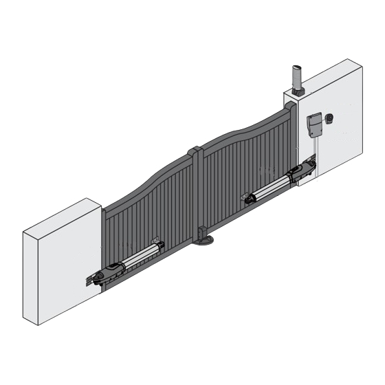
- Page 1 F330 SWING GATE OPENERS 24V DC GEAR MOTOR FOR RESIDENTIAL USER MANUAL Flashing Light Push Button Control box Gate 2 Gate 1 400-820-3735 www.fabetgroup.com...
-
Page 3: Table Of Contents
The Gear Motors (Dip 6.Slow) Description of The Automation 4.2.3 Operation Speed Adjustment of Description of Devices The Gear Motors (Dip 7.Fast) 2.3.1 F330 Electromechanical 4.2.4 Single and Dual Gate Operation Gear Motors Adjustment (Dip 8.Ds/Set) 2.3.2 PC200 Control Box LED Indication 2.3.3... - Page 4 If there is a failure that cannot be solved and is not mentioned in this manual, please contact qualified Keep all the components of F330 system and this manual installation personnel. for further consultation. Do not use the gate-automated system before all the...
-
Page 5: Description Of The Automation
2.1 Applications F330 is applied for residential automation of single or dual leaf gate. F330 has to be operated with electricity and it’s forbidden to be operated by back-up batteries for normal use. Back-up batteries are only allowed for emergent operation when there is a power failure, and the gear motors can be released by special keys to move the gate manually. -
Page 6: Control Box
2.3.1 F330 Electromechanical Gear Motors Figure 3 F330 consists of a worm screw reduction gear and a 24V direct current motor. The gear motor could be released manually by special release keys when there is 1)F330 a power failure. The gear motor is installed with two post brackets, one rear plate and one front plate for the installation. -
Page 7: Installation 5
3.1 Notes of Motors in Operation The F330 gate openers are applicable to per leaf of 4.0 meters in width and 350 kg in weight which can be opened up to 120 degrees primarily for residential use; where the performance shall be influenced by the factors such as gate dimension, weight and climate that the driven torque is necessarily to be adjusted properly. - Page 8 3.2 Power Connection F330 comes with two power cables of 2m and 7m long, which requires very low voltage that no professionally trained personnel is required in installation; however, the users are advised to read the installation manual carefully before going for it.
- Page 9 3.3 Installation 3.3.1 Preparation for Motor Installation F330 is not applicable to a gate which is inefficient or unsafe, neither to solve the defects due to incorrect installation nor poor maintenance. Check the following items before going for installation: 1). Make sure the weight and dimensions of the gate conform to the operation range of F330. Don’t use F330 if the gate specifications do not meet the requirements.
- Page 10 100 degrees, then the value of “B” is approximate 190mm. **Please make sure “B” and “A” are similar or the same in value that the leaves can be operated smoothly, also to reduce the burden of the motor. INSTRUCTIONS F330...
- Page 11 9. Please make sure the front plate is completely installed horizontally. Figure 22 Figure 21 10. Refer to Figure 23, the distance between front plate of the motor and rear plate is 798mm (F330), the difference in height is 2.5mm (F330). Figure 23...
- Page 12 1) Turn the round plate on the release part to “OPEN” position. See Figure 29. 2) Push out the release part to the end. See Figure 30. 3) Use the release key to turn the pin anti-clockwise to the end. See Figure 31. Figure 29 Figure 30 Figure 31 INSTRUCTIONS F330...
- Page 13 8). Turn the key and insert the shell on the bottom. Turn the key back to the center position and the shell will be fixed to the bottom. 9). Tighten the lock body with the two screws and insert the round cover by pressing it to attach to the whole unit. Figure 3.3.3 (5) Figure 3.3.3 (6) INSTRUCTIONS F330...
- Page 14 3.) Connect the wires and penetrate the wires into the hole of the base. See Figure 3.3.5 (3). 4.) Drill the holes in the wall and fix the bottom to the wall by three screws. See Figure 3.3.5 (4). Figure 3.3.5 (1) Figure 3.3.5 (2) Figure 3.3.5 (3) Figure 3.3.5 (4) INSTRUCTIONS F330...
-
Page 15: Ph-1 Photocells
Figure 3.3.6 (4) NA: Normal Open C: Common NA NC NA NC NC: Normal Close CA: AC(12~24) : DC(+) Input Voltage CC: DC(12~24) : DC(-) Input Voltage VERT:Vertical ORIZ:Horizontal Vertical Adjustment Power LED: Green Horizontal Adjustment LED:Red(Beam Alignment) INSTRUCTIONS F330... -
Page 16: Pel-1 Electric Latch And Ps-1 Stopper
See Figure 3.3.7 (4), Figure 3.3.7 (5), Figure 3.3.7 (6) & Figure 3.3.7 (7) Figure3.3.7(6) Figure3.3.7(4) Unscrew the screws. Figure3.3.7(5) Take the casing off. The location of the spring. (Installation) Figure3.3.7(7) Change the spring and screw it in the different place. INSTRUCTIONS F330... - Page 17 3). The gap between the bottom of electric latch and the stopper should be less than 7mm. See Figure 3.3.7 (10) Figure3.3.7(10) For the gate opened inward. Figure3.3.7(11) For the gate opened Outward. 4). Connect the wires of the electric latch to the terminal LAT(+) and LAT(-) on the PCB. INSTRUCTIONS F330...
-
Page 18: Pc200 Control Box
2). PEL-1 Electric Latch: Connect the two wires from the electric latch to the terminal LAT (+) and LAT (-) on the PCB. 3). F330 Gear Motors: Refer to Figure 3.3.8(5) and connect the wires separately to the terminals on the PCB. - Page 19 Figure 3.3.8(5) Transformer INSTRUCTIONS F330...
-
Page 20: Dip Switch Setting
4.1.2 Over-current Adjustment (Dip 2.Over2 & Dip 3.Over1) OVER1 OVER2 Current (Amp) Dip Switch 3 OFF Dip Switch 2 OFF Dip Switch 3 ON Dip Switch 2 OFF Dip Switch 3 OFF Dip Switch 2 ON Dip Switch 3 ON Dip Switch 2 ON INSTRUCTIONS F330... -
Page 21: Gate Auto-Close Adjustment (Dip 4.Auto
OFF: The speed is 80% output of the full speed. 4.2.4 Single and Dual Gate Operation Adjustment (Dip 8.Ds/Set) ON: Dual Gates operation in system learning and normal operation. OFF: Single Gate operation in system learning and normal operation. INSTRUCTIONS F330... -
Page 22: Led Indication
5 seconds. The transmitter learning is completed when the blue indicator is “OFF”. (B) Transmitter Memory Erasing: Press and hold the S3 button on the PCB for three seconds. (C) One radio receiver can be memorized with 200pcs of transmitters. INSTRUCTIONS F330... -
Page 23: Gate Operation
ASk: Transmitter button A for single leaf operation. DkB: Transmitter button B for double leaves operation. PR-1 Situation 2: See the following description: BSk: Transmitter button B for single leaf operation. DkA: Transmitter button A for double leaves operation. INSTRUCTIONS F330... -
Page 24: Trouble Shooting
AC and battery terminals. The gear motors does not run and the relay is Check if the fuse is burned. noisy when operating the gate opening and closing INSTRUCTIONS F330... -
Page 25: Technical Characteristics
Operating Temperature -20 ~+50 Dimension 844mm * 115mm * 106mm Weight 6.25kg 6.2 PC200 Control Box Application For F330 power supply Main power supply 230Vac/110Vac, 50Hz/60Hz Back-up battery 2pcs of batteries for emergency operation, 1.2A each Transformer 6A, 24V Receiver board 433.92MHz;... -
Page 26: Pf-1 Flashing Light
3V with one CR2032 button type lithium battery Operating Temperature -20 ~+50 Dimension 71.5mm * 33mm * 14mm 6.8 PEL-1 Electric Latch Application For locking the gate. Power Supply 24Vdc Operating Temperature -20 ~+50 Operating Current Dimension 61mm * 55mm * 120mm INSTRUCTIONS F330... -
Page 27: Declaration Of Conformity
Manufacturer: Timotion Technology Co., Ltd. Address: Shiyong Minying Industrial Zone, Hengli Town, DongGuan City, GuangDong, China Model: F330; PC200; PR-1 1. Certificate of conformity of a product with the essential requirements art. 3.2 of the R&TTE Directive 1999/5/EC. 2. The above product has been tested with the listed standards and in compliance with the European Directive LVD 2006/95/EC.
Need help?
Do you have a question about the F330 and is the answer not in the manual?
Questions and answers